19
ATtiny22/22L
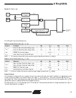
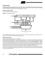
Figure 22. Reset Logic
The ATtiny22/L has a fixed startup time.
Notes:
1. The Power-On Reset will not work unless the supply voltage has been below V
POT
(falling).
Notes:
1. The Power-On Reset will not work unless the supply voltage has been below V
POT
(falling).
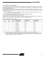
Power-On Reset
The ATtiny22/L is designed for use in systems where it can operate from the internal RC oscillator or in applications where
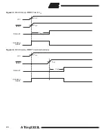
a clock signal is provided by an external clock source. After V
CC
has reached V
POT
, the device will start after the time t
TOUT
(see Figure 23). If the clock signal is provided by an external clock source, the clock must not be applied until V
CC
has
reached the minimum voltage defined for the applied frequency.
The start-up time t
TOUT
is one watchdog cycle. The frequency of the watchdog oscillator is voltage dependent as shown in
“Typical characteristics” on page 44.
Table 3. Reset Characteristics (V
CC
= 5.0V)
Symbol
Parameter
Min
Typ
Max
Units
V
POT
Power-On Reset Threshold Voltage, rising
1.0
1.4
1.8
V
Power-On Reset Threshold Voltage, falling
0.4
0.6
0.8
V
V
RST
RESET Pin Threshold Voltage
0.6 V
CC
V
t
TOUT
Reset Delay Time-Out Period ATtiny22/L
11
16
21
µs
Table 4. Reset Characteristics (V
CC
= 3.0V)
Symbol
Parameter
Min
Typ
Max
Units
V
POT
Power-On Reset Threshold Voltage, rising
1.0
1.4
1.8
V
Power-On Reset Threshold Voltage, falling
0.4
0.6
0.8
V
V
RST
RESET Pin Threshold Voltage
0.6 V
CC
V
t
TOUT
Reset Delay Time-Out Period ATtiny22/L
22
32
42
µs
Power-On Reset
Circuit
Reset Circuit
Watchdog
Timer
On-Chip
RC-Oscillator
14-Stage Ripple Counter
Q0
Q13
Q3
Q
Q
S
R
INTERNAL
RESET
POR
VCC
RESET
100 - 500K
COUNTER RESET

