


5-2
Demonstration Kit User Guide
5183A–ZIGB–12/07/06
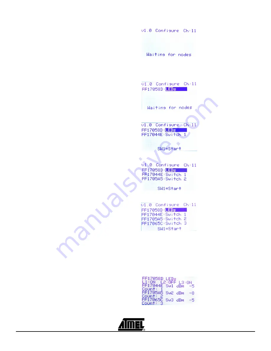
Figure 5-3.
Channel selected and waiting for nodes.
The four remaining RCBs can now be powered on in random order. Figure 5-4 through
Figure 5-7 shows the Configure screen as the nodes are powered on.
Figure 5-4.
First device found, assign as LED
Figure 5-5.
Second device found, and assigned as Switch 1 (Toggles LED1)
Figure 5-6.
Third device found, and assigned as Switch 2 (Toggles LED2)
Figure 5-7.
Fourth device found, and assigned as Switch 3 (Toggles LED3)
The Configure screen is used to reconfigure the network nodes. After the nodes have
been configured in this screen,
SW1
toggles the display between the Configure screen
and the Network Monitor screen shown in Figure 5-8.
Figure 5-8.
Network monitor screen
Summary of Contents for AT86RF230
Page 1: ...ATAVRRZ200DemonstrationKit AT86RF230 2450 MHz band Radio Transceiver User Guide ...
Page 2: ......
Page 4: ...ii Demonstration Kit User Guide 5183A ZIGB 12 07 06 ...
Page 11: ...Demonstration Kit User Guide 3 3 5183A ZIGB 12 07 06 Figure 3 4 Display Board connectors ...
Page 12: ...3 2 Demonstration Kit User Guide 5183A ZIGB 12 07 06 ...
Page 22: ...6 2 Demonstration Kit User Guide 5183A ZIGB 12 07 06 ...
Page 24: ...7 2 Demonstration Kit User Guide 5183A ZIGB 12 07 06 ...


