background image

AT-OPUS-810M, AT-OPUS-68M, & AT-OPUS-46M

31

webGUI

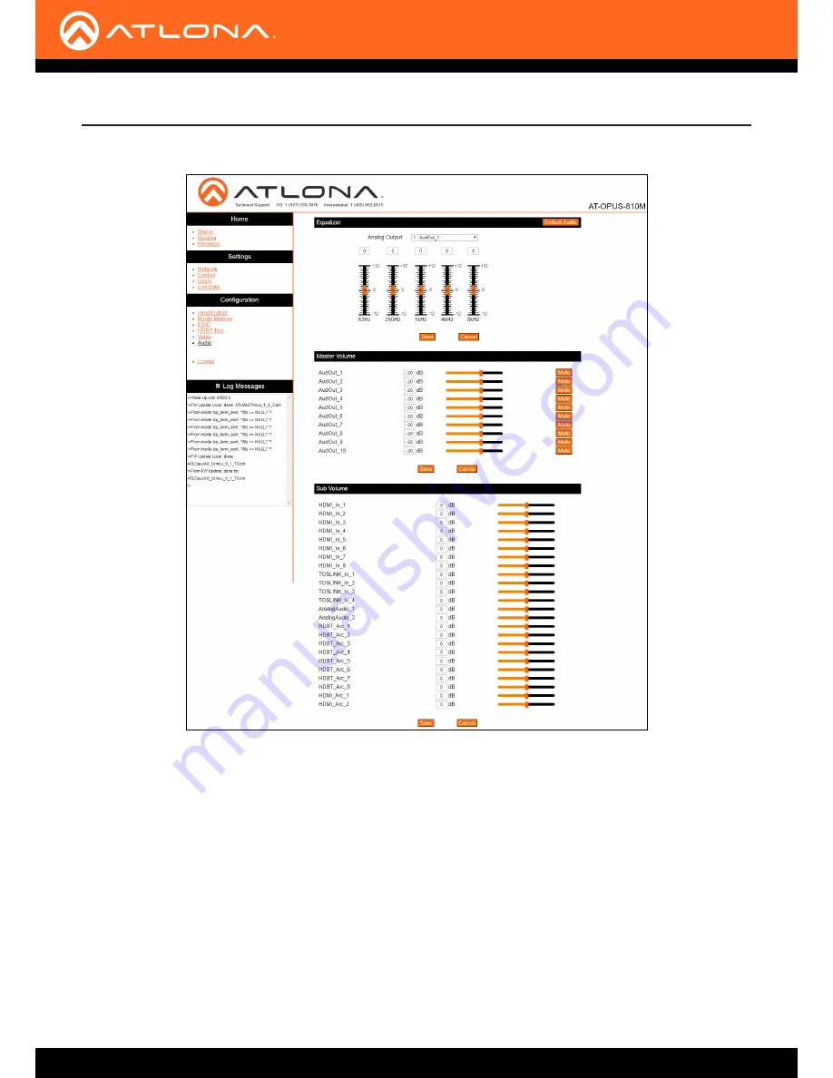
17  Select 

Audio

 from the side menu.

Equalizer

Default Audio

 - Resets all the audio settings to factory default. Analog audio will be equalized to 0 on all 5 

bands, master audio will be set back to -20 dB, and the Sub Volumes will all be set back to 0 dB.

Analog Output

 - Select the analog audio output to adjust the 5 band equalization on. Save each adjustment 

before switching to another output.

Slider and adjustment field

 - Use the slider to adjust between level -12 and 12 on each band, or type the desired 

numeric value into the field above the slider.

Master Volume

Adjust the analog audio output volume value individually by slider or manual input from -71 dB to 15 dB or 

completely mute the audio using the Mute button found next to the slider. This will adjust the analog audio 

output only. 

Sub Volume

Adjust the volume level of the input signals using manual input into the dB fields or by adjusting the slider to 

the desired level.

Summary of Contents for Opus AT-OPUS-810M

Page 1: ...AtlonaManuals 4KHDR MatrixSwitcherSeries AT OPUS 810M AT OPUS 68M AT OPUS 46M HDMI to HDBaseT OpusTM 4K HDR Matrix Switcher...

Page 2: ...AT OPUS 810M AT OPUS 68M AT OPUS 46M 2 Version Release Date Notes 1 10 18 Initial release 2 11 18 Added Front Panel Operation Version Information...

Page 3: ...gister will not affect the product warranty To register your product go to http www atlona com registration Sales Marketing and Customer Support Welcome to Atlona Main Office Atlona Incorporated 70 Da...

Page 4: ...Limited Product Warranty Terms New Products 10 years from proof of purchase date for hardware electronics products purchased on or after June 1 2013 3 years from proof of purchase date for hardware e...

Page 5: ...ies districts or states do not allow the exclusion or limitation of relief special incidental consequential or indirect damages or the limitation of liability to specified amounts so the above limitat...

Page 6: ...Do not use this product near water Keep away from wet places such as spas pools sinks laundries wet basements etc 4 When cleaning unplug the unit and wipe with a dry cloth Do not use damp cloths clea...

Page 7: ...endation Guidelines 10 Installation 11 Control 11 Mounting Instructions 12 Connection Instructions 14 Connection Diagram 14 Front Panel Operation 15 Routing 15 Basic 15 ALL 15 Info 16 IP 16 Static 16...

Page 8: ...9 x Captive screw connector 4 pin 12 x Captive screw connector 3 pin 1 x Pair rack mount ears 4 x Feet w screws 1 x IEC power cord 1 x IR remote control 1 x Installation Guide Introduction Features Pa...

Page 9: ...x through either IR or RS 232 10 TOSLINK OUT These ports provide digital audio output to audio DSPs amplifiers or player devices 11 AUDIO IN Connect unbalanced 2CH audio sources to these ports 12 IR I...

Page 10: ...e bars Cable Recommendation Guidelines Core Shielding CAT5e CAT6 CAT6a CAT7 Solid UTP unshielded N A STP shielded Performance Rating MHz 350 500 600 800 Use of a TIA EIA 568B termination is recommende...

Page 11: ...connector for control has been included The first three terminals are RS 232 control the last two terminals are for IR IR IN is connected by a ground and signal wire Use with 3rd party control system...

Page 12: ...INK PoE LINK PoE LINK AT OP US 810 M HDMI IN AT OP US 810 M CANCE L INFO EDID FNC 1 2 3 4 POWE R ENTER 6 7 8 9 5 10 OPUS TM NOTE Increase the air flow as needed to maintain the recommended temperature...

Page 13: ...he desired location A T O P U S 8 1 0 M C A N C E L IN FO E D ID FN C 1 2 3 4 P O W E R E N T E R 6 7 8 9 5 1 0 O P U S TM 1 2 3 4 5 6 7 8 1 2 3 4 5 6 7 8 9 10 A U D IO IN 1 2 1 2 3 4 5 6 7 8 9 10 LA...

Page 14: ...2 3 4 5 6 7 8 1 2 3 4 5 6 7 8 9 10 AUD IOIN 1 2 1 2 3 4 5 6 7 8 9 10 LAN DEB UG IRIN RS 2 32 RX S TX R L R L AUD IOOUT R L R L R L R L R L R L R L R L R L R L 1 2 TOS LINK IN 3 4 1 2 3 4 5 6 7 8 9 10...

Page 15: ...for each function For basic A V routing the front panel can be used Basic ALL To route a single input to all the outputs use the ALL function 1 Select the button that corresponds with the desired inp...

Page 16: ...y basic information for the unit firmware version IP address IP port and MAC address By default the unit will come with DHCP enabled If a DHCP server is not detected it will set itself to a static IP...

Page 17: ...an output EDID 4 Select the key that corresponds with the output to save the EDID from 5 Press the ENTER button to confirm the selection When successful a EDID saved message will appear and the unit w...

Page 18: ...DIDs to the input to ensure compatibility with that display Press 2 for Saved followed by the memory number the EDID was saved to and then ENTER to complete the EDID load c Select an internal EDID to...

Page 19: ...be turned on and off to ensure no stray IR signals from blasters are received 1 Select the FNC button 2 Press the 2 button to pull up the IR menu 3 Select the 2 button to turn off the IR front panel w...

Page 20: ...isplayed 4 Enter the following information on the Login page Login admin Password Atlona 5 Click the Login button The info page will display giving all the general information of the AT OPUS NOTE If t...

Page 21: ...utputs Firmware UI HDMI FW and FPGA Firmware The current matrix firmwares will display in these fields Verify the latest firmware by checking the individual product pages under the Firmware tabs https...

Page 22: ...to control the unit via TCP IP 8 Select Network from the side menu HDBaseT Receivers Link status A red circle will display when no receiver is connected or it is receiving no signal A green circle wi...

Page 23: ...R 5 and 6 on AT OPUS 46M 9 Select Control from the Side menu webGUI System Power Toggles the unit between on and standby IR Turns the IR window on the front of the unit on and off Key Lock Lock and un...

Page 24: ...GUI Users Additional Users Add up to three additional users each with individual passwords Admin Password Update the admin password for the matrix Only the admin password may be changed the username w...

Page 25: ...ct Log Data from the side menu webGUI Log Data These sections will allow selections as to which specific items the unit will log from FW update warnings to video switching The in depth logs will allow...

Page 26: ...t 1 to output 1 input 2 to output 2 etc and audio ports to the corresponding HDMI input port Ports 9 and 10 will follow ports 1 and 2 respectively 46M ports 5 and 6 will follow port 1 and 2 68M ports...

Page 27: ...wn menu Ports with active source signals will appear black Audio Output Select the desired audio source from the drop down menu Corresponding analog audio and TOSLINK audio ports will use the same sou...

Page 28: ...Selection Use the drop down menu to select from default highest common resolution between source and display 16 internal EDIDs and the previously saved EDIDs Internal EDID Internal EDID 1 ATL 1080P 2C...

Page 29: ...1500 2000 and 3000 milliseconds HDBT Zone Use the drop down menu to select which HDBaseT output is being tested Only active connections can be tested Start Stop Use the start stop button to run or can...

Page 30: ...30 webGUI 16 Select Video from the side menu Video Output Control Output Port Future Feature Input HDCP Status Displays the current HDCP status of the output The HDCP status states are No Connection...

Page 31: ...h adjustment before switching to another output Slider and adjustment field Use the slider to adjust between level 12 and 12 on each band or type the desired numeric value into the field above the sli...

Page 32: ...810M 46M 1 through 4 for input and 1 through 6 for output 68M 1 through 6 for input and 1 through 8 for output To route the HDMI inputs and outputs 1 Make sure the unit is powered on if not select the...

Page 33: ...0 1200 1680 1050 1600 1200 1600 900 1440 900 1400 1050 1366 768 1360 768 1280 1024 1280 800 1280 768 1152 768 1024 768 800 600 Color Space YUV RGB Chroma Subsampling 4 4 4 4 2 2 4 2 0 Color Depth 8 bi...

Page 34: ...meters H x W x D 3 47 x 17 24 x 11 79 88 1 x 438 x 299 5 H x W x D w feet 3 89 x 17 24 x 11 79 98 8 x 438 x 299 5 Rack Size 2U Weight Pounds Kilograms Device 11 91 lbs 5 4 kg Certification Unit CE FCC...

Page 35: ...registered trademarks of Atlona Inc All other brand names and trademarks or registered trademarks are the property of their respective owners Pricing specifications and availability subject to change...

Reviews: