4
Installation Guide
AT-OME-ST31A
1. Connect HDMI cables from HD/UHD sources to
INPUT 2
and
INPUT 3
.
2. Connect a USB-C cable from a source to
INPUT 1
on the switcher.
3. Connect an Ethernet cable, from the
HDBaseT
port to a compatible HDBaseT receiver.
4. Connect an HDMI cable from the
HDMI
output port to a display or other sink device.
5. Connect an Ethernet cable from the
LAN
port to the Local Area Network.
6. OPTIONAL: Connect an audio output device to the AUDIO OUT port, using the included
captive screw connector block. Refer to
Audio Output Connector (page 3)
information.
7. OPTIONAL: Connect an RS-232 cable from the control device to the
RS-232
port on the
AT-OME-ST31A. Refer to
for wiring information.
Installation
NOTE:
The AT-OME-ST31A is powered over HDBaseT, by a PoE receiver unit.
If a PoE HDBaseT receiver is not used, then the AT-OME-ST31A must be
powered using the external 24 V DC power supply* (not included). When used
with the external power supply, the AT-OME-ST31A can provide power to the
connected USB-C device. This power supply can be purchased from Atlona.
* Optional power supply is available from Atlona. Part no. AT-PS-245-D4.
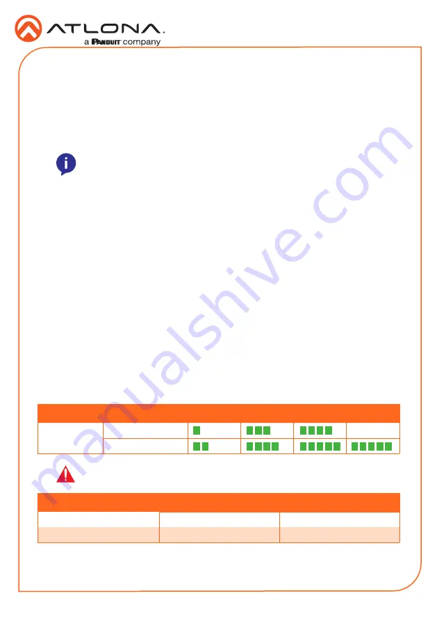
Refer to the tables below for recommended cabling when using Altona products with HDBaseT.
The green bars indicate the signal quality when using each type of cable. Higher-quality signals
are represented by more bars.
Cable Recommendation Guidelines
Core
Shielding
CAT5e
CAT6
CAT6a
CAT7
Solid
UTP (unshielded)
N/A
STP (shielded)
*Atlona recommends TIA/EIA 568-B termination for optimal performance.
Cable*
Max. Distance @ 4K
Max. Distance @ 1080p
CAT5e
295 feet (90 meters)
330 feet (100 meters)
CAT6 / CAT6a / CAT7
330 feet (100 meters)
330 feet (100 meters)
IMPORTANT:
Stranded or patch cables are not recommended due to
performance issues.


