background image

www.atlona.com | toll free: 

1-877-536-3976

For International: 1-

408-962-0515

6

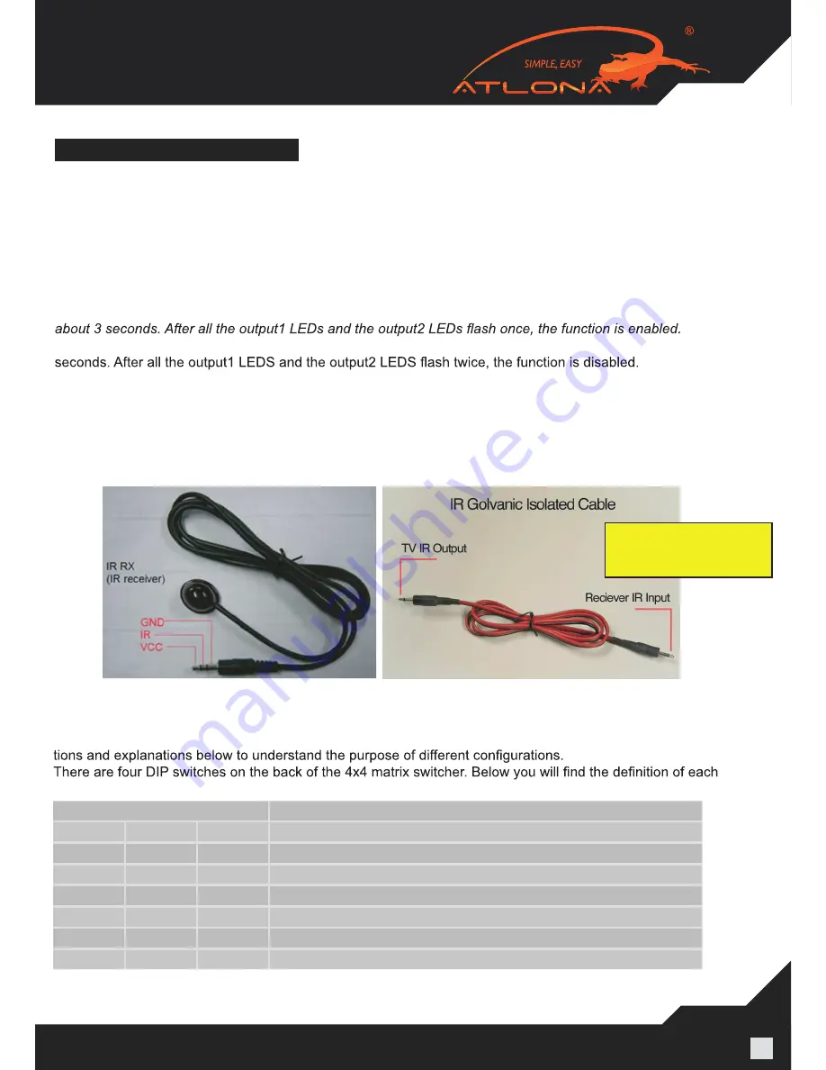
Note: For better functionality of the IR, we suggest to place the IR receiver Eye at the IR Eye of the controlling source. 

8)  EDID Settings (PLEASE READ, IT IS VERY IMPORTANT): 

The functionality of the switch will depend on how you select the DIP Switches below. Please read the instruc-


one of the dip switches.

Position ID

EDID Operational Mode

1

2

3

OFF

OFF

OFF

AUTO EDID MANAGEMENT (DIP # 1)

OFF

OFF

ON

Record EDID (DIP # 2)

OFF

ON

OFF

Up to 1080P with Stereo Audio (DIP#3)

ON

OFF

OFF

Up to 1080P with 5.1 Audio (DIP#4)

ON

OFF

ON

Up to 1080P with 7.1 Audio (DIP#5)

OFF

ON

ON

Up to 1080i with Stereo Audio (DIP#6)

Note: 1 – ON and 0 – OFF

CONNECT AND OPERATION

1) Connect the HDMI input sources (such as HD-DVD, PS3, AppleTV, DirecTV etc) into the inputs on AT-PRO-

HD0408M-SR. 

2) Connect the HDMI outputs from AT-PROHD0408M-SR (such as LCD, Plasma, LED, Projector, Monitor) 

3) Power on the input source you want to show. (Keep the unused input power off, otherwise it may interfere 

with the normal display.) 

4) Use IR remote, front panel, RS232, TCP/IP or RS485 connections to choose desired input source.  

5) IR calls back from remote locations allows controlling the matrix switch as well as nearby sources (such as 

DVD, AppleTV, Satellite, Cable and etc…). 

Note: To enable the function: press the output2 selection button and the key lock button at the same time for 

*Disable the function: press the output2 selection button and the key lock button at the same time for about 3 


7)  Instruction on IR Emitter. 

The sequence of “IR1, IR2, IR3, IR4” one-to-one correspond with “HDMI INPUTS1 through 4”. When an output 

chooses certain input, the call-back IR signal of RJ45 on this output will choose the corresponding “IR” port to 

send the signal out. 
For example, OUTPUT1 chooses INPUT3, then the call-back IR signal of RJ45 on OUTPUT1 will choose “IR 

3” to send the signal out.

When connecting Galvanic Isolated

Cable, connect the Stereo Side to

the HDMI Receiver and Mono to

the TV IR Output

Summary of Contents for AT-PROHD44M-SR

Page 1: ...www atlona com toll free 1 877 536 3976 For International 1 408 962 0515 AT PROHD44M R AT PROHD44M S User Manual AtlonA 4x4 HDMI matrix Switch with 4 x CAT5 Receivers included AT PROHD44M SR...

Page 2: ...e Contents 3 3 Features 3 4 Specification 4 5 Panel Description 4 5 1 Main Unit 4 5 1 1 Front Panel 4 5 1 2 Rear Panel 5 5 2 HDMI Receiver 5 6 Connect and Operation 6 7 IR Remote Control 8 7 1 RS232 C...

Page 3: ...4 x AT PROHD REC CAT5 6 7 receivers 4 x 5 VDC Power Supply 110 240v universal for receivers 1 x 12V DC Power Supply 110 240v universal for the main switch 1 x IR Remote 1x IR receiver extension cable...

Page 4: ...TIONS Operating Temperature Range 5 to 35 C 41 to 95 F Operating Humidity Range 5 to 90 RH no condensation Input Video Signal 0 5 1 0 volts p p Input DDC Signal 12v main unit and 5v receivers Video Fo...

Page 5: ...ote The TCP IP port has to be connected to the computer via direct Crosswire CAT5 6 7 wire while if connected to the router it needs to be connected though Straight wire 1 2 3 4 5 6 7 8 9 HDMI Receive...

Page 6: ...ojector Monitor 3 Power on the input source you want to show Keep the unused input power off otherwise it may interfere with the normal display 4 Use IR remote front panel RS232 TCP IP or RS485 connec...

Page 7: ...ewbuilt inEDIDmodes thismodeisforresolutionsupto1080Pwith5 1DigitalAudio This mode is designed for applications where user has AV Receivers in each remote location which are able to accept Digital Aud...

Page 8: ...for AT PROHD44M SR There are 2 scenarios which codes to use User will need to learn all 64 x codes in order to control each location when pointing at the switcher User will only need to learn 8 x cod...

Page 9: ...elect Input 3 cir 0D Output 1 select Input 4 cir 63 Output 2 select Input previous cir 62 Output 2 select Input next Output 2 cir 19 Output 2 select Input1 cir 1B Output 2 select Input2 cir 11 Output...

Page 10: ...ly with the receiver b Also we suggest checking the termination of the wire with RJ45 tested all 8 wires have to work c HDMI receiver is not plugged in to the power outlet d Try another input on the T...

Page 11: ...matically turn off If this occurs unplug the device and plug it back in Protect and route power cords so they will not be stepped on or pinched by anything placed on or against them Be especially care...

Page 12: ...ed for the remainder of the original warranty period or 3 year whichever is longer 3 NO OTHER WARRANTIES TO THE MAXIMUM EXTENT PERMITTED BY APPLICABLE LAW ATLONA TECHNOLOGIES AND ITS SUPPLIERS DISCLAI...

Page 13: ...tration creates an ownership record if your product is lost or stolen and helps ensure you ll receive notification of performance issues and firmware updates At Atlona we respect and protect your priv...

Reviews: