


6
Installation Guide
AT-HDR-EX-70-2PS
When performing an HDBaseT test, connecting to either the transmitter or receiver will
provide the same results.
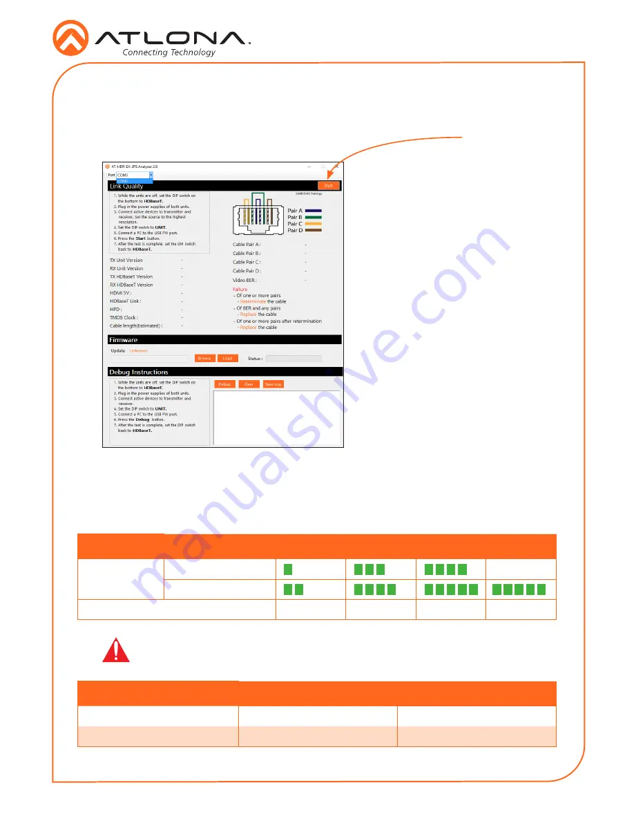
7. Launch the AT-HDR-EX-70-2PS Analyzer software.
8. Click the
Start
button.
•
If the HDBaseT link integrity is
good, then all tests will display as
“Pass”.
•
If any part of the HDBaseT cable
fails, then a numerical value, in
decibels, will be displayed next
to the associated pair, under the
Signal Quality
section.
These values can be reported
to Atlona Technical Support
Engineers to help resolve possible
issues.
Start button
9. After testing is complete, set the
DIP switch on the bottom of the
unit to the
HDBaseT
position.
Refer to the tables below for recommended cabling when using Altona products with HDBaseT.
The green bars indicate the signal quality when using each type of cable. Higher-quality signals
are represented by more bars.
*Atlona recommends TIA/EIA 568-B termination for optimal performance.
Cable Recommendation Guidelines
Core
Shielding
CAT5e
CAT6
CAT6a
CAT7
Solid
UTP (unshielded)
N/A
STP (sheilded)
Recommended Bandwidth (MHz)
350
500
600
800
Cable*
Max. Distance @ 4K
Max. Distance @ 1080p
CAT5e / CAT6
115 feet (35 meters)
200 feet (60 meters)
CAT6a / CAT7
130 feet (40 meters)
230 feet (70 meters)
IMPORTANT:
Stranded or patch cables are not recommended due to
performance issues.


