background image

AT-GAIN-120

22

Basic Operation

Network Audio

The AT-GAIN-120 supports Dante and AES67 audio streams with the addition of the optional AT-GAIN-NET audio 

card, which can be purchased from Atlona.  Refer to 

Network Audio Card Installation (page 38)

 for information on 

card installation.

For setup and control of Dante / AES67 audio routing and configuration, refer to the Audinate Dante Controller 

software.  AMS 2.0 and the web graphical interface of the AT-GAIN-120 supports basic network, control, and audio 

level adjustments.

1. 

Download the Audinate Dante Controller software from the following URL:


https://www.audinate.com/products/software/dante-controller 


2. 

Make sure that an Ethernet cable is connected from the 

INPUT

 port on the rear panel to the network.

3. 

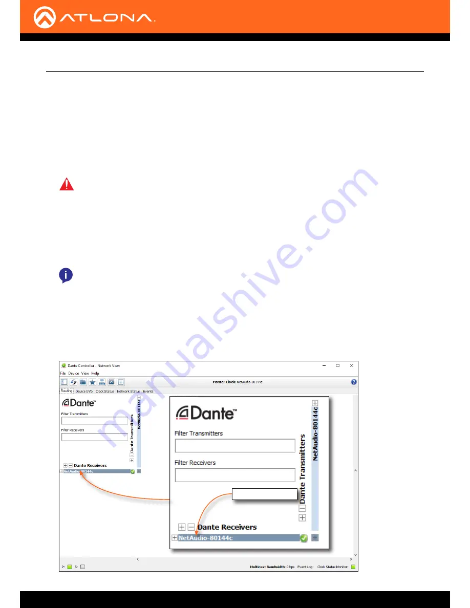
Launch the Dante Controller software.


The AT-GAIN-NET network audio card will appear as 

NetAudio-xxxxx

, where 

xxxxx

 refers to the last five 

hexadecimal digits of the network card MAC address.

Dante Software 

Configuration

IMPORTANT:

  The AT-GAIN-120 must be connected within the same network segment as the Dante 

Controller, in order to utilize mDNS.

NOTE:

 The AT-GAIN-120 was tested using Audinate Dante Controller software v4.0.6.5 and Java 

v1.8.0.  Atlona recommends using Audinate Dante Controller software v4.0.6.5 or higher.

AT-GAIN-NET card

Summary of Contents for AT-GAIN-120

Page 1: ...AtlonaManuals Audio AT GAIN 120 Audio Power Amplifier Stereo Mono 120 Watts...

Page 2: ...AT GAIN 120 2 Version Release Date Notes 1 4 18 Initial release Version Information...

Page 3: ...oluntary and failure to register will not affect the product warranty To register your product go to http www atlona com registration Sales Marketing and Customer Support Welcome to Atlona Operating N...

Page 4: ...uct Warranty Terms New Products 10 years from proof of purchase date for hardware electronics products purchased on or after June 1 2013 3 years from proof of purchase date for hardware electronics pr...

Page 5: ...s or states do not allow the exclusion or limitation of relief special incidental consequential or indirect damages or the limitation of liability to specified amounts so the above limitations or excl...

Page 6: ...ole de la fl che du triangle quilat ral est destin alerter l utilisateur de la pr sence d une tension dangereuse non isol e dans l enceinte du produit qui peut tre suffisamment importante pour constit...

Page 7: ...Do not use this product near water 6 Clean only with a dry cloth 7 Do not block any ventilation openings Install in accordance with the manufacturer s instructions 8 Do not install or place this prod...

Page 8: ...icators 19 Power Modes 20 Powering On or Off 20 Auto Power Down mode 20 Hibernation mode 21 Network Audio 22 Dante Software Configuration 22 Enabling AES67 Support 23 Volume Control 25 Factory Reset 2...

Page 9: ...face AT GAIN NET receives two channel audio from OmniStream AV encoders or compatible audio devices Optional AT RACK 1RU rack shelf highly recommended for rack installation Automatic standby after 25...

Page 10: ...more information 6 ANALOG IN Connect an audio source to this port using the included 5 pin captive screw connector Refer to Audio Connectors page 11 for wiring information 7 RESET Press and hold this...

Page 11: ...port When connecting program stereo speakers set the MODE switch to either 4 or 8 depending upon the speakers impedance Audio Connectors ANALOG IN LINE OUT 4 8 OUT GND Side View Side View GND 2 1 3 2...

Page 12: ...Remove at least 3 16 5 mm from the insulation of each wire 3 Connect the wires as shown Voltage level Function Voltage is 0 or less than 3 V Off Voltage is 3 V or greater 30 V max On Connect a distri...

Page 13: ...8 This mode is used for consumer applications and shorter speaker cable runs Connection Instructions Installation Program stereo speakers low impedance Distributed speakers high impedance 4 Connect th...

Page 14: ...yer AT GAIN 120 Distributed Speakers Audio Ge ne ric SPEA KER SYST EMS SPEA KER SYST EMS Ge ne ric SPEA KER SYST EMS SPEA KER SYST EMS Ge ne ric SPEA KER SYST EMS SPEA KER SYST EMS Ge ne ric SPEA KER...

Page 15: ...then the unit will be assigned the following IP configuration IP address 192 168 1 254 Subnet mask 255 255 0 0 Gateway 192 168 1 1 If a static IP address is desired the unit can be switched to static...

Page 16: ...requires three arguments the desired IP address of the AT GAIN 120 the subnet mask and the gateway address All arguments must be entered in dot decimal notation The following is an example IPStatic 1...

Page 17: ...sired web browser and enter the IP address of the AT GAIN 120 2 Log in using the required credentials The factory default username and password are listed below Username admin Password Atlona 3 Click...

Page 18: ...AT GAIN 120 18 Basic Operation 5 The following message box will be displayed 6 Click OK to accept the changes or click Cancel to abort changes and return to the Network page...

Page 19: ...s live Firmware update is in progress Refer to Updating the Firmware page 34 for more information SIGNAL Solid green An active signal is present on the selected input DEVICE ID Off Flashing green Unit...

Page 20: ...ired web browser and enter the IP address of the AT GAIN 120 2 Log in using the required credentials The factory default username and password are listed below Username admin Password Atlona 3 Click t...

Page 21: ...ing methods Press and hold the IP RESET button on the rear panel for approximately 3 seconds but no longer that 5 sec onds using the end of a paper clip or other pointed object Pull the trigger high u...

Page 22: ...e Controller software from the following URL https www audinate com products software dante controller 2 Make sure that an Ethernet cable is connected from the INPUT port on the rear panel to the netw...

Page 23: ...NET audio card has a maximum of two channels of audio Refer to the Dante Controller User Guide for details on operation 1 Double click the network card under Dante Receivers Enabling AES67 Support In...

Page 24: ...the New drop down list and select Enabled 4 A message box will be displayed prompting to confirm AES67 is to be enabled Click Yes 5 Another message box will be displayed In order for AES67 to be enabl...

Page 25: ...22 2 4 20 19 14 9 22 2 4 20 19 14 9 dB ANALOG IN L 4 8 OUT 70V 100V OUT AT GAIN 120 PWR 100 120VAC 60Hz 120W 220 240VAC 50Hz 120W L R L R IP 4 8 100V 70V R INPUT GAIN L R RESET button Output audio le...

Page 26: ...efer to IP Configuration page 15 The default static IP address of the AT GAIN 120 is 192 168 1 254 Introduction to the Web GUI 1 Launch a web browser 2 In the address bar type the IP address of the AT...

Page 27: ...ged out the AT GAIN 120 will display the login screen Menu Bar The window on the left side of the screen is the menu bar The menu system is divided into three sections Home Settings and Configuration...

Page 28: ...ick this button to save the system settings to a local file System settings files are saved in bin binary format The default system settings filename is systemsettings bin It is recommended to save th...

Page 29: ...rmware update procedure Browse Click this button to select the firmware file Click the Load button to begin the update procedure Refer to Updating the Firmware page 34 for more information Load Click...

Page 30: ...80 This field cannot be modified IP Timeout Enter the time out interval in seconds in this field This field represents the time interval before the TCP IP connection times out Hostname Enter the desi...

Page 31: ...own mode Refer to Auto Power Down mode page 20 for more information Hibernation Enables or disables hibernation mode Refer to Hibernation mode page 21 for more information Unit Trigger Enables or disa...

Page 32: ...eld Special characters e g etc are not permitted Save Cancel Click the Save button to apply all changes Click the Cancel button to abort changes Change Admin Password Old password Enter the current pa...

Page 33: ...all equalizer bands to their default settings Refer to Default Settings page 41 for more information Mute Click this button to mute the audio output Note that clicking this button will mute all audio...

Page 34: ...nected between the AT GAIN 120 and the network The computer used to access the web GUI must be on the same network as the AT GAIN 120 2 Type the IP address of the AT GAIN 120 into the web browser as s...

Page 35: ...d uses the default name of systemsettings bin 7 Click Firmware on the left side of the screen 8 Click the Browse button to select the firmware file 9 Click the Load button to begin the upgrade process...

Page 36: ...and drop the firmware file on the computer to this folder Wait for the file to be copied 7 Disconnect both the USB cable and power cable from the AT GAIN 120 8 Reconnect the power to the AT GAIN 120 T...

Page 37: ...VO L LEVE L AU DIO AM PLIFIER FW SIG NA L AN AL OG IN NE T AU DIO DE VIC E ID GA INTM LA N IN PU T NE TW OR K AU DI O RE SE T RE SE T LIN E OU T CL AS S 2 W IRI NG CL AS S 2 W IRI NG TR IG GE R MO DE...

Page 38: ...place After the faceplate is removed set it aside Keep the two screws to attach the included faceplate with the INPUT card WARNING To prevent the risk of electrocution or electric shock always discon...

Page 39: ...uide and gently push the AT GAIN NET network card forward until it locks in place The card will make a small snapping sound once the card is in place Lower Rail Upper Rail Plastic Guides IMPORTANT Whe...

Page 40: ...ghten the screws using high torque devices as this may cause damage to the screws or the faceplate assembly 7 Card installation is complete 8 Connect the power cable to the AT GAIN 120 9 Connect an Et...

Page 41: ...e digits of serial number OFF Control Power Auto Power Down Auto Power Down Timer min Hibernation Unit Trigger Blink OFF Enabled 15 Disabled Disabled Disabled Users Admin username Admin password admin...

Page 42: ...ator green DEVICE ID 1 LED indicator green ANALOG IN 1 LED indicator green NET AUDIO 1 LED indicator green VOL LEVEL 1 Multi LED indicator Input Signal Analog Input Balanced 20 k unblanced 10 k CMRR 5...

Page 43: ...to 70 C Humidity RH 90 RH non condensing Power Standby Mode Powers down after 5 25 minutes adjustable of no signal complies with ENERGY STAR power consumption limits of 0 5 W in standby mode Consumpti...

Page 44: ...34 updating using USB 36 H Hibernation mode See Power modes hibernation mode I Installation 11 IP configuration using commands 16 using rear panel 15 using the web GUI 17 L LED indicators 19 M Mode s...

Page 45: ...AT GAIN 120 45 Index V Volume adjusting 25 33 W Warranty 4 Web GUI 26...

Page 46: ...registered trademarks of Atlona Inc All other brand names and trademarks or registered trademarks are the property of their respective owners Pricing specifications and availability subject to change...

Reviews: