


D 20
unit and must be used when starting the installed unit.
Like Forced Draft burners, all Pre-Mix burners must be
tested and adjusted, as necessary, to the factory set-
tings.
•
Prior to Start-Up, check to make sure all the installation
procedures have been followed as outlined in this man-
ual. This includes compliance with all local and state
codes as well as the manufacturer’s requirements.
D.3. F
ACTORY
T
EST
R
EPORT
(FTR)
Every Triton Series™ boiler is supplied with a Factory Test
Report (FTR). The FTR details the actual factory test set-
tings for this unit as tested prior to shipment.
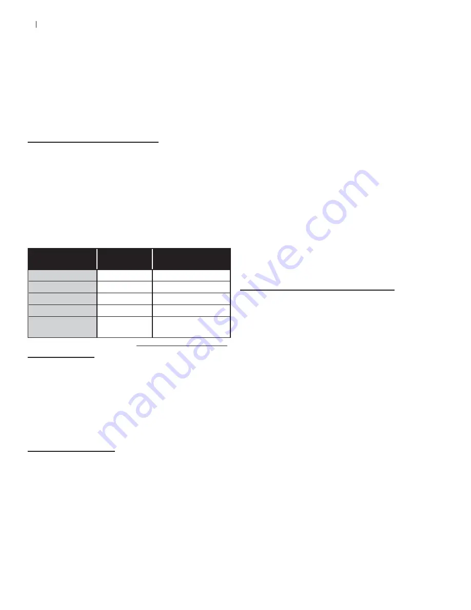
•
When the boiler is started up, it is important to check
the following parameters and adjust them to the values
seen on the factory test report. Please record the
values in the blank spaces below. The values must be
within the ranges shown below.
I. Condition
II. Value
III. Acceptable
Range
Carbon Monoxide:
ppm Less Than 100 ppm
Carbon Dioxide:
% Between 7- 9%
Excess Air:
% 30-45%
NOx:
ppm Less Than 20 ppm
Comb. Chamber
Pressure:
WC Under 0.5” WC
Table D.3.1. Start Up Parameters
D.4. V
ERIFICATION
1. Check the boiler nameplate and verify the voltage, type
of gas, gas pressure and regulator setting.
2. Verify that a wind de ecting vent cap is securely fas-
tened to the vent outlet to prevent downdrafts.
3. Read and verify the ame safeguard system installed
on the unit. All Triton Series™ units have a prepurge
and a postpurge time cycle of 7 seconds.
D.5. S
TART
-U
P
D
ETAIL
1. Verify and record the gas valve model, venturi model,
blower model, venting inlet and outlet sizes, and air
lter size.
2. Verify, but do not record the supply gas pressure, the
electrical voltage, the vent stack and the free combus-
tion air openings to the boiler room to ensure that they
meet the requirements on the nameplate, local codes,
gas industry standards and the O & M manual.
•
Upon start-up, the ame safeguard will initialize and be-
gin a prepurge cycle. Blower relay energizes and turns
on the Combustion Blower and the Auxiliary Blower.
•
Combustion Air Flow Switch closes and the Combus-
tion Blower drives to prepurge speed.
•
Prepurge rate is veri ed with blower feedback signal
and initiates 7 second prepurge.
•
After prepurge is completed, the combustion blower
drives to light off rate.
•
After light off rate is veri ed, 10 second PFEP (Pilot
Flame Establishment Period) is initiated.
•
During the rst half of PFEP, the Pilot Valve Solenoid
and Spark Transformer are both energized.
•
Spark Transformer is de-energized during second half
of PFEP and only Pilot Valve is energized.
•
When pilot ame is prooven, 4 second MFEP (Main
Flame Establishment Period) is initiated.
•
During MFEP, the Main Safety Shutoff Valve and Pilot
Valve Solenoids are energized and ring rate is held at
light off rate.
•
After MFEP, the Pilot Valve is de energized and the
Main Burner modulates its ring rate according to load
demand.
3. If a steady ame is not established, check the ame
failure signals on the ame safeguard and correct the
condition causing the ame failure. Several tries for
ignition may be required to purge the air from the gas
line.
D.6. S
TART
U
P
A
ND
M
AINTENANCE
T
ESTS
D.6.a. Gas Supply Piping Leak Test
Upon rst installing the Triton Series™ boiler, it is important
to check the gas supply line for leaks.
1. Follow the National Fuel Gas Code for instructions on
proper gas line piping and gas leak tests.
2. Measuring gas pressures can help detect leaks in iso-
lated lines. Temporarily install a manometer or pressure
gauge with an upper limit of no more than 5 times the
testing pressure, 5 x 14” WC = 2.6psi for Triton Se-
ries™ boiler installations between the manual gas shut
off on the boiler and supply line’s regulator.
3. Leaving the shut off valve closed on the boiler, open
the supply line momentarily until the installed manom-
eter reads a stable pressure and record the pressure
and ambient temperature.
4. Close the supply line and monitor the gas pressure for
a drop in pressure. The test should be monitored for at
least 10 minutes or ½ hour per each 500 ft
3
of volume
in the testing pipe.
5. At the end of the monitoring period, record the gas
pressure and temperature. If there is a drop in pres-
sure, a gas leak may be present and should be further
investigated (Note: signi cant temperature variations
may cause changes in the gas pressure and should be
retested).
Summary of Contents for Triton T-80
Page 31: ...E 29 E 3 ELECTICAL WIRING DIAGRAM ...
Page 43: ...F 41 ...
Page 44: ...F 42 ...
Page 45: ...F 43 ...
Page 46: ...F 44 Notes ...


