Owner’s Manual
HPA-DAC4
Dante
®
Accessory Card
AtlasIED.com
– 7 –
Specifications are subject to change without notice.
1601 Jack McKay Blvd. • Ennis, Texas 75119 U.S.A.
Telephone: 800.876.3333 • Fax: 800.765.3435
Connecting the HPA-DAC4 to a Dante
®
Network
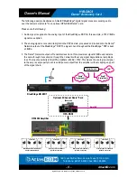
Refer to the example below on how to connect a simple Dante
®
network audio system. There are
three items needed to make a Dante
®
network, (1) gigabit router, Dante
®
transmitter and a Dante
®
receiver. In the illustration example below the AtlasIED BlueBridge
®
BB-168DT is the transmitter
and the HPA-DAC4 is the receiver. The HPA-DAC4 installed into the HPA amplifier becomes the HPA
amplifier’s Inputs 1-4. The router and the CAT5e cable connect the devices together.
Figure 5 is a configuration snapshot of the GUI of the BB-168DT. Analog inputs 1-4 are routed to a
limiter, then onto the network outputs 1-4. Where signal goes from the BB-168DT network output is
determined by a separate software called Dante
®
Controller. Dante
®
Controller is free software that
allows connectivity and signal routing within Dante
®
devices.
Figure 6 shows the BB-88DT and HPA-DAC4 on the Dante
®
Network. The HPA amplifier model number
will not appear in the Dante
®
Controller GUI because the amplifier is not the recognized Dante
®
device, the HPA-DAC4 is. The accessory card installed in the amplifier combines the digital and
analog platforms. The cells that have been connected are indicated by the green highlighted circle
with the check mark. These highlighted cells indicate the routing of the BB-88DT transmitters
01, 02, 03, 04 (BB-88DT network output 1, 2, 3, 4) to the HPA-DAC4 (Atlas4-0a004b) receiver channels
1, 2, 3, 4 (HPA amplifier inputs 5-8).
Figure 5
Note:
Always
add a limiter
before the
network output.
Set the limiter
threshold to
0dBu to prevent
clipping the
input of the HPA
amplifier.
Figure 6
Green check circles
indicate a specific
channel connection
between the Dante
®
transmitting device
and the Dante
®
receiving device.
Note:
Can be
renamed in Dante
®
Controller


