- 40 -
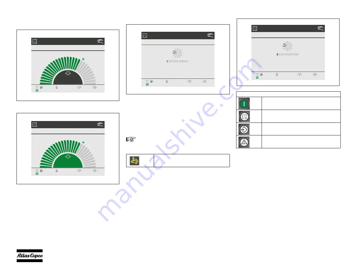
Set the Pressure/Flow Setpoint
When the controller is in the Main View (shift between
PRESSURE and FLOW VIEW with right/left arrows):
Press ENTER for 2 seconds, and the middle section
becomes green (setting can be edited)
Press the UP/DOWN arrows to set the requested pressure/
flow.
Press ENTER to confirm the new setting.
Some additional control features are available from Atlas
Copco, such as dual pressure switch, remote start, auto
start, remote pressure setting. If interested, please consult
your Atlas Copco representative for more information.
STOPPING
After pressing the STOP button the display will show:
After a Stop command, or in case of a controlled stop
alarm, the machine will cool down and run at minimum
rpm for 3 minutes before it will stop.
If the Soot Load in the diesel particulate filter is above
30% when a stop command is given, the controller will ask
the user if it is allowed to perform a complete DPF
Regeneration cycle before stopping.
When ENTER is pressed the HEST icon will appear:
See paragraph Always first shut off the controller and wait
until the display is dark before switching the battery
switch to position “OFF”.Diesel Particulate Filter
Regeneration.
MAIN VIEW
LOADED
18.6
1800RPM
18.6bar
41%
1286h
MAIN VIEW
LOADED
18.6
1800RPM
18.6bar
41%
1286h
A full DPF Regeneration can take up to an
hour.
HEST Icon
MAIN VIEW
ENGINE COOLING DOWN
1200RPM
6.0bar
41%
1286h
180s
84s
0s
Active Buttons
Start Button
(to initiate Start command)
Measurement View Button
Settings View Button
Alarms View Button
MAIN VIEW
ENGINE COOLING DOWN
1200RPM
6.0bar
41%
1286h
180s
84s
0s
Summary of Contents for XRVS 1000 CD8 T4F HOP
Page 2: ......
Page 13: ... 13 Main parts ...
Page 15: ... 15 Regulating system OVERVIEW ...
Page 18: ... 18 Flow diagram exhaust after treatment ...
Page 20: ... 20 Electric system CIRCUIT DIAGRAM INDEX 1310 3200 95_01 ...
Page 21: ... 21 Electric system WIRING DIAGRAM 1310 3200 95_02 ...
Page 22: ... 22 Electric system WIRING DIAGRAM 1310 3200 95_03 ...
Page 23: ... 23 Electric system WIRING DIAGRAM 1310 3200 95_04 ...
Page 24: ... 24 Electric system WIRING DIAGRAM 1310 3200 95_05 ...
Page 83: ... 83 Unit Dimensions ...
Page 87: ......
Page 88: ...www atlascopco com ...


