1
PAGE
Repair Instructions Nr.183.09/00
PHE 50 S
1
2
4
5
3
7
8
6
Special Tools
Require
■
Cone
4931 599 089
■
Forcing disks
4931 599 018
■
(Dis-) Assembly tool
4931 599 011
■
Allen key, long
4931 599 010
Important!
■
Before beginning the maintenance work, perform an initial check with a high voltage test according
to VDE (see chapter Electrical and Mechanical Test Instructions).
■
Before all repair work, pull the power plug from the socket!
■
Before dismantling, the machine must be connected to RTR-READER (maintenance measuring in-
strument) to check for a possible maintenance interval.
Disassembly
Detaching
the trigger
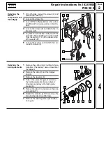
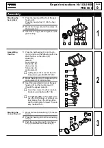
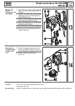
1
Loosen the screw (8) and remove the trig-
ger (7) with cover.
2
Loosen both screws (1) and remove the
motor cover (2).
3
Loosen the screws (3) and (5) and the dis-
tance sleeve (6).
4
Remove the complete handle (4).
Dismantling the
auxiliary handle
1
Loosen the screw (2), remove the fan type
lock washer (1) and unscrew the han-
dle (3).
2
The following parts must be removed:
- screw off the clamping ring (4)
- support (5)
- push out the plastic cover (8),
- screw (7),
- clamping ring (6),
- depth gauge (9).
3
Push back the sleeve (B) and lever off the
cover cap (A).
4
Remove the sleeve (B).
5
Pull the gear housing insulation (C) from
the machine.
1
2
7
8
1
5
2
8
9
A
7
6
3
4
1
B
C
2
Summary of Contents for PHE 50 S
Page 1: ......


