2920 1371 00
5
Instruction book
Oil-free Air Division
is warmed up by the incoming air to approx. 10°C (18°F)
below the incoming air temperature. Reheating the dried air
reduces its relative humidity, so that condensation in the air
net cannot occur unless the air is cooled to below the pressure
dewpoint temperature indicated by gauge (1).
1.3 Refrigeration circuit (Fig. 2)
Compressor (M1) delivers hot, high-pressure refrigerant gas,
which flows, via the coil(s) of liquid separator(s) (7), through
condenser (9) where most of the refrigerant condenses. On
air-cooled condensers, a fan control switch (S3) stops and starts
the fan motor (M2) at falling or rising condenser pressure. On
water-cooled condensers, an automatic valve (3-Fig. 5a)
regulates the cooling water flow, thus controlling the
temperature, which is directly dependent on the pressure. The
cooled refrigerant then collects in receiver (10).
The liquid leaves the receiver (10) via its syphon outlet and
flows through liquid refrigerant dryer (12), via refrigerant/
refrigerant heat exchanger (17) and sight-glass (8), to expansion
valve (13) where it expands to evaporating pressure.
In expansion valve (13) some of the expanding liquid refrigerant
evaporates, for which the required heat is withdrawn from the
refrigerant itself.
The refrigerant enters the heat exchanger/evaporator (15) where
it withdraws heat from the compressed air by further
evaporation. Dependent on the compressed air load, all, or
almost all, refrigerant evaporates at constant pressure and
temperature. The vapour refrigerant leaving evaporator (15)
flows into liquid separator(s) (7) via refrigerant/refrigerant heat
exchanger (17). The liquid separator prevents any droplets
from entering compressor (M1) because warm refrigerant,
leaving the compressor, flows through the coil(s) of the liquid
separator(s) and evaporates the surrounding liquid. From liquid
separator(s) (7) the refrigerant gas is sucked in by the
compressor.
The dryers are provided with a sight-glass (8). The sight-glass
allows to check the refrigerant flow in the line. During normal
operation, the liquid flow must be clear. In general, vapour
bubbles indicate a shortage of refrigerant. Note that fluctuations
in the load may cause bubbles to pass in the flow for a short
time. The center of the glass is provided with a moisture
indicator which is green when the liquid refrigerant is free of
moisture. It will turn into yellow when the refrigerant contains
moisture, indicating that the liquid dryer needs to be replaced.
1.4 Automatic regulation system
(Fig. 2)
Expansion valve (13) maintains the evaporating temperature
between 1 and -1°C (34 and 30°F); these are the approximate
limit temperatures at zero and maximum air load respectively.
At partial or no load, the excess cooling capacity is transferred
in liquid separator(s) (7). The condenser pressure must be kept
as constant as possible to obtain stable operation of expansion
valve (13). Therefore, on air-cooled dryers, fan control switch
(S3) stops and starts cooling fan (M2). On water-cooled dryers,
the temperature is controlled by an automatic regulating valve
on the water circuit. The switch or regulating valve ensures
proper operation at low air load and/or low ambient temperature.
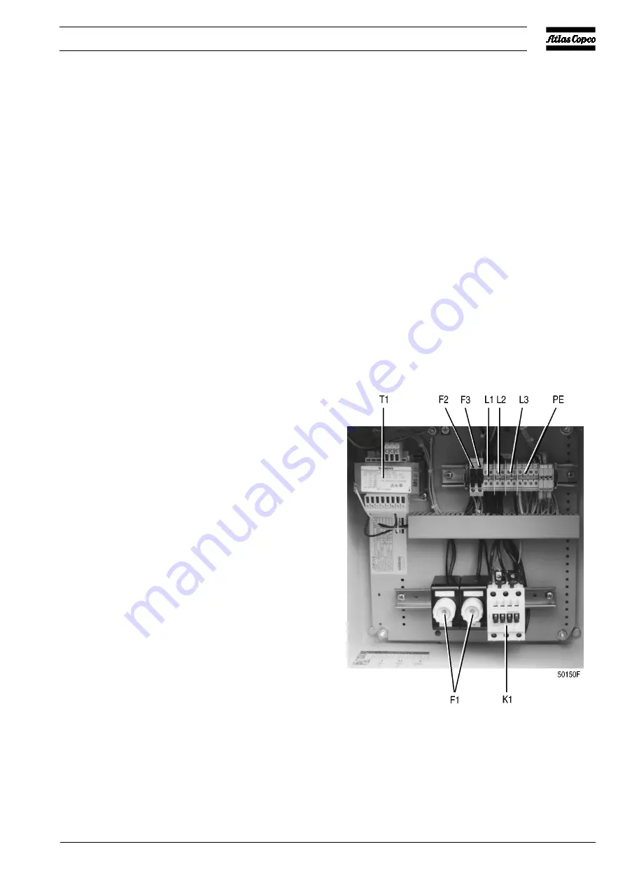
1.5 Electrical system
These dryers are three-phase units.
The refrigerant compressors are equipped with a crankcase
heater. When voltage is supplied, the heater is energized. It
keeps the oil in the crankcase warm to prevent condensing of
refrigerant in the compressor housing, which could result in
serious damage of the compressor at restart (liquid knock).
F1.
Fuses, fan motor
F2/F3. Fuse, secondary side (24 V) of transformer
K1.
Motor contactor, refrigerant compressor
L1/3.
Terminal, mains
PE.
Earth terminal
T1.
Transformer
Fig. 3. Electric cubicle (typical example)
Summary of Contents for FD1200
Page 11: ...2920 1371 00 11 Instruction book Oil free Air Division Fig 6b Dimension drawing of FD560 W...
Page 12: ...2920 1371 00 12 Oil free Air Division Instruction book Fig 6c Dimension drawing of FD700...
Page 13: ...2920 1371 00 13 Instruction book Oil free Air Division Fig 6d Dimension drawing of FD700 W...
Page 16: ...2920 1371 00 16 Oil free Air Division Instruction book Fig 6g Dimension drawing of FD1600 W...


