6
IWTS-14 SR and 30 SR High Performance In-Wall Surround Speakers
Speaker Installation
NOTE:
We always recommend a professional be involved in the instal-
lation of the IWTS SRs.
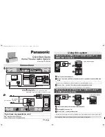
Installation of the IWTS SRs in New Construction
with Optional Bracket
For new construction, we highly
recommend that you use the
optional IN-NC-14/30SR New
Construction Bracket.
The lip on the New Construc-
tion Bracket must face outwards
into the room. Sheetrock is then
installed up to the lip, leaving a
perfectly-defined mounting hole
for the speakers.
Use a level to get it straight; this
can't be fixed later.
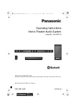
Installation of the IWTS-14 SR and 30 SR in
Existing Construction
The IWTS SRs can be easily
mounted in most any stan-
dard wall material, from ½ to
1½ inches thick. The IWTS SR
rotating wall clamps firmly fix
it to the wall surface after the
proper cutout has been made.
An important precaution to
take before mounting:
Keep the top and bottom of
the actual mounting hole at
least 1½ inches away from
beams or studs to ensure that
the clamps have adequate
room to rotate. A crossbrace
or other obstruction that’s
too close will stop them from
properly doing their job.
Removing and Installing the Grille
Remove the grille from the speaker using an awl or the point of a drywall
screw in a grille opening near one of the grille corners. Slowly pry the grille
out, being careful not to damage the speaker’s frame or its finish.
To re-install the grille later, press it carefully into the appropriate opening in
the frame assembly. Since it’s designed to fit snugly, please take your time
and use care when installing the grille.
Cutting the Opening
Speaker Installation
After determining the best location for the speaker as outlined above, use
the enclosed template to cut the proper size hole.
10¾ x 14¼” (273 x 362mm)
WARNING:
Exercise extreme care before making any wall cuts to
ensure that you will not cut through any wires, pipes, or other items
that may be in the wall. You may sometimes, but not always, be able
to determine the approximate location of wires and pipes by looking
at the locations of nearby outlets and plumbing. But their location or
absence is never an assurance that there is not something within the
wall cavity.
14
1
⁄
4
”
(362mm)
015-1214
10
3
⁄
4
”
(273mm)
IWTS-14 SR
and IWTS-30 SR
Mounting Template