Technical Manual & Parts Lists
15
LAST CORNER ADJUSTMENTS:
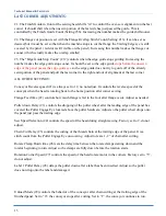
#1. The Finish Guide in front of the sewing head shifts “in” to control the over-sew alignment on the last
corner. It should shift when the unsewn portion of the last side has just passed the guide. This is
controlled by the Finish Guide Count (Setting #36). Increasing the number makes the guide shift sooner.
#2. The flange cut position is set with the Flange Overlap Stitch Count (Setting #13). It can be set as
desired, but it must be set so that when the machine stops to cut the flange the Trailing Edge eye is still
covered by the panel ( red dot is still visible on the panel). Increasing this number makes the flange cut
sooner (which actually makes the overlap smaller)
#3. The “Edge Guide Stop Count” (#12) controls when the edge guide stops guiding. Increasing the
number makes the edge guide stop sooner. It should be set so the edge guide
stops before the unsewn
edge of the panel passes the edge guide eye
so the edge guide does not try to guide off of the already
sewn portion of the panel and pull the last corner to the right and out of alignment at the last corner.
ALL OTHER SETTINGS:
Conveyor Reverse speed (#1) is always set to 12, no not adjust. It controls the reverse speed of the
conveyor when the head is rotating back to the home position after corner sewing.
Flange Feed time (#2) controls how much flange is fed to the foot after flange is cut. Adjust as needed.
Puller down Delay (#3) controls the dropping of the puller wheel after the leading edge of the panel has
covered the Puller Engage Eye located above the puller hardware. Adjust so the puller wheel drops onto
the panel just pass the trailing edge.
Sew Speed Selection (#4) controls the speed of the head during straight sewing. Factory set to 2, do not
adjust.
Chain Cut Delay (#5) controls the cutting of the thread chain at the trailing edge of the panel. It is a
stitch count from the Puller Engage Eye uncovering. Adjust to leave 1-2” of chain after cutting.
Rotate Clamp Down time (#6) sets the delay time between the rotate clamps starting down and the
rotator beginning to turn. Adjust so the clamps are fully down before the rotation starts.
Rotation Corner Speed (#7) controls the speed of the head rotate motor in the corners. Factory set to “3”,
do not adjust.
Label 1 Puller Delay (#8) delays the puller down after a label has been inserted. Adjust so the puller
does not drop onto the label and damage it
Unload Mode (#9) controls the behavior of the conveyor after chain cutting at the trailing edge of the
finished panel. Set to “0”, the conveyor stops after cutting. Set to “1”, the conveyor continues to run,
Summary of Contents for 1317A
Page 2: ...Technical Manual Parts Lists 1 ...
Page 28: ...Technical Manual Parts Lists 23 ...
Page 30: ...Technical Manual Parts Lists 25 ...
Page 32: ...Technical Manual Parts Lists 27 ...
Page 34: ...Technical Manual Parts Lists 29 ...
Page 36: ...Technical Manual Parts Lists 31 ...
Page 39: ...Technical Manual Parts Lists 34 ...
Page 40: ...Technical Manual Parts Lists 35 ...
Page 42: ...Technical Manual Parts Lists 37 ...
Page 44: ...Technical Manual Parts Lists 39 ...
Page 48: ...Technical Manual Parts Lists 43 ...
Page 50: ...Technical Manual Parts Lists 45 ...
Page 51: ...Technical Manual Parts Lists 46 1318112 1 CONTROL PANEL AAC Drawing Number 1318112 Rev 2 ...
Page 52: ...Technical Manual Parts Lists 47 ...
Page 55: ...Technical Manual Parts Lists 50 ...
Page 56: ...Technical Manual Parts Lists 51 ...
Page 60: ...Technical Manual Parts Lists 55 ...
Page 63: ...Technical Manual Parts Lists 58 ...
Page 64: ...Technical Manual Parts Lists 59 ...
Page 71: ...Technical Manual Parts Lists 66 ...
Page 72: ...Technical Manual Parts Lists 67 ...
Page 79: ...Technical Manual Parts Lists 74 ...
Page 81: ...Technical Manual Parts Lists 76 ...
Page 83: ...Technical Manual Parts Lists 78 ...
Page 85: ...Technical Manual Parts Lists 80 1318356 CONVEYOR SUB ASSY 2 AAC Drawing Number 1318356 Rev 0 ...
Page 88: ...Technical Manual Parts Lists 83 ...
Page 89: ...Technical Manual Parts Lists 84 ...
Page 92: ...Technical Manual Parts Lists 87 ...
Page 93: ...Technical Manual Parts Lists 88 ...
Page 98: ...Technical Manual Parts Lists 93 ...
Page 100: ...Technical Manual Parts Lists 95 ...
Page 102: ...Technical Manual Parts Lists 97 ...
Page 104: ...Technical Manual Parts Lists 99 1317A PSM PROGRAM SETTINGS MAP ...
Page 105: ...Technical Manual Parts Lists 100 1317A WD WIRNG DIAGRAM CNTRL PNL ...
Page 106: ...Technical Manual Parts Lists 101 1317A PD PNEUMATIC DIAGRAM 1317A ...
Page 107: ...Technical Manual Parts Lists 102 ...


