background image


  8         


ATD100N User Guide


Operation Guide 

1.


Serial Mode 

When the device is set to Serial mode, the device uses the ATID protocol to communicate with the HOST 
device in a command. In order to connect the host device to the device, a demo program provided by 
ATID or a program developed using SDK is required.  


2.


Product operation in serial mode 

1)


When the USB cable of the product is connected to the Windows Host device, the product turns 

on with a buzzer sound. 

2)


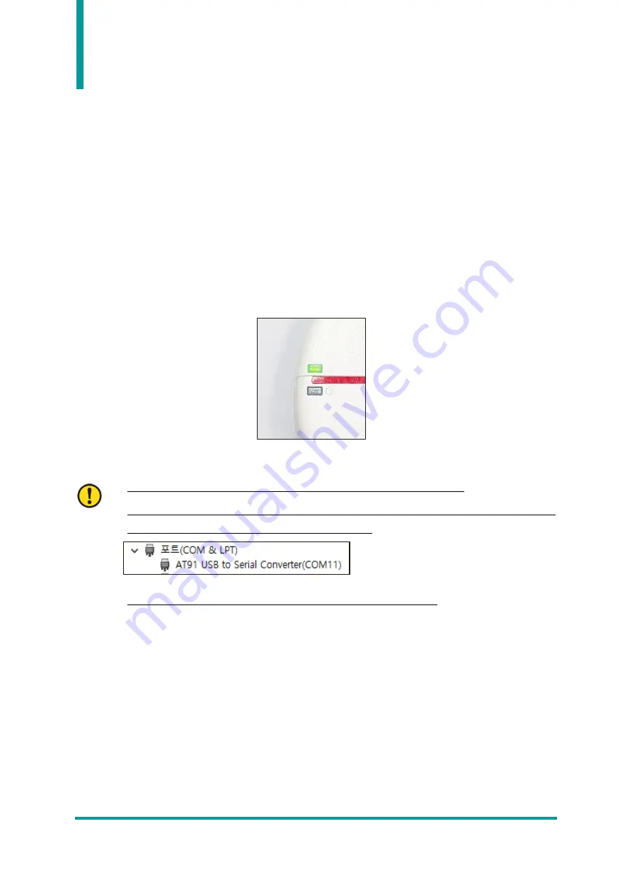
When booting is normally completed, ‘Status LED 2’ blinks in green

.  


3)


When connected to Windows Host without problems, the device is assigned a COM port.  


COM Port is assigned a different number depending on the PC situation. 


Check  the  COM  Port  number  assigned  to  the 

AT91  USB  to  Serial  Converter

  in 

Device 

Manager 

 Ports (COM & LPT)

 of the control panel. 


Depending on the PC situation, driver installation may be required. 


4)


When the program of Windows Host device and ATD100N are connected, ‘Status LED 2’ stops 

blinking and stays on. 

5)


If  data  collection  starts 

while  the  demo  program  is  connected,  ‘Status  LED  1’  blinks  in  red 

depending on whether there is data or not.


6)


Press and hold the power switch or unplug the USB cable from the host device to turn off the 

product.


Summary of Contents for ATD100N

Page 1: ...ATD100N USER GUIDE ATID Co Ltd Ver 0 1 ...

Page 2: ... USB CABLE 7 3 UHF ANTENNA 7 OPERATION GUIDE 8 1 SERIAL MODE 8 2 PRODUCT OPERATION IN SERIAL MODE 8 3 HID HUMAN INTERFACE DEVICES MODE 9 4 PRODUCT OPERATION IN HID MODE 9 USING THE WINDOWS HOST DEMO APPLICATION 10 SDK SOFTWARE DEVELOPMENT KIT 11 PRODUCT WARRANTY 12 1 ATD100N PRODUCT DETAILS 12 2 SDK DOWNLOAD 12 3 WARRANTY AND TECHNICAL SUPPORT 12 4 CERTIFICATIONS 12 ...

Page 3: ...irmware changes of product Ownership of text images logos product name in user guide is included in writer and some parts of text images logos product name in the user guide were borrowed for user s understanding at random if there is a legal restriction such as a copyright law it will be redistributed after adjustment Product Overview ATD100N is a compact size UHF RFID desktop reader product This...

Page 4: ...dule of PHYCHIS was applied to read write the UHF RFID tag 3 Using the USB cable installed in the device it is possible to connect to a Host device to operate and transmit data 4 It is possible to check the operation status of the device through the LED and buzzer 5 Support HID Human Interface Device mode ...

Page 5: ...HID Standard I O Port USB Client Notification LED Indicator Buzzer Data Collection RFID UHF Protocol EPC GEN2 ISO IEC 18000 6C Reading Range 50 cm Depending on environment and tag type Writing Range 50 cm RF Output 0 5W Frequency Range US FCC EU CE KR KC JP TELEC 902MHz 928MHz 865MHz 868MHz 917MHz 921MHz 920MHz 923MHz 0 2W Antenna Circular Antenna 2 2 dBic User Environment Operating Temp 10 C to 5...

Page 6: ...icate the status of the product 2 Status LED 2 LED indicating the status of the product 3 Mode Setting Switch The operation mode of ATD100N is set according to the switch setting as shown table below If user changes the operation mode the setting is applied as the product reboots Switch Setting Operation Mode S Serial H HID Status LED 2 Mode Setting Switch Serial HID Power Button Status LED 1 ...

Page 7: ...nection 3 UHF Antenna The antenna of ATD100N is located in the center of the product The closer the tag is located at the center of the product the higher the recognition rate Two types of antennas 866MHzk 912MHz are supported according to each country s frequency range It is necessary to select an antenna according to the region where the product is used USB TYPE A UHF Antenna ...

Page 8: ...links in green 3 When connected to Windows Host without problems the device is assigned a COM port COM Port is assigned a different number depending on the PC situation Check the COM Port number assigned to the AT91 USB to Serial Converter in Device Manager Ports COM LPT of the control panel Depending on the PC situation driver installation may be required 4 When the program of Windows Host device...

Page 9: ...evice the product turns on with a buzzer sound 2 When booting is normally completed Status LED 1 turns green and Status LED 2 blinks in red When connected to Host Status LED 2 stops blinking and stays on 3 When connected to the host data collection starts automatically 4 When data collection starts status LED 1 blinks in orange depending on whether there is data or not 5 Data collected in HID mode...

Page 10: ...1 To connect ATD100N and Windows Host device connect via USB 2 User can install the demo app included in the SDK on the host device For details on how to use the Windows demo application refer to the ATID Reader Demo Guide for Windows document included in the SDK ...

Page 11: ...vided by ATID Platform Development Tool Development Language Windows Visual Studio NET Framework C UWP C SDK Package Configuration Details Demo Demo Application Doc Development documents such as user guides manuals programmer guides demo guides etc Lib Library for application development Sample Sample Code USB Drive for Windows Windows USB Driver of ATID Bluetooth Reader ...

Page 12: ...se shall be repaired even during the free repair period For warranty technical support and inquiries on this product please contact the distributor or ATID 4 Certifications This product is KC FCC CE and TELEC certified but we are not responsible for any issues arising during use outside of the certified area For details please contact the distributor or ATID ATID Address 1402 83 Gasan Digital 1ro ...

Reviews: