background image

Manual, Robotic Tool Changer Teaching Aids
Document #9610-20-1419-07

Pinnacle Park • 1041 Goodworth Drive • Apex, NC 27539 USA • Tel: +1.919.772.0115 • Fax: +1.919.772.8259 • www.ati-ia.com 

16

6.  Serviceable Parts

6.1  Tool Teaching Aid Serviceable Parts

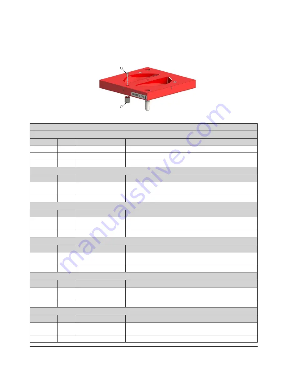
Figure 6.1—Tool Teaching Aid Plate (QC-210 Shown)

2            

                1

Table 6.1—Tool Teaching Aid Plate

QC-40

ITEM NO.

QTY

PART NUMBER

DESCRIPTION

1

4

3710-20-3484

Magnet, 0.625’’ x .18’’ K&J Magnets MMS-H-A

2

2

3500-1010050-21

#4-40 x 1/2 Stainless Steel Socket Head Cap Screw

3

2

3500-1010062-1

#4-40 x 5/8 Socket Head Cap Screw

QC-110, QC-210 

ITEM NO.

QTY

PART NUMBER

DESCRIPTION

1

3

3710-20-3355

Encased Alinco 5 Magnet 1/2” Dia, 1/2” Thick, 6-32 Hole, 1.4 

Pull lbs

2

3

3500-1215037-21

#6-32 x 3/8” Stainless Steel Flat Head Socket Cap Screw

QC-160, QC-213 

ITEM NO.

QTY

PART NUMBER

DESCRIPTION

1

4

3710-20-3355

Encased Alinco 5 Magnet 1/2” Dia, 1/2” Thick, 6-32 Hole, 1.4 

Pull lbs

2

4

3500-1215037-21

#6-32 x 3/8” Stainless Steel Flat Head Socket Cap Screw

QC- 310

ITEM NO.

QTY

PART NUMBER

DESCRIPTION

1

6

3710-20-3355

Encased Alinco 5 Magnet 1/2” Dia, 1/2” Thick, 6-32 Hole, 1.4 

Pull lbs

2

6

3500-1215037-21

#6-32 x 3/8” Stainless Steel Flat Head Socket Cap Screw

QC-510

ITEM NO.

QTY

PART NUMBER

DESCRIPTION

1

8

3710-20-3355

Encased Alinco 5 Magnet 1/2” Dia, 1/2” Thick, 6-32 Hole, 1.4 

Pull lbs

2

8

3500-1215037-21

#6-32 x 3/8” Stainless Steel Flat Head Socket Cap Screw

QC-1210 

ITEM NO.

QTY

PART NUMBER

DESCRIPTION

1

9

3710-20-3355

Encased Alinco 5 Magnet 1/2” Dia, 1/2” Thick, 6-32 Hole, 1.4 

Pull lbs

2

9

3500-1215037-21

#6-32 x 3/8” Stainless Steel Flat Head Socket Cap Screw

Summary of Contents for QC-1210 Series

Page 1: ...tivity Pinnacle Park 1041 Goodworth Drive Apex NC 27539 USA Tel 1 919 772 0115 Fax 1 919 772 8259 www ati ia com Tool Changer Teaching Aid Assemblies QC 40 QC 110 QC 160 QC 210 QC 213 QC 310 QC 510 an...

Page 2: ...ubject to change without notice This manual is periodically revised to reflect and incorporate changes made to the product The information contained herein is confidential and reserved exclusively for...

Page 3: ...re 9 4 Maintenance 13 5 Troubleshooting and Service Procedures 14 5 1 Troubleshooting Procedures 14 5 2 Service Procedures 15 5 2 1 Adjustment or Installation of Magnets in Tool Teaching Aid Assembly...

Page 4: ...anations of the notifications found in this manual and safety precautions that apply to the product More specific notifications are imbedded within the sections of the manual where they apply 1 1 Expl...

Page 5: ...sides is a pinch point All personnel should be prevented from placing any part of their body or clothing in the gap especially during actuation of the locking mechanism The customer is responsible for...

Page 6: ...can occur with the Tool not placed and energized circuits on Place the Tool in the tool stand turn off and discharge all energized circuits purge all pressurized connections and verify all circuits ar...

Page 7: ...to Section 8 Drawings for more information 2 1 Master Teaching Aid The Master Teaching Aid assembly is a red anodized aluminum body The center interior has a tapered feature that engages with the Tool...

Page 8: ...Aid Assembly 9005 20 2317 4 6 32 x 3 8 Flat Head Socket Cap Screw 2 Alignment Pin QC 210 Tool Teaching Aid Assembly 9005 20 1379 2 Alignment Pin 3 6 32 x 3 8 Flat Head Socket Head Cap Screw QC 210 Mas...

Page 9: ...ign a Teaching Aid complete the following procedure 1 Place the Tool plate in the tool stand Robot programs should be written with the Tool plate resting in the Tool stand 2 Orient the Tool side Teach...

Page 10: ...nnel from placing any body part or clothing in the gap especially during actuation of the locking mechanism 5 Orient the Master side Teaching Aid such that the A flat corresponds to the A flat on the...

Page 11: ...h the A flat on the Tool plate Figure 3 3 Positioning the Master plate towards the Tool plate Master Teach Aid Flat IDs must match Flat A shown Tool Teach Aid Tool Aid face must be parallel with the M...

Page 12: ...ing Aid and unlock the Tool Changer 12 Remove the Master and Tool Teaching Aids from the Tool Changer NOTICE Refer to the applicable Tool Changer manual for the maximum recommended offsets Depending o...

Page 13: ...the exposure of the Tool Changer and Teaching Aid to this environment Cover idle Tool assemblies and Teaching Aids to prevent debris from settling on the mating surface Keep the Tool Changer s Master...

Page 14: ...all circuits are de energized before performing maintenance or repair s on the Tool Changer or modules 5 1 Troubleshooting Procedures Troubleshooting information is in the following table Table 5 1 Tr...

Page 15: ...wrench Supplies required Loctite Primer 7649 and Loctite 262 1 Remove the 6 32 x 3 8 socket flat head cap screw s in the Tool Refer to Figure 5 1 2 Remove the existing magnet if necessary 3 Place new...

Page 16: ...3500 1215037 21 6 32 x 3 8 Stainless Steel Flat Head Socket Cap Screw QC 160 QC 213 ITEM NO QTY PART NUMBER DESCRIPTION 1 4 3710 20 3355 Encased Alinco 5 Magnet 1 2 Dia 1 2 Thick 6 32 Hole 1 4 Pull l...

Page 17: ...Aluminum N A N A 9120 210 TEACH QC 210 Teaching Aids 6061 T6 Aluminum 5 5 lb 2 49 kg 2 2 in 55 mm 9005 20 1380 QC 210 Master Side Teaching Aid 6061 T6 Aluminum N A N A 9005 20 1379 QC 210 Tool Side T...

Page 18: ...ION 1 1 9005 20 8801 QC 40 Master Side Teaching Aid 2 1 9005 20 8803 QC 40 Tool Side Teaching Aid B 2 3 1 2 REVISION NOTES UNLESS OTHERWISE SPECIFIED DO NOT SCALE DRAWING ALL DIMENSIONS ARE IN MILLIME...

Page 19: ...IDE AIDS ARE APPROXIMATELY 1MM APART STEP 6 ADJUST THE POSITION OF THE ROBOT TO CORRECT FOR ANY LATERIAL MISALIGNMENT USE THE EDGES OF THE TEACHING AID TO ALIGN THE TOOL SIDE AND MASTER SIDE Z Directi...

Page 20: ...A Tool etc Step 1 Place the Tool Plate in the Tool Stand Programs should be written with the Tool Plate resting in the Tool Stand Step 5 Move the Master Plate Assembly slowly downward until the Master...

Page 21: ...e Bushings Orient the Tool Plate by inserting the Locating Pins Mount the Tool Side Aid over the Tool Aid in place Mount the Master Side Aid to the QC Master Plate ensuring Energize the Locking Mechan...

Page 22: ...er and Tool Flat ID s match These faces must be parallel 1mm Step 5 Move the Master Plate Assembly slowly downward until the Master and Tool Side Aids are approximately 1mm apart Step 6 Adjust the pos...

Page 23: ...ID s correspond i e A Master to A Tool etc Step 6 Adjust the position of the robot to correct for any lateral misalignment Use the Alignment Marks to align the Tool Side and Master Side Aids Step 7 R...

Page 24: ...Side QC 510 Teaching Aid 3 1 9121 510DM 0 0 0 0 Base Assembly Master QC 510 4 1 9121 510DT 0 0 0 0 BASE ASSEMBLY TOOL QC 510 B 1 4 1 2 REVISION NOTES UNLESS OTHERWISE SPECIFIED DO NOT SCALE DRAWING AL...

Page 25: ...D DO NOT SCALE DRAWING ALL DIMENSIONS ARE IN MILLIMETERS DRAWN BY CHECKED BY L Strahler 6 9 15 D Norton 6 10 15 TITLE SCALE SIZE DRAWING NUMBER PROJECT SHEET OF 9230 20 7827 150430 1 01 PROPERTY OF AT...

Page 26: ...ld be parallel to the Tool Plate Assembly s face Ensure that the orientation of the Master and Tool Assemblies are such that the Flat Alignment marks correspond Alignment marks Step 1 Place the Tool i...

Page 27: ...the correct Pick up and Replacement coordinates be determined Perform the following calculation to determine the Pick up and Replacement location Z Pick up Coordinate Z Coordinate from Step 6 70mm Ens...

Page 28: ...t varying or extending the warranty and limitation of remedy provisions contained herein is authorized by ATI and may not be relied upon as having been authorized by ATI unless in writing and signed b...

Reviews: