background image

4. 

 INSTALLATION


ENGLISH 


Pag.7 / 9 

 Before filling the solar circuit, it is advisable to provide a pressure reducer if the mains pressure exceeds 6 

bar. 
 

4.6 

POSITIONING 

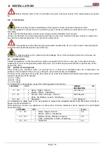
 When selecting the place of installation of the appliance, follow the safety instructions below: 

- Place the appliance in places where it is possible to prevent access by children as a potential source of danger for 
their safety. 
- Make sure that the fastening is carried out according to what is illustrated in this manual. 
- Make sure that there are no high temperature parts that can come into contact with people, animals or objects that 
are sensitive to high temperatures: if not, provide for safety fences 


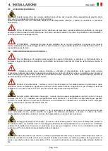
The appliance must be lifted using the appropriate handles (FIG_04-2) in order to avoid compromising the 

seal of the black seal that seals the cup and the tray. 

 It must be positioned in a place where the breakage of any of the elements provided can not cause any 

damage to people or things. 

4.7 

ORIENTATION 

Position the appliance so that the capturing surface is exposed to the South or in any case in the east-south-west 
quadrant (FIG_04-3) avoiding shading areas (FIG_04-4). The north-facing exposure affects the performance of the 
panels (FIG_04-5). 

4.8 

 GRADE OF INCLINATION 

When  choosing  the  inclination  (when  not  required  due  to  a  sloped  roof  installation)  take  into  consideration:  the 
variation of the inclination of the sun's rays during the year and the location of installation. 
The holes on the solar panel frame (FIG_04-6) allow you to reach three different inclinations depending on the location 
where the appliance will be installed: 
- A-A: 11 ° tilting 
- B-B: 28 ° tilting 
- C-C: 36 ° tilting 
For installations on flat surfaces, respect the following grade of inclinations: 

LATITUDE 

CITY 

GRADE 

OF 

INCLINATION 

0 ° .. 43 °  


Rome - Napoli - Catania 


Madrid - Athens - Casablanca 

A-A: tilting 11 ° 

43 °.. 54 °  


Bolzano - Milan - Bologna - Florence 


Paris - Amsterdam - London - Wuerzburg 

B-B: tilting 28 ° 

54 °.. 65 °  


Stockholm 

C-C: tilting 36 ° 

For  installations  on  tilting  roofs,  if  it  is  not  possible  to  recreate  the  installation  similar  to  the  flat  surface  (FIG_04-7), 
always use the inclination A-A 
When  installing  more  than  one  appliance  on  a  flat  surface,  minimum  distances  must  be  respected  to  avoid  shaded 
areas (FIG. 04-8). 

LATITUDE 

CITY 

D. min 

0 °.. 43 °  


Rome - Napoli - Catania 


Madrid - Athens - Casablanca 

2 m 

43 °.. 54 ° 


Bolzano - Milan - Bologna - Florence 


Paris - Amsterdam - London - Wuerzburg 

3 m 

54 °.. 65 ° 


Stockholm 

4 m 


Summary of Contents for DISCOSOL - 200

Page 1: ...RMICO COMPATTO AD ACCUMULO DIRETTO PER IL RISCALDAMENTO DELL ACQUA SANITARIA INSTRUCTION MANUAL COMPACT SOLAR WATER HEATER DIRECT STORAGE FOR HEATING SANITARY WATER MANUAL DE INSTRUCCIONES CALENTADORES DE AGUA SOLAR TÉRMICA LA ACUMULACIÓN DE CALEFACCIÓN DIRECTA DE AGUA SANITARIA ...

Page 2: ...210 0050_figure docx FIG_02 1 FIG_02 2 FIG_02 3 FIG_04 1 FIG_04 2 FIG_04 3 FIG_04 4 FIG_04 5 FIG_04 6 FIG_04 7 FIG_04 8 ...

Page 3: ...le 1 3 TRATTAMENTODELL ACQUA In presenza di acqua con durezza superiore ai 15 F si consiglia l utilizzo di dispositivi anticalcare la cui scelta deve avvenire in base alle caratteristiche dell acqua 1 4 INFORMAZIONI DA FORNIRE ALL UTENTE A CURA DELL INSTALLATORE L utente deve essere istruito sull utilizzo e sul funzionamento del proprio impianto solare In particolare è compito dell installatore Co...

Page 4: ...ertenze contenute nel libretto in quanto forniscono importanti indicazioni riguardanti la sicurezza di installazione l uso e lamanutenzione Conservare con cura il libretto per ogni ulteriore consultazione L installazione e la manutenzione devono essere effettuate in ottemperanza alle norme vigenti secondo le istruzioni del costruttore e da personale qualificato ed abilitato ai sensi di legge Per p...

Page 5: ...ressione protegge il serbatoio da possibili pressioni eccessive causate dall espansione dell acqua durante il riscaldamento Automaticamente senza l assistenza di energia diversa da quella del fluido caldo in pressione scarica una quantità di fluido tale da impedire che siano superati i limiti di pressione e temperatura prefissati a protezione dei serbatoi di accumulo Taratura 700 kpa 92 C H uscita...

Page 6: ...mento dovrà essere esibito al personale del Centro Assistenza Tecnico autorizzato in caso di intervento Assicurarsi che sul collettore solare vengano effettuati periodici interventi di controllo e manutenzione e che tali interventi vengano registrati A tale proposito si suggerisce di stipulare un contratto di manutenzione Conservare il libretto e tutta la documentazione relativa al prodotto Se l a...

Page 7: ...ione mettere a terra il circuito solare per la compensazione di potenziale e quale protezione contro sovratensioni Applicare ai tubi del circuito solare fascette stringitubo con viti di messa a terra da collegare con un cavo in rame di 16 mm 2 ad una barra di compensazione del potenziale Corretto utilizzo della scala d appoggio le scale devono essere appoggiate su punti sicuri ad un angolo compres...

Page 8: ...nti Impianti prefabbricati Parte 2 Metodi di prova UNI EN 1991 2004 parti 1 2 1 3 e 1 4 Azioni sulle strutture carichi di neve e carichi del vento ENV 61024 1 ENV 12977 2 Protezione di strutture contro i fulmini Parte 1 Principi generali IEC 1024 1 1990 modificata UNI 9711 Impianti termici utilizzanti energia solare Dati per l offerta l ordinazione e collaudo D P R n 412 Regolamento recante norme ...

Page 9: ...ne nera che sigilla cupole e vassoio Deve essere posizionato in un luogo nel quale la rottura di uno qualsiasi degli elementi forniti non possa generare alcun danno alle persone o alle cose 4 7 ORIENTAMENTO Posizionare l apparecchiò in modo che la superficie captante sia esposta verso sud o comunque nel quadrante est sud ovest FIG_04 3 evitando zone di ombreggiamento FIG_04 4 L esposizione rivolta...

Page 10: ...la nonché per la validità della garanzia la suddetta valvola di non ritorno non deve in alcun modo essere isolata ostruita o coperta 4 10 COLLEGAMENTO ELETTRICO Nei modelli DS11 e DS12 è presente una resistenza elettrica già montata a corredo dell apparecchio FIG_04 10 L utilizzatore deve predisporre o far predisporre da un tecnico qualificato una presa di alimentazione bipolare con terra a valle ...

Page 11: ...zato Durante la manutenzione porre attenzione a tutte le disposizioni di sicurezza riportate nei paragrafi precedenti 5 3 RICAMBI vedi FIG_05 1 POS CODICE DESCRIZIONE U M DS01 DS02 DS11 DS12 01 0 0038 cavallotto NR 1 1 1 1 02 0 0056 piastra laterale sinistra NR 1 1 1 1 03 0 0069 staffa per telaio NR 4 4 4 4 04 0 0070 piastra laterale destra NR 1 1 1 1 05 0 0083 rondella per tubo anodo NR 1 1 1 1 0...

Page 12: ...llowed 1 3 WATER TREATMENT When water is with hardness higher than 15 F we recommend the use of descaling devices the choice of which must be made based on the characteristics of the water 1 4 INFORMATION TO BE SUPPLIED BY THE INSTALLER TO THE USER The user must be instructed on the use and operation of the solar system In particular it is the installer s job Deliver to the user these instructions...

Page 13: ...ead the warnings contained in the booklet as they provide important information regarding the safety of installation use and maintenance Keep the booklet with care for any further consultation Installation and maintenance must be carried out in compliance with the regulations in force according to the manufacturer s instructions and by qualified personnel authorized by law Professionally qualified...

Page 14: ... from possible excessive pressures caused by expansion of the water during heating Automatically without the assistance of energy other than that of the hot pressurized fluid it discharges a quantity of fluid such as to prevent the preset pressure and temperature limits to protect the storage tanks from being exceeded Calibration 700 kpa 92 C H Hot water outlet I Cold water inlet 2 2 DIMENSIONS AN...

Page 15: ... the product This document must be presented to the authorized technical assistance center staff in case of intervention Ensure that periodic checks and maintenance are carried out on the solar panel and that these interventions are recorded In this regard it is suggested to stipulate a maintenance contract Keep the booklet and all the documentation related to the product If the appliance should b...

Page 16: ... of installation Danger of overvoltage earth the solar circuit for potential equalization and to protect against overvoltage Apply pipe clamps to the solar circuit pipes with earthing screws to be connected with a 16 mm2 copper cable to a potential equalization bar Correct use of the support ladder the ladders must be placed on safe points at an angle between 65 and 75 respect a ledge of the ladde...

Page 17: ...on and maintenance of heating systems in buildings Law no 46 Safety standards relating to systems Presidential Decree no 447 Regulations for the implementation of the law 5 March 1990 n 46 regarding plant safety Standards Decree 311 Implementation of EC directives on the energy performance of buildings 4 4 PACKING The Discosol is supplied completely assembled The instructions booklet FIG_04 1 is f...

Page 18: ... FIG_04 3 avoiding shading areas FIG_04 4 The north facing exposure affects the performance of the panels FIG_04 5 4 8 GRADE OF INCLINATION When choosing the inclination when not required due to a sloped roof installation take into consideration the variation of the inclination of the sun s rays during the year and the location of installation The holes on the solar panel frame FIG_04 6 allow you ...

Page 19: ... the validity of the guarantee the aforementioned non return valve must in no way be insulated obstructed or covered 4 10 ELECTRICAL CONNECTION In the DS11 and DS12 models there is an electrical resistance already mounted in the appliance FIG_04 10 The user must prepare or have a qualified bipolar power supply socket fitted to the ground after a switch disconnected with a key or equivalent disconn...

Page 20: ...e pay attention to all the safety instructions given in the previous paragraphs 5 3 SPARE PARTS see FIG_05 1 POS CODE DESCRIPTION DS01 DS02 DS11 DS12 01 0 0038 staple u bolt No 1 1 1 1 02 0 0056 left side plate No 1 1 1 1 03 0 0069 frame bracket No 4 4 4 4 04 0 0070 right side plate No 1 1 1 1 05 0 0083 washer for anode tube No 1 1 1 1 06 0 0233 earth ring No 1 1 07 0 0292 front plate No 1 1 1 1 0...

Page 21: ... el uso de dispositivos de descascarillado la elección de los cuales debe tener lugar de acuerdo con las características del agua 1 4 INFORMACIÓN QUE SE PROPORCIONA instalador El usuario debe ser instruido en el uso y funcionamiento de su sistema solar En particular el instalador Deje el usuario estas instrucciones así como otra literatura con respecto a este aparato colocado dentro del sobre cont...

Page 22: ...n importante sobre la seguridad de instalación uso y mantenimiento Mantenga este manual para futuras referencias La instalación y el mantenimiento deben ser realizados de acuerdo con la normativa vigente de acuerdo con las instrucciones del fabricante y por personal cualificado y autorizado por la ley para personal profesional cualificado significa que tienen la competencia técnica específica en e...

Page 23: ...tege el tanque de posibles presiones excesivas causadas por la expansión del agua durante el calentamiento Automáticamente sin la ayuda de energía diferente de la del fluido caliente bajo presión descargar una cantidad de fluido tal como para evitar que se superen los límites de presión y temperatura predeterminadas para proteger los tanques de almacenamiento Calibración 700 kPa 92 C H salida de a...

Page 24: ...documento se debe demostrar que el personal del centro de asistencia técnica autorizado en caso de intervención Asegúrese de que el colector solar se lleva a cabo la inspección y el mantenimiento periódico y que este tipo de intervenciones se registran En este sentido se sugiere entrar en un contrato de servicio y mantenimiento Mantenga el folleto y toda la documentación relacionada con el product...

Page 25: ...ierra del circuito solar para la compensación de potencial y como protección contra sobretensiones Aplicar a las tuberías de las abrazaderas de tubo circuito solares con tornillos de tierra para conectar con un cable de 16 mm2 de cobre a una barra de compensación de potencial El uso correcto de la escala de apoyo las escaleras deben colocarse en puntos seguros en un ángulo entre 65 y 75 cumplir co...

Page 26: ...istemas solares térmicos y sus componentes Productos manufacturados de sistemas Parte 2 Métodos de ensayo UNI EN 1991 2004 acciones 1 2 1 3 y 1 4 Acciones en estructuras cargas de nieve y las cargas de viento ENV ENV 61024 1 12977 2 Protección de estructuras contra el rayo Parte 1 Principios generales IEC 1024 1 1990 modificada UNI 9711 Las centrales térmicas utilizan la energía solar Los datos co...

Page 27: ...ebe estar situado en un lugar en el que la rotura de cualquiera de los elementos proporcionados no puede generar ningún daño a personas o cosas 4 7 ORIENTACIÓN Coloque la comida conjunto de manera que la superficie absorbente está expuesto al sur o al menos el este y el sur oeste FIG_04 3 áreas evitando de sombreado FIG_04 4 La exposición orientada al norte afecta al rendimiento de los paneles FIG...

Page 28: ...de la válvula así como para la validez de la garantía la válvula antirretorno antes mencionada no debe ser aislada obstruida o cubierta de ninguna manera 4 10 CONEXIÓN ELÉCTRICA En los modelos DS11 y DS12 es una resistencia eléctrica ya montado suministrado con el aparato FIG_04 10 El usuario debe proporcionar o preparar por un técnico cualificado una potencia bipolar de salida con tierra aguas ab...

Page 29: ...iciones de seguridad de los párrafos anteriores 5 3 PIEZAS ver FIG_05 1 POS CÓDIGO DESCRIPCIÓN UM DS01 DS02 DS11 DS12 01 0 a 0038 saltador NR 1 1 1 1 02 0 0056 placa lateral izquierda NR 1 1 1 1 03 0 0069 soporte para el marco NR 4 4 4 4 04 0 0 070 la placa lateral derecha NR 1 1 1 1 05 0 0 083 arandela para el tubo de ánodo NR 1 1 1 1 06 0 0233 anillo para conexión a tierra NR 1 1 07 0 0292 placa...

Page 30: ......

Page 31: ...210 0050_figure docx FIG_04 9 FIG_04 10 FIG_04 11 FIG_05 1 ...

Page 32: ...210 0050 edizione 2019 01 ATI DI MARIANI SRL Via E Mattei 461 Zona Ind Torre del Moro n 4 47522 Cesena FC ITALIA Tel 0547 609711 Fax 0547 609724 web www atimariani it email info atimariani it ...

Reviews: