background image

VT47 

– User Manual


Page 15/43 

1.6. S

ERVICE 

TPMS 

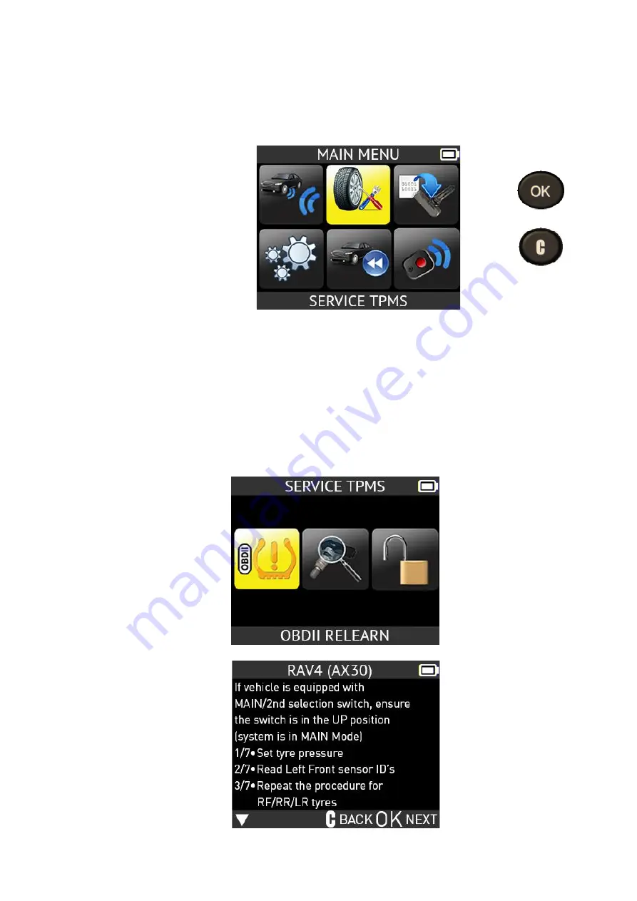
This menu has two main functions. One is to relearn the ID of the 4 sensors into the ECU. 
The other function aims at reading the spare part for all the sensors available by vehicle. 


Select "

SERVICE TPMS

function. 


= continue 


= previous 

  Select car manufacturer. 

  Select car model. 

  Select year. 

1.7. OBDII

 RELEARN


This is for ID relearn to the ECU through the OBDII port. 

  Select the number of wheels 

  Proceed as "

Sensor check

" to trigger all the sensors. 


Summary of Contents for VT47

Page 1: ...USER MANUAL VT47 www ateq tpms com...

Page 2: ...THE USER MANUAL Due to continuing improvements the information contained in this user manual the features and design of this device are subject to be changed without prior notice Edition Revision Ref...

Page 3: ...NSOR 12 1 1 Select Car Manufacturer 12 1 2 Select Car Model 12 1 3 Select year 13 1 4 Select number of wheels and select tire 13 1 5 Test Sensors 14 1 6 Service TPMS 15 1 7 OBDII relearn 15 1 8 Reprog...

Page 4: ...nge Auto Off Settings 31 1 5 Change Zone settings 32 WIFI SETTINGS 33 1 WIFI MENU 33 ABOUT 35 1 ABOUT MENU 35 LANGUAGE 36 1 LANGUAGE MENU 36 MISCELLANEOUS 37 1 CHARGE 37 2 TOOL UPDATE WIFI 38 3 TOOL U...

Page 5: ...er boot Case Material High Impact ABS Radio reception 315 433 MHz Weight 280 g 0 617 lb TPMS tool without rubber cover 449 g 0 989 lb TPMS tool with rubber cover Temperature Operating 4 F to 131 F 20...

Page 6: ...tact us Europe 15 Rue des Dames 78340 Les Clayes s Bois France Phone 33 1 30 80 10 20 E mail emea tpms ateq com Web www ateq tpms com USA Canada 41144 Vincenti Ct Novi MI 48375 Phone 888 621 8767 E ma...

Page 7: ...llation If this equipment does cause harmful interference to radio or television reception which can be determined by turning the equipment off and on the user is encouraged to try to correct the inte...

Page 8: ...n this manual should be adhered to All operating instructions should be followed 2 Retain Instructions The safety and operating instructions should be retained for future reference 3 Heed Warnings Use...

Page 9: ...tus 3 2 CONNECTORS OBDII connector for OBDII cable connection USB connector for battery charge and software update Display screen OK Confirmation button LF RF Antenna Trigger button Cancel No button P...

Page 10: ...r Next continue or confirm Cancel previous step Navigate to select up Navigate to select down Navigate to select left Navigate to select right 5 POWER ON Press key to turn on the TPMS TOOL Display the...

Page 11: ...r or a universal aftermarket sensor Universal sensors must be programmed before use Follow the instructions in PROGRAM SENSOR to create or clone universal sensors 6 3 RELEARN THE TPM SYSTEM Once a rep...

Page 12: ...amaged or defective 3 Wrong make model year is selected 4 Your TPMS TOOL may require a software update 5 Your TPMS TOOL is damaged or defective Please contact your tool supplier for further assistance...

Page 13: ...and may not represent specific instructions each make and model may require When performing various functions with the tool it is important to refer to the on screen prompts and or repair manual info...

Page 14: ...EAR 1 4 SELECT NUMBER OF WHEELS AND SELECT TIRE This option does not appear for all vehicles For example this option is used for vehicles with a TPMS sensor fitted on the spare wheel continue The firs...

Page 15: ...tton to read the sensor and press OK or use the arrow buttons to select next tire to read Right Front Right Rear Left Rear Spare Wheel Trigger if the car is equipped with a TPMS sensor fitted into the...

Page 16: ...her function aims at reading the spare part for all the sensors available by vehicle Select SERVICE TPMS function continue previous Select car manufacturer Select car model Select year 1 7 OBDII RELEA...

Page 17: ...OBDII PORT Read all the sensors Plug OBDII cable to the tool and to the vehicle Note this following screen message is displayed when all the sensors are triggered and the OBDII cable is connected to t...

Page 18: ...ransferred to the ECU The OBDII cable can be unplugged from the ECU to the tool 2 PART LOOKUP This is a spare parts database which indicates all the sensors references available for each car Select PA...

Page 19: ...the old sensor can be read use the COPY ORIGINAL SENSOR section to recover the ID If it cannot be read use the CREATE NEW SENSOR section to create a new ID Select the sensor model continue The device...

Page 20: ...47 User Manual Page 19 43 3 1 COPY ID FUNCTION Use the keyboard to select COPY ID function continue Press to trigger the original sensor Wait a few seconds The ID of the old sensor is displayed contin...

Page 21: ...ual Page 20 43 Hold the new programmable sensor near the device antenna Press to upload data to the blank sensor Please wait during the programming process The data has been successfully transferred t...

Page 22: ...select CREATE NEW SENSOR function continue Hold the new programmable sensor near the device antenna Press to upload data to blank sensor It is also possible to overwrite a programmable sensor already...

Page 23: ...SET OF SENSORS FUNCTION Use the keyboard to select COPY SET OF SENSORS function continue Press to read the first sensor Use the keyboard to select the next wheel Read all the sensors Finish by pressi...

Page 24: ...seconds The data has been successfully uploaded to the sensor Press to continue Use the keyboard to select the next wheel Press to program the next sensor 3 2 RETRIEVE ID FUNCTION Use the keyboard to...

Page 25: ...II cable to the tool and to the vehicle Press when you are ready You are ready to program the first sensor with the actual ID from the car continue Press to program the first sensor Wait until the pro...

Page 26: ...VT47 User Manual Page 25 43 The data is successfully uploaded to the sensor Press to program the next sensor...

Page 27: ...ENT SENSOR DATA menu You may recall the result and continue to trigger the entire vehicle The data is automatically replaced if a new vehicle is triggered The data remains in the memory even after the...

Page 28: ...al Page 27 43 RKE TEST 1 RKE TEST This is to test the strength of the keyfob RF signal Select RKE TEST function continue previous 1 1 SELECT CAR MANUFACTURER continue previous 1 2 SELECT FREQUENCY con...

Page 29: ...e of the keyfob buttons To start a new test previous The device waits for RF signal 1 4 TEST RESULTS PASS High signal strength green range To start a new test FAIL Low signal strength indicates low ba...

Page 30: ...RICA EUROPE UNITS change the air pressure and temperature display kPa Bar or PSI with F or C FORMAT change the format of sensor ID display BUZZER turn buzzer to ON or OFF YES or NO AUTO OFF time to tu...

Page 31: ...d down to select function or settings continue previous Scroll up and down to select the units continue previous 1 2 CHANGE FORMAT SETTINGS Scroll up and down to select function or settings continue p...

Page 32: ...ecimal format In this case you can easily set your tool to display IDs in decimal format to verify the reading done with the TPMS tool 1 3 CHANGE BUZZER ON SETTINGS When buzzer on is set to YES a beep...

Page 33: ...Scroll up and down to set Change from 60 min maximum to DISABLED never continue 1 5 CHANGE ZONE SETTINGS Scroll up and down to select the zone menu Scroll up and down to select a zone continue The to...

Page 34: ...WIFI MENU This menu is for setting up a WiFi connection and to wirelessly update the tool Select the UPDATE WIFI menu continue Select WiFi Settings To begin searching for a WiFi network select WIFI AC...

Page 35: ...lay all local WiFi networks Select the network you wish to use continue Enter the password for the selected network Once finished select NEXT Enter character continue The tool will then connect to the...

Page 36: ...VT47 User Manual Page 35 43 ABOUT 1 ABOUT MENU This menu displays the current version and information about the device Select the ABOUT menu continue...

Page 37: ...VT47 User Manual Page 36 43 LANGUAGE 1 LANGUAGE MENU Select the LANGUAGE menu continue Scroll up and down to select the language The tool will load the new selected language...

Page 38: ...ol with low battery status because the transmission and emission may not be reliable When charging the battery light is red and becomes green when the battery is fully charged When the battery is low...

Page 39: ...i Settings section on Page 33 From the Main Menu select the Settings function continue Select Update WiFi Next select Update Ensure your tool is plugged in and charging before starting the update proc...

Page 40: ...ton appears 7 Click Finish when the WebVT installation is complete Note To order annual update software part numbers please see your dealer for availability and pricing Update the tool software Before...

Page 41: ...e may vary depending on where you purchased your product please check with ATEQ or the retailer where you purchased your product for details Warranty claims that cannot be processed through the point...

Page 42: ...l object Use a specified charger approved by the ATEQ manufacturer and supplied with the device The tool must be returned to the factory for battery replacement Opening the tool or tampering with the...

Page 43: ...alled and used in accordance with the instructions may cause harmful interference to radio communications However there is no guarantee that interference will not occur in a particular installation If...

Page 44: ...e Lithium polymer battery or the tool and or its accessories in the general waste These components must be collected and recycled The crossed out wheeled waste bin means that the product must be taken...

Reviews: