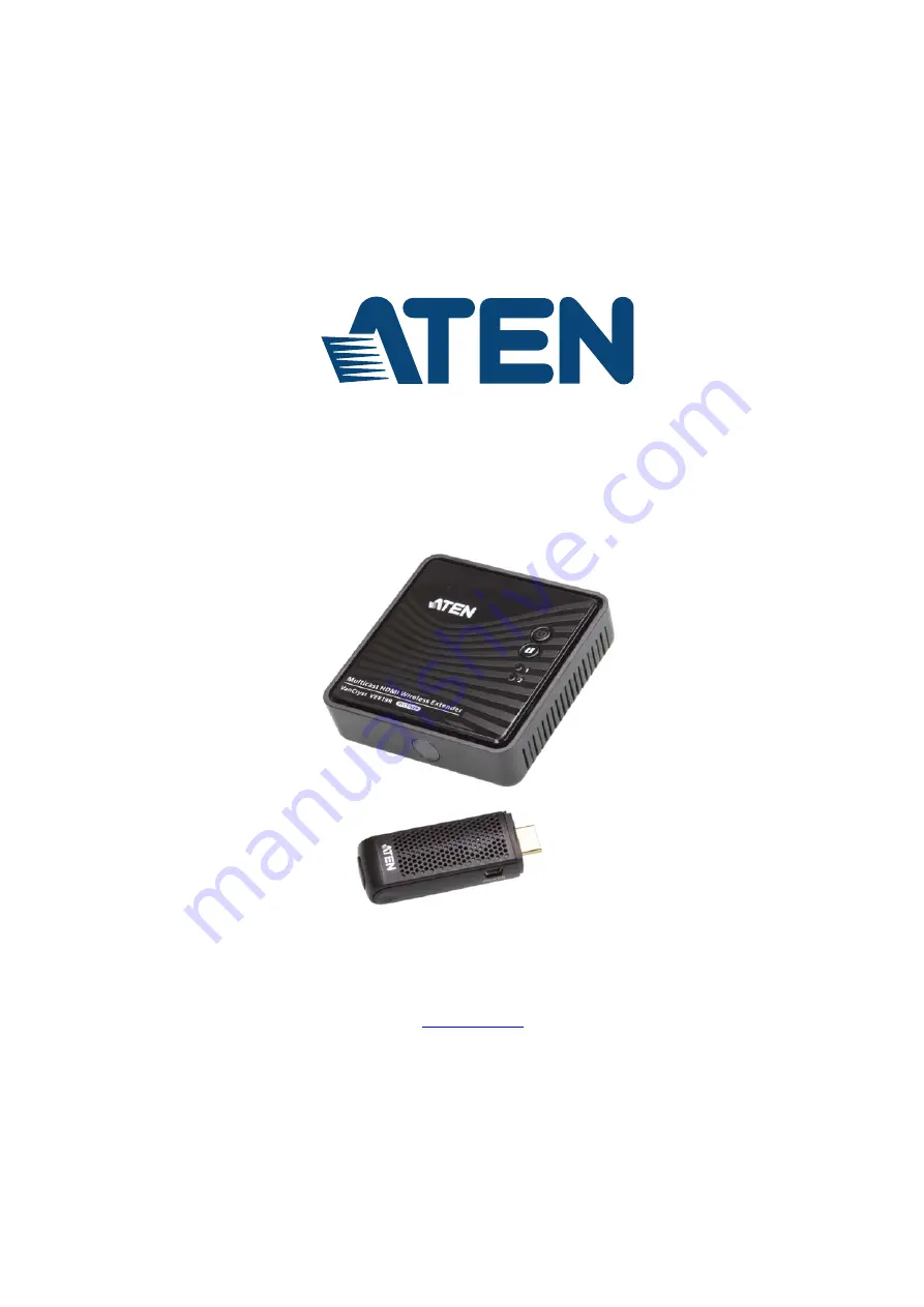
HDMI Dongle Wireless Extender
VE819
User Manual
www.aten.com
Page 1: ...HDMI Dongle Wireless Extender VE819 User Manual www aten com...
Page 2: ...nd on the user is encouraged to try to correct the interference by one or more of the following measures Reorient or relocate the receiving antenna Increase the separation between the equipment and re...
Page 3: ...trum Matters ERM ElectroMagnetic Compatibility EMC standard for radio equipment and services Part 1 Common technical requirements EN 301 489 17 Electromagnetic compatibility and Radio spectrum Matters...
Page 4: ...e following their purchase the buyer and not the manufacturer its distributor or its dealer assumes the entire cost of all necessary servicing repair and any incidental or consequential damages result...
Page 5: ...er Instructions 1 Warranty Card Check to make sure that all the components are present and that nothing got damaged in shipping If you encounter a problem contact your dealer Read this manual thorough...
Page 6: ...erview 1 Features 2 Requirements 3 Sources 3 Components 4 Chapter 2 Hardware Setup Wall Mounting 7 Setup the Wireless HDMI Transmitter and Receiver 9 Chapter 3 Basic Operation Overview 10 Transmitter...
Page 7: ...uces you to the VE819 system Its purpose features and benefits are presented and its front and back panel components are described Chapter 2 Hardware Setup describes how to set up your installation Di...
Page 8: ...ndicates keys you should press For example Enter means to press the Enter key If keys need to be chorded they appear together in the same bracket with a plus sign between them Ctrl Alt 1 Numbered list...
Page 9: ...three extra transmitters can be paired with the receiver allowing users to have four source devices paired concurrently Users can switch between source devices from the receiver side using the IR rem...
Page 10: ...HDI technology Low latency 1 ms WHDI enables delivery of uncompressed high definition digital video over a wireless radio channel connecting any video source to any compatible display device HDCP comp...
Page 11: ...VE819 User Manual 3 Requirements Display A display device with an HDMI Type A input connector Sources A source player with an HDMI Type A output connector...
Page 12: ...ec when establishing the link with the Receiver 2 HDMI Connector Connects the HDMI Transmitter to a laptop or media player s HDMI port 3 Info Pairing Button Press to show information on the screen See...
Page 13: ...Status LED a Blinks quickly when there s no input from a selected source b Blinks slowly when the video format is not recognized c Static blue when the video format is recognized 4 Mini USB Power Jack...
Page 14: ...er 2 Info Press this button to display the OSD on the screen 3 Transmitter No Press this button to switch to another transmitter if more than one Transmitter is being used and within range 4 OK Press...
Page 15: ...ly and drill two holes as instructed 2 Insert anchors into the wall followed by the screws Leave 5 8 of the screw protruding for mounting the Receiver 1 Important safety information regarding the plac...
Page 16: ...Chapter 2 Hardware Setup 8 3 Hang the VE819R by having the bottom panel holes aligned into the screws Slide down into position...
Page 17: ...ess HDMI Transmitter to the USB power adapter If used with a computer connect the Mini USB to USB cable from the transmitter to a USB port on the computer 3 Connect the USB power adapter to the Mini U...
Page 18: ...itter and Receiver the panel LEDs blink to indicate that the two units are establishing a connection This takes around 15 to 20 seconds The LEDs light a steady blue when the connection is established...
Page 19: ...es LED Item Mode Status Description Rx Power LED Rx Status LED OSD Display Standby For power saving mode Static Red off Initial Boot up Warm up It will spend 15 20 seconds for system boot up Blinking...
Page 20: ...o timing setting c If you have more than one transmitter paired to the receiver all devices need to be at least 6 5 feet away from one another If the transmitter and the receiver exist in the same roo...
Page 21: ...the remote control is pressed OSD Main Interface Press the Transmitter No key on the remote control to show the OSD on the HDMI display connected to the receiver Up to four transmitters can be connect...
Page 22: ...w a list of transmitters linked to the receiver Use the Up Down buttons to select the transmitter you want to display on your HDTV HD projector Then press OK and allow 10 12 seconds for the receiver a...
Page 23: ...section allows you to name your transmitters for easy use or reference All individual paired transmitter names can be edited 1 Use the Up Down buttons to select the transmitter you want to modify 2 Th...
Page 24: ...nking While both the Transmitter and Receiver enter pairing mode they will search for each other automatically When they are located the OSD will show the model name of the Transmitter that is being a...
Page 25: ...t Add New Transmitter to search for an available transmitter 4 The OSD will display Searching 5 The Power LED on the receiver will blink PINK when it is in Pairing Mode 6 To exit Searching Mode press...
Page 26: ...ation has been provided Never spill liquid of any kind on the device Unplug the device from the wall outlet before cleaning Do not use liquid or aerosol cleaners Use a damp cloth for cleaning The devi...
Page 27: ...or short out parts resulting in a risk of fire or electrical shock Do not attempt to service the device yourself Refer all servicing to qualified service personnel If the following conditions occur u...
Page 28: ...nd Product model number serial number and date of purchase Your computer configuration including operating system revision level expansion cards and software Any error messages displayed at the time t...
Page 29: ...5 MHz 225 MHz Compliance HDMI 3D HDCP Compatible HDMI 3D HDCP Compatible Max Resolutions Distance Up to 1080p 60Hz 10m Up to 1080p 60Hz 10m Audio Input 1 x HDMI Type A Male Black N A Output N A 1 x HD...
Page 30: ...Appendix 22 Physical Properties Housing Plastic Plastic Weight 26g 128g Dimensions L x W x H 30 x 70 3 x 17 5mm 95 x 95 x 33 3mm Function VE819T VE819R...
Page 31: ...80 59 94 72 809Hz VGA 800x600 60 317 72 188Hz SVGA 1024x768 60 70 069Hz XGA 1280x1024 60 Hz SXGA Mandatory CEA 3D Video Format Timings 1280x720p 50Hz Top and Bottom 1280x720p 50Hz Frame packing 1280x7...
Page 32: ...the distance between the Transmitter and Receiver does not exceed 100 feet Move the Transmitter closer to the Receiver Power LED lights solid Source LED blinking slowly blue Ensure that the video res...
Page 33: ...rom the source device is supported refer to page 23 IR Remote Control cannot control input source device Check where is IR sensor is located on the input source device Make sure that the IR Blaster Ex...
Page 34: ...Appendix 26 Wall Placement Template...
Page 35: ...provide a repair service without charge during the Warranty Period If a product is detective ATEN will at its discretion have the option to 1 repair said product with new or repaired components or 2 r...