background image

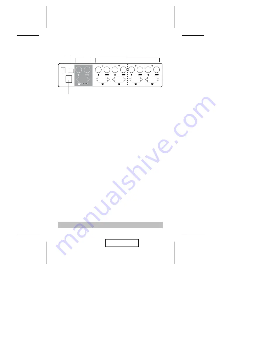
Rear View

1. Power Jack

The CS-114A is designed to be non-powered (external power is not
required - its operation power comes from the computers). In
general, the only time that external power is required is when you
daisy chain it, or if operation becomes erratic because the unit isn’t
obtaining enough power from the computer connections. If you
choose to use external power, the power adapter cable plugs in
here.

2. DIP Switch

Switches 1 and 2 select the Scan Time; Switch 3 selects the Hotkey
Combination; Switch 4 selects the operation type for Last/Next
Mode. See DIP Switch Settings in the Appendix for details.

3. Console Port Section

M

If this is a first station unit, your monitor, keyboard and mouse
plug in here.

M

If this is a daisy chained unit, the cables that link back to a port
on a higher Master View unit plug in here.

4. CPU Port Section

The extender cables that connect the unit’s monitor, keyboard and
mouse ports to the computer’s monitor, keyboard and mouse ports
plug in here.

5. Optional Foot Switch Connector

If you are using an optional foot switch, its cable plugs in here.

- 4 -

1

2

3

4

5

2001 - 01 -03

Summary of Contents for Master View CS-114A

Page 1: ...e vices that connect to them This package contains M 1 Master View CS 114A KVM Switch M 1 Power Adapter M 1 User Manual If anything is damaged or missing contact your dealer Copyright 2000 ATEN Intern...

Page 2: ...e up and eliminates the inconvenience and wasted effort involved in constantly having to move from one computer to the other Features M Supports MS Intellimouse M Mouse Conversion One PS 2 Mouse Contr...

Page 3: ...ugh it is possible to use standard cables to connect the PCs to the CS 114A for optimum signal integrity and to simplify the layout we strongly recommend that you use the following high quality CS Cus...

Page 4: ...sponds to is the currently selected port Depending on the port s status the LED may flash according to a specific pattern see the LED Display table in the Appendix for details 2 Port Selection Switche...

Page 5: ...an Time Switch 3 selects the Hotkey Combination Switch 4 selects the operation type for Last Next Mode See DIP Switch Settings in the Appendix for details 3 Console Port Section M If this is a first s...

Page 6: ...itself 3 Use extender cables see the Hardware Requirements section to connect the keyboard monitor and mouse ports from any available CPU Port 1 4 to the keyboard monitor and mouse ports of the compu...

Page 7: ...prevent damage to your installation due to ground potential difference make sure that all devices on the installation are properly grounded 2 For the First Stage unit plug the power adapter that came...

Page 8: ...ree stage installation are essentially the same as for a two stage installation With a three stage setup however as many as 64 computers can be controlled in a complete installation Note Master View u...

Page 9: ...plug the power adapter cables back in starting with the last station in the chain and working back to the station you originally shut down b After the externally powered units are up turn the computer...

Page 10: ...l RCtrl Hot Key 2 M Selecting the Active Port Since each CPU port is assigned a unique Port ID you can directly access any computer on any level of the installation using a Hotkey combination that spe...

Page 11: ...nit Alt Ctrl Shift 4 2 3 Enter 0r LCtrl RCtrl 4 2 3 Enter Selects the computer connected to Port 3 on a Third Stage unit connected back to Port 2 on a Second Stage unit connected back to Port 4 on the...

Page 12: ...active computer to the next one in the installation Besides being more convenient than Basic Mode the advantage of this method is that the keyboard remains active so you can use the console to carry...

Page 13: ...RShift Next Quick Last Next Mode 4 On LCtrl LCtrl Last RCtrl RCtrl Next 4 Off Disable Appendix Selected LED Display Activity Meaning Off Port is not selected On Steady Port is connected to an active P...

Page 14: ...n Switches Hot Keys Foot Switch Optional LEDs On Line 4 Orange Selected 4 Green Connectors Keyboard 1 x 6 pin mini DIN female PS 2 style Console 4 x 6 pin mini DIN female PS 2 style CPU Ports Mouse 1...

Page 15: ...Use of a Standard Serial Extender Cable with Mouse Port Adapters at Both Ends Because of the wiring and pin assignments you cannot use a Serial to PS 2 adapter at the end that plugs into the CS 114A U...

Page 16: ...has been tested and found to comply with the limits for a Class B computing device pursuant to Subpart J of Part 15 of FCC Rules which are designed to provide reasonable protection against such inter...

Reviews: