background image

63

5. Slide the switch open and closed a couple of times to be sure that it is 

properly aligned and operating smoothly. (See

Opening the Console

page 17, and

Closing the Console

, page 18, for opening and closing 

procedures.)

6. After determining that the switch is properly lined up and operating 

correctly, finish up by fully tightening down the partially tightened front 
attachment screws inserted in step 3.

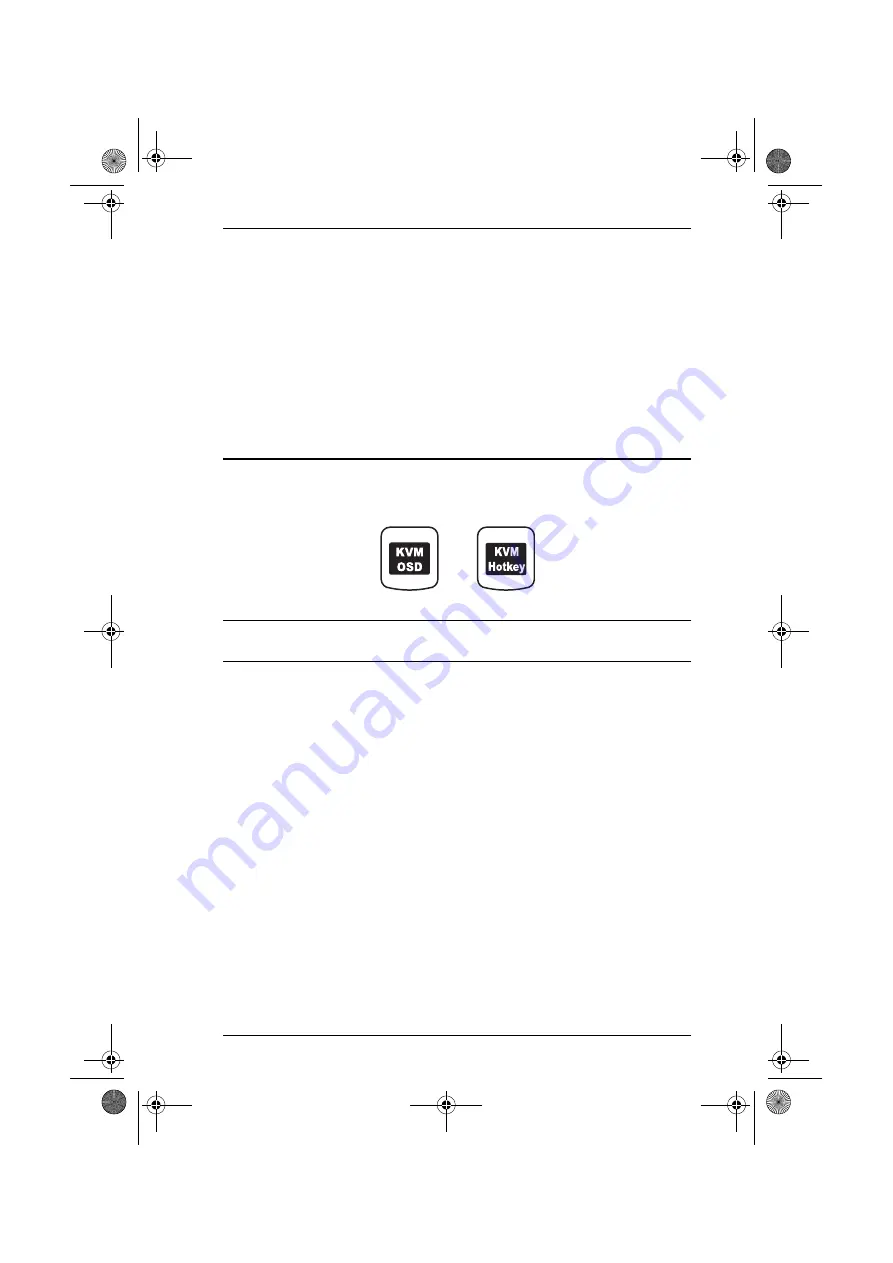
Dedicated Invocation Keys

Two dedicated keys are provided on the keyboard module to make it easy to 
invoke the OSD and Hotkey Mode, as shown in the diagram, below:

Note:

These keys are toggles. Press once to invoke the feature, press again to 
exit.

cl1758.book  Page 63  Thursday, March 30, 2006  3:30 PM

Summary of Contents for CL-1758L

Page 1: ...User Manual CL 1758 cl1758 book Page i Thursday March 30 2006 3 30 PM...

Page 2: ...e reasonable protection against harmful interference when the equipment is operated in a commercial environment This equipment generates uses and can radiate radio frequency energy and if not installe...

Page 3: ...following their purchase the buyer and not the manufacturer its distributor or its dealer assumes the entire cost of all necessary servicing repair and any incidental or consequential damages resultin...

Page 4: ...e a damp cloth for cleaning The device should be operated from the type of power source indicated on the marking label If you are not sure of the type of power available consult your dealer or local p...

Page 5: ...shock Do not attempt to service the device yourself Refer all servicing to qualified service personnel If the following conditions occur unplug the device from the wall outlet and bring it to qualifi...

Page 6: ...fore extending a device from the rack Use caution when pressing the device rail release latches and sliding a device into or out of a rack the slide rails can pinch your fingers After a device is inse...

Page 7: ...nt and in good order If anything is missing or was damaged in shipping contact your dealer Read this manual thoroughly and follow the installation and operation procedures carefully to prevent any dam...

Page 8: ...CL 1758 User Manual viii This Page Intentionally Left Blank cl1758 book Page viii Thursday March 30 2006 3 30 PM...

Page 9: ...ures 3 Hardware Requirements 4 Computers 4 Cables 4 Front View 6 Rear View 8 2 Installation Before You Begin 9 Standard Rack Mounting 9 Single Stage Installation 11 Two Stage Installation 13 Three Sta...

Page 10: ...ve 39 Hotkey Port Access 40 Selecting the Active Port 40 Auto Scanning 41 Invoking Auto Scan Mode 41 Pausing Auto Scan 41 Hotkey Configuration 42 Alternate Hotkey Invocation Keys 42 Alternate OSD Acti...

Page 11: ...Factory Default Settings 58 Clear Login Information 59 Optional Rack Mounting 60 Standard Long 60 Easy Installation 60 Dedicated Invocation Keys 63 Specifications 64 Troubleshooting 65 Limited Warrant...

Page 12: ...CL 1758 User Manual xii This Page Intentionally Left Blank cl1758 book Page xii Thursday March 30 2006 3 30 PM...

Page 13: ...ned operation are provided Chapter 3 Basic Operation explains the fundamental concepts involved in operating the CL 1758 Chapter 4 OSD Operation provides a complete description of the CL 1758 s OSD On...

Page 14: ...press the Enter key If keys need to be chorded they appear together in the same bracket with a plus sign between them Ctrl Alt 1 Numbered lists represent procedures with sequential steps Bullet lists...

Page 15: ...out flip the cover up and you are ready to go to work When finished flip the cover down and slide the KVM module away For further convenience and flexibility the switch also supports an external keyb...

Page 16: ...no incompatibility problems Since the CL 1758 intercepts keyboard input directly it works on multiple operating platforms PC compatible Mac Sun etc There is no better way to save time and money than...

Page 17: ...On Screen Display OSD menus and Hotkeys Auto Scan feature for monitoring user selected computers Hot Pluggable add or remove computers without having to power down the switch Two level password securi...

Page 18: ...e Cables discussion in the next section Cables Only the following ATEN Custom KVM cable sets may be used with these switches Depending on the KVM cable type the switches can link to computers that use...

Page 19: ...with this package 2 For PS 2 port computers we strongly recommend using 2L 5702P cables While the other cables work the keyboard and or mouse will not work if all their connectors keyboard video and...

Page 20: ...CL 1758 User Manual 6 Front View 2 3 6 12 9 10 11 1 13 13 7 8 4 5 cl1758 book Page 6 Thursday March 30 2006 3 30 PM...

Page 21: ...dy under normal conditions but flashes when its port is accessed under Auto Scan Mode see p 37 6 Keyboard 7 Touchpad 8 Power LED Lights BLUE to indicate that the unit is receiving power 9 Rack Mountin...

Page 22: ...onsole The external console s keyboard monitor and mouse cables plug in here 4 KVM Port Section The cables that link to the computers plug in here Note The shape of these 15 pin connectors has been sp...

Page 23: ...gle person Easy Installation kits are available with a separate purchase See Optional Rack Mounting page 60 for optional rack mounting details 1 Important safety information regarding the placement of...

Page 24: ...lides the L brackets into the switch s side mounting brackets from the rear until the bracket flanges contact the rack then using the screws provided with the rack mounting kit screws the L brackets t...

Page 25: ...on p 4 plug the custom SPHD connector into any available KVM Port on the switch 3 At the other end of the cable a For a USB connection plug the USB and video connectors into their respective ports on...

Page 26: ...CL 1758 User Manual 12 Note The CL 1758 initially links to the first port when you turn it on 3 USB Connection 3 PS 2 Connection 1 2 4 cl1758 book Page 12 Thursday March 30 2006 3 30 PM...

Page 27: ...ble KVM Port on the First Stage unit to the Console ports of the Second Stage unit Note Plug the USB connector into the USB port next to the Console SPHD port they are both marked with a similar icon...

Page 28: ...n first After all the Second Stage units have been powered on then the First Stage unit must be powered on next After the Second and First stage units have been powered on the computers can be powered...

Page 29: ...ding to the following sequence 1 For each Third Stage unit plug the power adapter cable into the switch s Power Jack plug the power adapter into an AC source 2 For each Second Stage unit plug the powe...

Page 30: ...CL 1758 User Manual 16 F W UPGRADE NORMAL RECOVER F W UPGRADE NORMAL RECOVER CS 1758 CS 1758 CL 1758 4 cl1758 book Page 16 Thursday March 30 2006 3 30 PM...

Page 31: ...dule out and raise the cover Note As a safety precaution to keep the console from accidentally sliding out the console is locked into the In position Before you can pull the console module out you mus...

Page 32: ...hes on the unit s side rails toward you and push the module in until it stops 2 Release the catches pull the module slightly toward you then push it all the way in Note The reason for the two step pro...

Page 33: ...work Wrong DO NOT lean your body weight on the keyboard module DO NOT place heavy objects on the keyboard module The maximum load bearing capacity of the keyboard module is 30kg Failure to heed the i...

Page 34: ...moves you Right or Up When making an adjustment it increases the value When navigating through the menus this button moves you Left or Down When making an adjustment it decreases the value EXIT When...

Page 35: ...e LCD panel vertically moves the display area up or down Color Temperature Adjusts the color quality of the display You can adjust the warmth value color balance etc The Adjust Color selection has a f...

Page 36: ...h on the parent unit that the cascaded switch is connected to then press the Port Switch on the cascaded switch that corresponds to the device you wish to access OSD OSD On Screen Display provides a m...

Page 37: ...te If the computer s Operating System does not support hot plugging this function may not work properly Hot Plugging Console Ports The unit supports hot plugging of the external keyboard monitor and m...

Page 38: ...nplug the power cords of any computers that have the Keyboard Power On function Otherwise the switches will still receive power from the computers 2 Wait 10 seconds then turn the switch back on If you...

Page 39: ...t Stage unit has a one digit Port ID from 1 8 that corresponds to the KVM Port number that it is connected to A computer attached to a Second Stage unit has a two digit Port ID The first digit represe...

Page 40: ...CL 1758 User Manual 26 This Page Intentionally Left Blank cl1758 book Page 26 Thursday March 30 2006 3 30 PM...

Page 41: ...trator User password system Before the OSD Main Screen comes up a login dialog box appears that asks you to provide your username password If the password function has been set you must provide a vali...

Page 42: ...same position it was in the last time it was closed 3 Only the ports that have been set accessible by the Administrator for the currently logged in User are visible see SET ACCESSIBLE PORTS p 36 for d...

Page 43: ...he screen will scroll To bring the KVM focus to a port Double Click it or move the Highlight Bar to it then press Enter After executing any action you automatically go back to the menu one level above...

Page 44: ...hlight Bar to it then pressing Enter 3 Press Esc to return to the previous menu level F1 GOTO GOTO allows you to switch directly to a port either by keying in the port s Name or its Port ID To use the...

Page 45: ...our choice you return to the OSD Main Screen with the newly formulated List displayed Quick View choices only show up on the Administrator s screen since only he has Quick View setting rights see p 36...

Page 46: ...the Ctrl key combination may conflict with programs running on the computers the default is the Scroll Lock combination PORT ID DISPLAY POSITION Allows you to position where the Port ID appears on th...

Page 47: ...K VIEW Only those Ports which have been set Accessible and have been selected as Quick View Ports see SET QUICK VIEW PORTS p 36 POWERED ON Only those Ports which have been set Accessible and are Power...

Page 48: ...inistrator field or one of the User fields a screen that allows you to key in your username and pass word appears The username and password may be up to 15 characters long and can consist of any combi...

Page 49: ...characters 0 9 and Space 3 When you have finished editing press Enter to have the change take effect To abort the change press Esc RESTORE DEFAULT VALUES This function is used to undo all changes and...

Page 50: ...ion allows the Administrator to define User access to the computers on the installation on a Port by Port basis For each User select the target Port then press Spacebar to cycle through the choices F...

Page 51: ...lar computer either by pressing P or with a Left Click of the mouse To resume scanning press P or Left Click again See Invoking Auto Scan Mode page 41 for further details Note Pressing almost any of t...

Page 52: ...you have to do to reenter the OSD is tap the OSD Hotkey Note 1 When you reenter the OSD after logging out the screen stays blank except for the OSD Main Screen You must input your password before you...

Page 53: ...ock key Num Lock Note There is an alternative key combination to invoke HKM see p 42 When Hotkey Mode is active The Caps Lock and Scroll Lock LEDs flash in succession to indicate so They stop flashing...

Page 54: ...ing the KVM focus to any computer on the installation with a Hotkey combination that specifies the Port ID of the KVM Port that it is connected to The steps involved are 1 Invoke HKM see p 39 2 Key in...

Page 55: ...Scan Mode compliant keystrokes and mouse clicks can be input You must exit Auto Scan Mode in order to regain normal control of the console Pausing Auto Scan While you are in Auto Scan Mode you can pa...

Page 56: ...e two methods To revert back to the original Num Lock Minus method invoke HKM then press and release the H key again Alternate OSD Activation Keys The OSD activation method can be changed from tapping...

Page 57: ...he appropriate Function key see table Note 1 The brackets indicate the keys you should press Simply press the indicated keys do not type the brackets 2 After completing a setting you automatically exi...

Page 58: ...ays Beeper On or Beeper Off for one second then the message disappears and you automatically exit Hotkey Mode Restore Default Settings To reset the CL 1758 to its default hotkey settings do the follow...

Page 59: ...ter keys letters numbers Enter Esc Spacebar etc will resume scanning H Toggles between the default Num Lock and alternate Ctrl F12 Hotkey invocation keys T Toggles between the default Scroll Lock Scro...

Page 60: ...CL 1758 User Manual 46 This Page Intentionally Left Blank cl1758 book Page 46 Thursday March 30 2006 3 30 PM...

Page 61: ...Keyboard Emulation Note When using key combinations press and release the first key Ctrl then press and release the activation key PC Keyboard Mac Keyboard Shift Shift Ctrl Ctrl Ctrl 1 Mute Ctrl 2 V_...

Page 62: ...ation key 2 If you need to go into OK Mode which requires Stop A see Troubleshooting page 65 PC Keyboard Sun Keyboard Ctrl T Stop Ctrl F2 Again Ctrl F3 Props Ctrl F4 Undo Ctrl F5 Front Ctrl F6 Copy Ct...

Page 63: ...KVM switch s firmware The Utility comes as part of a Firmware Upgrade Package that is specific for each device New firmware upgrade packages are posted on our web site as new firmware revisions becom...

Page 64: ...your computer 3 Use the Firmware Upgrade Cable provided with this unit to connect a COM port on your computer to the Firmware Upgrade Port of your switch 4 Shut down all of the computers but not the...

Page 65: ...creen appears Note The screens shown in this section are for reference only The wording and layout of the actual screens put up by the Firmware Upgrade Utility may vary slightly from these examples 2...

Page 66: ...xt to perform the upgrade If you enabled Check Firmware Version the Utility compares the device s firmware level with that of the upgrade files If it finds that the device s version is higher than the...

Page 67: ...Utility installs the upgrade files without checking whether they are a higher level or not As the Upgrade proceeds status messages appear in the Status Messages panel and the progress toward completio...

Page 68: ...procedure was successful Click Finish to close the Firmware Upgrade Utility Upgrade Failed If the Upgrade Succeeded screen doesn t appear it means that the upgrade failed to complete successfully See...

Page 69: ...he following 1 Power off the switch If it is part of a cascade disconnect it from the group 2 Connect the Firmware Upgrade Cable to its Firmware Upgrade Port 3 Slide the Firmware Upgrade Recovery Swit...

Page 70: ...CL 1758 User Manual 56 This Page Intentionally Left Blank cl1758 book Page 56 Thursday March 30 2006 3 30 PM...

Page 71: ...2 62 428 435 6 36 43 25 169 176 44 302 309 63 435 442 7 43 50 26 176 183 45 309 316 64 442 449 8 50 57 27 183 190 46 316 323 65 449 456 9 57 64 28 190 197 47 323 330 66 456 463 10 64 71 29 197 204 48...

Page 72: ...Lock Port ID Display Position Upper Left Corner Port ID Display Duration 3 Seconds Port ID Display Mode The Port Number plus the Port Name Scan Duration 5 Seconds Screen Blanker 0 OFF Logout Timeout 0...

Page 73: ...Restore Default Password at the front center of the switch s main board 3 Power on the switch When you power the switch on the following message appears on the LCD display USERNAME AND PASSWORD INFORM...

Page 74: ...dard Long To install the long bracket standard rack mount kit simply replace the short L brackets on the standard rack mount kit with the long ones and mount the switch according to the instructions g...

Page 75: ...the inside a Screw the front flanges to the rack first b Slide the slide bars toward the rack until the rear flanges make contact with the rack then screw the rear flanges to the rack Rear Attachment...

Page 76: ...he rack only tighten the screws part way 4 Slide the rear attachment sliding brackets along the slide bars until they contact the rear of the switch then use the screws supplied with this package to a...

Page 77: ...witch is properly lined up and operating correctly finish up by fully tightening down the partially tightened front attachment screws inserted in step 3 Dedicated Invocation Keys Two dedicated keys ar...

Page 78: ...1 x Num Lock green 1 x Caps Lock green 1 x Scroll Lock green Switches FW Upgrade Rec 1 x Slide Power 1 x Rocker LCD Adjust 4 Pushbuttons Emulation Keyboard PS 2 Mouse PS 2 Video 15 LCD 1024 x 768 75Hz...

Page 79: ...screen background color is set to black Changing the screen background to a color other than black resolves this problem Limited Warranty IN NO EVENT SHALL THE DIRECT VENDOR S LIABILITY EXCEED THE PR...

Page 80: ...Manual User Manual 66 This Page Intentionally Left Blank cl1758 book Page 66 Thursday March 30 2006 3 30 PM...

Page 81: ...E Edit Port Names 35 F F1 GOTO 30 F2 LIST 31 F3 SET 32 F4 ADM 34 F7 SCAN 37 F8 LOUT 38 FCC Information ii Features 3 Firmware upgrade port 50 Firmware upgrade mode invoking 36 Firmware Upgrade Utility...

Page 82: ...reen Headings 29 Navigation 29 Overview 27 Password 27 OSD Default Settings 58 Overview 1 P Password 27 34 Pause 37 Port ID Display Duration 32 Display Mode 33 Display Position 32 Port ID Numbering 25...

Page 83: ...33 Specifications 64 T Timeout 34 Troubleshooting 65 U Upgrading the Firmware Failed 54 Preparation 50 Recovery 55 Starting 51 Succeeded 54 User Notice iii Username 34 cl1758 book Page 69 Thursday Mar...

Page 84: ...CL 1758 User Manual 70 cl1758 book Page 70 Thursday March 30 2006 3 30 PM...

Reviews: