


5
DIS ---- Indicate WLAN status
ACT ---- It will flash when transmit the data from WLAN to serial
or from serial to WLAN.
PWR ---- Indicate the Power supply
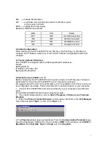
Detail for LINK,DIS Led indicate
LINK
DIS
Status
OFF
OFF
WLAN Connecting
ON
OFF
WLAN Connected
OFF
ON
WLAN Disconnect
ON
ON
Setup Command
2.0 Initial Configuration
When setting up your ATC-2000WF for the first time, the first thing you should do is
configure the IP address. Select one of the initial IP Address configuration methods to
configure
2.1 Factory Default IP Address
ATC-2000WF is configured with the following default IP addresses:
WLAN:
Setting static IP
IP Address 192.168.1.250
Netmask 255.255.255.0
2.2 Serial Console (38400, n, 8, 1)
Before configuring the ATC-2000WF via the serial console, turn off the power and use a
serial cable to connect the ATC-2000WF to your computer
’
s serial port.
We suggest using PComm Terminal Emulator, which is available in CD driver to carry out
the configuration procedure. Firstly install PComm Terminal Emulator on your computer.
1. Connect ATC-2000WF RS-232 serial port directly to your computer
’
s male RS-232
serial
Port with RS-232 DB9 Female Cross Configuration cable
2. From the Windows desktop, click on
Start
#
Programs
#
PComm Lite
#
Terminal
Emulator
.
3. When the
PComm Terminal Emulator
window opens, first click on the
Port Manager
menu item and select
Open
, or click on the
Open
icon.
4. The
Property
window opens automatically. From the
Communication Parameter
page,
select the appropriate COM port for the connection,
COM1
in this example, and
38400
for
Baud Rate
,
8
for
Data Bits
,
None
for
Parity
, and
1
for
Stop Bits
.


