background image

 Installation & Servicing Instructions ATAG E-Series

16

In certain weather conditions condensation may also accumulate on the outside of the
air inlet pipe. Such conditions must be considered and where necessary insulation of the
inlet pipe may be required.
In cold and/or humid weather water vapour may condense on leaving the flue terminal.
The effect of such ‘plumeing’ must be considered.

The terminal must not be located in a place where it is likely to cause a nuisance.
For protection of combustibles, refer to IS 813 section 9.10.1. where the terminal is less
than 2m (6.6ft) above a pavement or platform to which people have access (including) any
balcony or flat roof. The terminal must be protected by a guard of durable material.
A suitable guard is available from the country distributor.

Where a terminal is fitted below a window which is hinged at the top, and
where the hinge axis is horizontal, and the window opens outwards, the
terminal shall be 1m below the bottom of the window opening.

If the boiler is to be located under stairs, a smoke alarm meeting the
requirements of I.S. 409 or equivalent must be fitted.

The flue must be terminated in a place not likely to cause a nuisance.

For horizontal sections, the outlet system should always be fitted on an incline (50 mm/
m) sloping down towards the appliance so that no condensation water is able to
accumulate in the outlet system. The chances of icicles forming on the roof outlet is
minimised by causing the condensation water to run back towards the appliance. In the
case of horizontal outlets the inlet system should be fitted on an incline sloping down
towards the outside to prevent rainwater from coming in.

The appliance produces a white wisp of condensation (plumeing). This wisp of
condensation is harmless, but can be unattractive, particularly in the case of outlets in
outside walls.

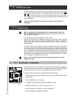
At this time there are 2 different ways of connecting the flue gas/air intake system. The
flue gas duct for the 60/100, 80/125 and 100/150 are push fit connections, see figure 10.
The air intake for the 60/100 is a clamp ring connection.
These two types are not interchangeable.

Cutting the pipe goes as follows:
-

Take out the inner tube by turning it until it releases from its security position;

-

Cut just as much from the air intake part as from the flue gas part;

-

Take off the burrs from the cutting edge to prevent cutting the seals;

-

Click the pipes back together again.

Use special grease to simplify the fitting

When mounting the flue gas system, pay attention to the flow direction. An arrow on the
product points this out. It is not permitted to mount a system upside down and will lead
to complaints.

Dismantlement and shorten pipes

        figure 11

Summary of Contents for E 22C

Page 1: ...3 07 Changes reserved I n s t a l l a t i o n S e r v i c i n g Instructions These instructions to be retained by user Boiler G C No E 22S 41 310 12 E 32S 41 310 13 E 22C 47 310 13 E 32C 47 310 14 CEP...

Page 2: ...sure boiler power of 50 is possible The installation needs to be topped up Operation indication in the first display position of technical read out Water pressure is to high 2 8 bar if HIGH indication...

Page 3: ...theboiler 24 11 1 Central heating system 24 11 2 Hot water supply 24 11 3 Adjustments 25 11 4 Activating factory settings green key function 27 12 Isolating the boiler 28 13 Commissioning 28 13 1 Chec...

Page 4: ...classification On completion of the installation the installer or commissioning engineer must fill out and complete the Benchmark commission section of the boiler log book and hand to customer or end...

Page 5: ...the plug from the wall socket Close the stop cock of the boiler s intake connection Take note of the following when maintenance or adjustments are needed Theboilermustbeabletofunctionduringtheseactivi...

Page 6: ...f the boiler is drained through an internal siphon The boiler is provided with an intelligent control system CMS Control Management System Theboileranticipatestheheatdemandofthecentralheatingsystemort...

Page 7: ...boiler there must be at least 250 mm working space in order to be able to fit a coaxial flue system or a twin supply On the left side of the boiler at least 50 mm and on the right side 10 mm must be...

Page 8: ...215 215 Q pipe lenght of g mm 19 19 215 215 R pipe lenght of c mm 40 40 40 40 S pipe lenght of c and f r k and w mm 50 50 160 160 T back centre of pipe c k and w mm 26 26 26 26 U back centre of pipe...

Page 9: ...es and or to spray clean blow clean the installation before connecting it to the boiler 6 1 Centralheatingsystem Connect the central heating system according to the actual regulations The boiler pipes...

Page 10: ...selected according to the installation resistance and the required flow pump index lines graph 1 As standard the boiler is provided with a water filter in the return pipe of the boiler With this possi...

Page 11: ...asing which can be removed by pullingforwards Theexpansionvesselhasapre chargepressureof1barandacapacity of 12 litres Ifalargercapacityexpansionvesselisneededfortheinstallationastandardexpansion vesse...

Page 12: ...rtaining to plastic underfloor heating pipes 6 4 Gasconnection Theappliancepipeisfittedwithaninternalthread intowhichthetailpieceofthegastap can be screwed United Kingdom Thegassupplymustcomplytothecu...

Page 13: ...ted in the water flow direction Dosingvalve supplied Safetygroup Expansion vessel 6bar potable water blue A dosing valve must be fitted in the cold water pipe The dosing valve ensures that a quantity...

Page 14: ...tlet and air supply installation must comply with the current regulation requirements IG UP 10 and BS 715 Ireland Irish standard is 813 section 9 10 1 Open boiler Room sealed system SS PP SS PP PP SS...

Page 15: ...ribed in this document are solely suited for ATAG central heating boilers of the ATAG boiler range For this purpose the CE Certificate has been supplemented under the Gastec nr 0063BR3405 0063BQ3021 0...

Page 16: ...itted on an incline 50 mm m sloping down towards the appliance so that no condensation water is able to accumulate in the outlet system The chances of icicles forming on the roof outlet is minimised b...

Page 17: ...m the maximum straight length 80mm A in m E22S Maximum straight lenth 80 30 E22C 87 bend resistance length 1 5 45 bend resistance length 0 8 E32S Maximum straight lenth 80 24 E32C 87 bend resistance l...

Page 18: ...xternal hot water cylinders can be connected to the boiler The choice of the cylinder depends on the coil output The coil output must comply with the boiler output The E Series are provided with an in...

Page 19: ...able item No S4477300 The ATAG room thermostat and controls must be connected to their allocated connections Allothertypesormakesofroomthermostatsorcontrolswhichare used must have a Volt free contact...

Page 20: ...e DHW sensor T3 3 way valve Ionisation Ignition Flowswitch Combi Gas valve 24V Return sensor T2 Water pressure sensor P1 Flue gas sensor T5 Optional Flow sensor T1 Fan 24V Pump PWM 230V Control Manage...

Page 21: ...e shown instead of the technical read out To switch over from the Good state to the Technical read out and vice versa Press the STEP key for 5 sec Whenthesystemhasbeenfilledtheautomaticventingprograms...

Page 22: ...d pages per chapter can be retrieved After pressing for 5 seconds it switches from the Good state to technical read out and vice versa Reset key After briefly pressing for unlocking errors ending the...

Page 23: ...op it up to 1 5 to 1 7 bar 15 Close the filling loop 16 Press the STEP button 17 Be sure that the filling loop is closed 18 After the automatic de aeration program A xx is finished the boiler will ret...

Page 24: ...ire adjustment of the burner pressure and air quantity because it is self adjusting and is factory set at the correct value 11 1 Central Heating system Provided there is a heat requirement from the th...

Page 25: ...rameters INFO Information chapter no adjustments possible SERV Service chapter ERRO Error chapter no adjustments possible The content of the chapters is described on the following pages Press briefly...

Page 26: ...ph 20 0 10 0 C fine adjustment heating line day temperature 5 until 5 C 11 0 C fine adjustment heating line night temperature 5 until 5 C 14 7 gradient speed 0 15 15 0 booster after night reduction no...

Page 27: ...ost of the adjustments which are stated in this table are unnecessary when in combination with the ATAG BrainQ thermostat and will be taken care of by the BrainQ itself and do not have to be adjusted...

Page 28: ...antity are unnecessary due to the fact that the boiler operates with a so called zero pressure control Thismeansthecorrectgasquantityiscontrolledbythesuctionoperationofthe fan The fine adjustment whic...

Page 29: ...n the boiler on so that the boiler is alight Press the MODE key for 5 seconds The diplay will show COdE followed by an arbitrary number Select by means of the or the key the code C123 Press the Store...

Page 30: ...de C123 Press the Store key to confirm the code code blinks 1 x Press the MODE key until SERV is shown Press the STEP key once until 1 is shown alternately 1 and OFF will be shown Calibrate the CO2 me...

Page 31: ...ew of the black plastic silencer afterthisturnthetwoclampingrods turnandremovethembypullingthemforward Note the right turning direction red indicator slightly lift the fan unit and remove it towards t...

Page 32: ...with acid free O ring grease to make fitting easier if there is a leak at the siphon cup or tray the complete siphon unit has to be replaced byS4421200 remove the plug from the flue gas sensor if pres...

Page 33: ...onsumption G20 CH DHW at 1013 mbar 15 C m3 h 2 10 2 38 3 05 3 62 2 10 3 05 Electr power consumption max W Electr power consumption stand by W Current V Hz Fuse rating A Degree of protection acc EN 605...

Page 34: ...12 water filter return CH 13 three way valve 14 circulationpump T1 flowsensor T2 returnsensor T3 sensor DHW combi and flow switch ATAG E figure 15 15 flue gas duct 16 combustion air supply 17 type pl...

Page 35: ...A0 Connection terminal ATAG E A1 ATAG BrainQ thermostat RSC A4 Outside sensor ARV12 tra Thermostatic radiator valve BP Automatic by pass Always use a by pass in combination with thermostatic radiator...

Page 36: ...terminal ATAG E A4 Outside sensor ARV12 A9 ATAG MadQ zone coltroller 23BC A11 Connection terminal MadQ wall mounted B Cylinder B3 Cylinder sensor B5 Three way valve cylinder C Direct zone C6 Pump dire...

Page 37: ...eraturehasbeenexceeded ifpresent Theblockwillnotbecancelleduntil the flue gas temperature has lowered to a correct figure Block 81 Thefluegassensorisnotconnectedalthoughitwasconnectedtothecontrol Theb...

Page 38: ...as Appliance Directive 90 396 EEC EN483 1999 EN50165 1997 Efficiency Directive 92 42 EEC EN677 1998 Low Voltage Directive 73 23 EEC EN50165 1997 EN60335 1 1994 EMC Directive 89 336 EEC EN61000 3 2 200...

Page 39: ...20 KIWA Certificate...

Page 40: ...UK ATAG Heating UK Ltd Unit 3 Beaver Trade Park Quarry Lane Chichester West Sussex PO19 8NY Phone 01243 815 770 Fax 01243 839 596 E mail info atagheating co uk Internet www atagheating co uk Ditributo...

Reviews: