5
6
7
4
5
6
7
• Disconnect the electrical connections from the fan (
5
)
• Turn the left (
6
) and right (
7
) clamp bars a quarter turn with a 4mm
Allen key and pull these out in a forward motion. Mind the direction of rotation (red control cams);
• Now lift the complete fan unit (
5
) with the upper tray of the heat exchanger and remove it in a forward-motion
• Turn the unit upside down and remove the burner cassette (
8
) from the ventilator unit
• Check the burner cassette for wear and tear, pollution and any breakages. Clean the burner cassette
with a soft brush and vacuum cleaner
• In the case of breakages, always replace the complete burner cassette (
8
)
The following operations must be performed carefully in relation to the vulnerability of the non return valve.
• After removing the burner cassette (
8
) the non return valve (
12
) becomes visible. Check that the non return valve
entire circumference closes / seals completely. The valve should be able to move freely from fully open to fully
closed. Replace the non return valve if the valve does not seal properly.
• Replace the gasket (
9
) between the burner (
8
) and upper casing (
10
)
• Replace the gasket (
11
) between the upper casing (
10
) and exchanger
!
11
12
8
9
10
32
Summary of Contents for BC100124
Page 1: ...Appliance Technical Guide SERVICE ENGINEER EDITION ...
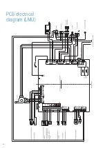
Page 24: ...PCB electrical diagram LMU 24 ...
Page 35: ...Notes 35 ...

