background image

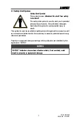
2.1 Safety Alert System

Safety Alert Symbol

This symbol means: 

Attention! Be alert! Your safety

is involved!

The safety alert symbol is used to alert you to potential
personal injury hazards.  Obey all safety messages
that follow this symbol to avoid possible injury or
death.

This symbol is used as an attention-getting device throughout this manual as well
as on decals and labels fixed to the machinery to assist in potential hazard recog-
nition and prevention.

Property or equipment damage warnings in this publication are identified by the
signal word "NOTICE".

2 SAFETY

7

RT-40 US O&M

0404-766   2019-05

“NOTICE” Indicates a hazardous situation which, if not avoided, could
result in property or equipment damage.

NOTICE

Summary of Contents for 0404-766

Page 1: ...RT 40 Version EN Edition 2019 05 Part Number 0404 766 US Valid From Serial No 00100 RT 40 Original Instructions Operation and Maintenance Manual ...

Page 2: ...l in before commissioning the machine Model _________________________ Vehicle Serial Number _________________________ Year of Manufacture _________________________ Commissioned on _________________________ Dealer ...

Page 3: ...9 Machine Description Controls 35 Operation 53 Transportation 63 Maintenance 71 California Proposition 65 93 1 Page The operator must read and understand all of the instructions in this manual before operating the machine RT 40 US O M 0404 766 2019 05 ...

Page 4: ...e machine The operator must read understand and obey the instructions in both this and the AEM safety manual for skid steer and compact track loaders prior to operating or performing maintenance or service on the machine Should you need clarification or further explanation of the topics in this manual please contact your dealer immediately for assistance Information describing special equipment or...

Page 5: ...r to register the machine in their name This will ensure that they will be notified in the event of a safety related bulletin affecting their machine 1 6 Contacting the Manufacturer If you have questions relating to ownership including but not limited to accident reporting current owner updates product applications and safety standards and regulations compliance product modifications transfer of o...

Page 6: ...quires Ultra Low Sulfur Diesel ULSD fuel to operate properly There are special considerations regarding the use and handling of ultra low sulfur diesel fuel Information on these topics can be found on the following pages 18 19 section 2 10 Fuel Handling Precautions and 34 section 3 11 Fluid Specifications The RT 40 is also equipped with self diagnostic features common to modern diesel engines Info...

Page 7: ... 2 8 Stability 17 2 9 Transport of Persons 17 2 10 Fire Prevention 18 2 11 Crush Burn Avoidance 19 2 12 Placing Into Operation 20 2 13 Starting the Machine 20 2 14 Jobsite Safety 21 2 15 Parking the Machine 22 2 16 Towing Retrieving 22 2 17 Transporting 23 2 18 Maintenance 24 2 19 Battery 26 2 20 Hydraulic Lines Hoses 27 Page 5 2 SAFETY RT 40 US O M 0404 766 2019 05 ...

Page 8: ...6 RT 40 US O M 0404 766 2019 05 This Page Intentionally Left Blank ...

Page 9: ... injury or death This symbol is used as an attention getting device throughout this manual as well as on decals and labels fixed to the machinery to assist in potential hazard recog nition and prevention Property or equipment damage warnings in this publication are identified by the signal word NOTICE 2 SAFETY 7 RT 40 US O M 0404 766 2019 05 NOTICE Indicates a hazardous situation which if not avoi...

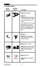
Page 10: ...njected into skin must be surgically removed within a few hours by a doctor familiar with this type of injury or gangrene will result Hazard Fall Avoidance Use the provided access system when entering or exiting the machine Hazard Rollover Ejection Avoidance Carry loads low keep heaviest end of machine uphill at all times while operating on inclines Hazard Burn Scald Avoidance Allow to cool before...

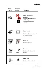
Page 11: ...arks away No Smoking Read and understand all manuals Hazard Corrosive Avoidance Read and understand the operator s manual Hazard Fall Avoidance No Riders Hazard Burn Avoidance Do not touch hot surfaces Hazard Crush Avoidance Fasten seat belt 9 2 SAFETY RT 40 US O M 0404 766 2019 05 F ll H d F ll H d ...

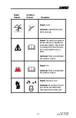
Page 12: ...azard Entanglement Avoidance Stop machine and remove key before servicing Hazard Fall Avoidance Do not use the bucket or attachment as a work platform Hazard Crush Avoidance Keep clear of moving machine Hazard Crush Avoidance Keep clear of lift arms and attachments St l f l d d b k t 10 2 SAFETY RT 40 US O M 0404 766 2019 05 ...

Page 13: ...sonal injury hazards Obey all safe ty messages that follow this sym bol to avoid possible injury or death Avoidance Read and understand the operator s manual Hazard Fire Avoidance Read and understand the operator s manual Hazard Explosion Burn Avoidance No smoking Keep all open flames and sparks away Stop engine before adding fuel 2030 417 11 2 SAFETY RT 40 US O M 0404 766 2019 05 ...

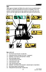
Page 14: ...e 4 Read operator s manual inside cab enclosure 5 Skin oil injection hazard 6 Clean undercarriages notice 7 Crush hazard run over 8 Crush hazard lift arm brace 9 Crush hazard lift arms 10 Fire hazard read operator s manual inside cab enclosure 11 Tie down locations 12 2 SAFETY RT 40 US O M 0404 766 2019 05 2030 416 2030 415 2030 417 2030 425 2030 553 2030 427 2030 426 Carry loads low Ca arry loads...

Page 15: ...t 13 Emergency Exit rear window front door if equipped 14 Explosion burn hazard read operator s manual 15 Skin oil injection hazard 16 Crush hazard lift arm brace 17 Crush Hazard Lift arms 18 Crush hazard run over 19 Clean undercarriages notice 20 Explosion burn hazard read operator s manual engine compartment 21 Burn hazard engine compartment 22 Entanglement hazard engine compartment 13 2 SAFETY ...

Page 16: ...feet to ensure your safety Ensure the access system step and handholds are clean prior to entering or exiting the machine Do not use any method of operation inspection or maintenance that may impair safety This machine is only to be used when properly equipped for the task to be performed and when properly inspected and maintained to ensure safe operation The manufacturer s instructions regarding ...

Page 17: ...and any other equipment necessary to ensure your safety and the safety of others around you as you work 2 6 Hazard Zone The hazard zone encompasses the area around the machine in which persons may be injured by movements of the machine its attachments or by falling loads during operation Do not position yourself or allow anyone else within this hazard zone during machine operation Keep a safe dist...

Page 18: ...arize him herself with the local jobsite conditions and immediately remedy any fault that may compromise safety use the machine in accordance with the appropriate local jobsite organization system to ensure safe coordination with other machines vehicles and people on the jobsite Investigate any jobsite prior to operation to determine whether any special haz ards exist Take necessary measures to el...

Page 19: ...t end of the machine facing uphill when working on an incline When operating on any surface other than firm and level ground use extra caution Decrease work speeds limit load size and make any other necessary adjustments to maximize your safety and that of others in the work area Note The parking brake which is activated by pressing the switch item 3 section 4 1 automatically when the engine is tu...

Page 20: ...efective parts Oil leaks can easily lead to a fire NEVER use bare hands to check for hydraulic leaks Pressurized fluid oil can penetrate skin and cause gangrene If injection occurs seek medical attention immediately Do not use any starting aids containing ether to start diesel engines with pre heat systems Use of starting aids of this nature can cause an EXPLOSION Familiarize yourself with the loc...

Page 21: ...aised or open hinged items hoods doors engine enclosure panels and similar Never align holes with your fingers when working on the machine Instead use a suitable mandrel Keep yourself and all objects that could be drawn into the fan at a safe distance while the engine is running The entire cooling system is hot and under pressure when it is at or near operating temperature Avoid touching parts tha...

Page 22: ...e machine and warn any persons standing nearby that the machine will be placed into operation Prior to placing the machine into operation adjust the driver s seat mirrors if equipped and ventilation system settings if equipped so you can work in comfort and safety 2 13 Starting the Machine Before starting check all indicator lamps and instruments to make certain they are working properly Start the...

Page 23: ...at an adequate distance from overhead electrical lines When working in the vicinity of overhead electrical lines do not come close to the lines with the machine Injury or death may result If possible have the current turned off or line re routed prior to beginning work In the event electrical current jumps from a line to the machine follow these rules do not perform any movements with the machine ...

Page 24: ...ng the Machine Always observe the correct procedure as described in the operating instructions The machine should be towed only in exceptional cases for example to bring the machine away from an endangered place for repair Towing equipment such as chains cables etc must be of the correct capacity and must use both of the multi purpose tie down locations on the rear of the chassis Pull the chains t...

Page 25: ...essure by making sure all operating levers and switches are in their neutral positions Remove the ignition key Secure the door windows and hood on the machine Secure the machine and any other items against slipping with chains ropes of the proper capacity Before departure investigate the route to be taken especially in regard to limits for width height and weight Pay close attention when driving u...

Page 26: ...d Be sure all protective devices including guards and shields are properly installed and functioning correctly before beginning any service task If a guard or shield must be removed to perform the maintenance work use extra caution Always use the appropriate tools for the work to be performed Tools should be in good condition and you should understand how to use them properly before performing any...

Page 27: ...to the product in question Ensure that fuels lubricants and coolants as well as replaced parts are disposed of in an environmentally proper manner Proceed carefully when working with hot lubricants coolants and fuels danger of burns and scalding Relieve Hydraulic System Pressure Prior to attempting any hydraulic maintenance or repair relieve hydraulic system pressure by performing the following 1 ...

Page 28: ...f they were not designed for that purpose If working at significant height use a safety harness of the proper style and capacity to prevent falls Keep all grips steps platforms ladders etc free of snow ice water mud sludge oil etc 2 19 Battery corrosive Use caution wear face shield safety gloves and any other appropriate safety equipment when working near or with the battery The battery contains a...

Page 29: ...nded operating times will further reduce hose service life Hoses and hose lines must be replaced if any of the following criteria are encountered during inspections damage to the outer hose up to the insert for example worn spots cuts and tears embrittlement of the outer layer formation of cracks in the hose material deformation when under pressure without pressure or when bending which differ fro...

Page 30: ...28 RT 40 US O M 0404 766 2019 05 This Page Intentionally Left Blank ...

Page 31: ...ine 32 3 4 Electrical 32 3 5 Undercarriage 32 3 6 Transmission 33 3 7 Auxiliary Hydraulics 33 3 8 Ground Pressure 33 3 9 Operating Specifications 33 3 10 Service Refill Capacities 33 3 11 Fluid Specifications 34 3 12 Dimensions and Weights 34 RT 40 US O M 0404 766 2019 05 ...

Page 32: ...30 RT 40 US O M 0404 766 2019 05 This Page Intentionally Left Blank ...
Page 33: ...ction 4 6 3 Operator Enclosure R O P S F O P S approved 4 Diesel Fuel fill location right side engine compartment see section 2 10 5 Hydraulic Oil fill location right side engine compartment 6 Hood engine cover 7 Engine 8 Drive Motor and Sprocket 9 Undercarriage 10 Quick Attach 11 Bucket 12 Lift Arm 13 Product PIN Plate left side of cab enclosure 3 8 5 4 6 7 10 9 11 12 13 1 2 ...

Page 34: ...0 all directions engine Intermittent 30 all directions engine Cooling Water antifreeze for all year operation Operating Voltage 12 V Battery 12V 525 CCA Alternator 12V 60A Starter 12V Starting Aid Glow Plugs automatic Lighting System Cab mounted work lights Type Suspended rubber track w screw tension Travel Speed max 7 1 mph 11 4 kph Drive Motors fixed disp radial piston motor Track length on grou...

Page 35: ...xial piston pump Displacement 1 71 in 28 0 cc revolution Relief Pressure 5500 psi 37 921 kPa Make Rexroth Design Gear Displacement 1 16 in 19 cc revolution Relief pressure 3000 psi 20 684 kPa Flow 13 3 gpm 50 4 lpm 2 700 RPM At operating weight 3 5 psi 24 1 kPa Tipping load 2660 lb 1207 kg Operating capacity 50 tip load 1330 lb 603 3 kg Operating capacity 35 tip load 931 lb 422 3 kg Fuel tank 13 g...

Page 36: ...b 75 5 in 1918 mm Ground Clearance 10 8 in 274 3 mm Weight operating 4175 lb 1894 kg Weight shipping w o bucket 3767 lb 1709 kg 40 40 28 9 20 17 8 0 6 7 20 4 4 40 15 6 60 26 7 80 37 8 100 48 9 C 120 F 10W 30 15W 40 SAE 30 Recommended Viscosity Grades Ambient temperature 30 F 115 F Specifications Designation Specification standard Fuel Diesel Fuel Ultra Low Sulfur Diesel ASTM S 15 Engine Oil Engine...

Page 37: ...lements 37 4 2 Symbols 38 4 3 Controls 40 4 4 Throttle 40 4 5 Operator Seat 41 4 6 Electric Attachment Control 41 4 7 Auxiliary Hydraulics 42 4 8 Operator Interface 43 4 9 Emergency Exits 51 4 10 Attachment Compatibility 52 RT 40 US O M 0404 766 2019 05 ...

Page 38: ...36 RT 40 US O M 0404 766 2019 05 This Page Intentionally Left Blank ...

Page 39: ...able mounting solutions for personal items within the cab Consult your local dealer for more information 1 2 3 4 7 6 8 9 The RT 40 is equipped with self diag nostic features common to modern diesel engines Should an alarm mes sage be displayed or red amber lights illuminate on the operator interface during normal operation shut the machine down immediately in a safe location Consult your dealer to...

Page 40: ... US O M 0404 766 2019 05 4 2 Symbols Symbol Description Parking Brake Battery Engine Speed Fast Engine Speed Slow Windshield Wiper do not use in dry conditions Engine Pre Heat Oil Pressure Engine Coolant Temperature Hydraulic Oil Temperature ...

Page 41: ... 4 MACHINE DESCRIPTION CONTROLS RT 40 US O M 0404 766 2019 05 Symbol Description Engine RPM Work Lights Ultra Low Sulfur Diesel Fuel Only Hydraulic Oil Only Beacon Light Tie Down Auxiliary Hydraulics Fan ...

Page 42: ...tick base Pull back quickly to disengage the float function 4 3 2 Drive Control The drive joystick controls the direction and speed of the machine The illustration above shows the relationship between joystick movement and resulting machine motion 4 4 Throttle The throttle twist knob is located on the right side of the dash panel when seated in the machine The throttle controls engine rpm Twist th...

Page 43: ...ol Attachments for the RT 40 are controlled by pressing various buttons on the joy sticks or switches in the cab Most attachments are controlled hydraulically but some require both hydraulic and electrical inputs The upper 4 buttons on the left joystick 4 6 1 can send up to 20 amps combined of electrical current to pins B C D G of the receptacle on the lift arms 4 6 1 Attachments requiring electri...

Page 44: ...y hydraulics can provide either variable or continuous flow depending on the requirements of the attachment being utilized To engage variable auxiliary hydraulic flow activate the roller style switch on the top of the right joystick labeled 2 in figure 4 7 2 To engage continuous auxiliary hydraulic flow activate the 3 position switch on the dash panel labeled 3 in figure 4 7 3 Moving the variable ...

Page 45: ...is turned to the on position the operator interface powers up to display gauge screen 1 as pictured below This screen displays engine RPM fuel level and engine coolant temperature The selection bar visible on this screen allows the operator to Access the brightness contrast adjustment screen Access subsequent gauge screens up or down arrows Access the main menu lower right icon To access these sub...

Page 46: ...ess the buttons beneath the arrows to access the various gauge screens as needed To reset Trip Hours 1 Press the rightmost button beneath the screen to access the main menu 2 Press the button beneath the down arrow icon to select System Setup then press the button beneath the check mark rightmost button to confirm 3 From the System Setup menu select Trip Reset similarly to step 2 4 Select yes from...

Page 47: ... and down arrows to select a sub menu Once you have made your selection press the button beneath the check mark to confirm Note Any time the open door icon lower left corner above is present you may press the button beneath it to return to Gauge Screen 1 Basic Setup Menu This screen allows you to enter the following sub menus to change display parameters Time Date Language Units Main Menu Basic Se...

Page 48: ...u to access various sub menus relating to diagnostics System Info This screen will display system information relating to the machine s operating hardware and software Diagnostics System Info HW ser 500566630025 SW ver 7010735v005 SYS ver 10106196v140 Node 33 System Info Fault Log Device List Quick Data ...

Page 49: ...ed flashing lights will illuminate accompanied by a pop up message listing the current fault Lights will continue to flash until acknowledged and will remain illuminated until the fault is cleared Press the button located beneath the open door icon to clear the pop up and return to the previous screen Press the buttons below the arrow keys to toggle between multiple faults Press the button beneath...

Page 50: ...o select data signals for display on the above Quick Data screen Highlight selections with the buttons beneath the up and down arrows then confirm by pressing the button beneath the check mark icon Once selected return to the Quick Data display screen by pressing the button beneath the open door icon To view toggle through the selected signals with the buttons beneath the arrow keys as described a...

Page 51: ...you do and would like to return to the default settings follow the directions under Reset Defaults in this section System Setup This screen allows you to access sub menus relating to the system setup It is not recommended to alter settings in the CAN Display and PIN Setup sub menus Screen Setup Parameters Number Of Screens Select Screens System Setup Reset Defaults CAN Display PIN Setup Trip Reset...

Page 52: ...ec tion with the buttons below the up and down arrows then confirm by pressing the button below the check mark Trip Reset This screen allows you to reset the Trip Hours Toggle to your desired selection with the buttons below the up and down arrows then confirm by pressing the but ton below the check mark Reset Defaults No Yes Trip Reset No Yes Are you sure ...

Page 53: ...in an emergency Operator Escape Door Exit Firmly grasp the triangular tag attached to the win dow molding on the front door Pull on the tag forcefully to remove the window molding then push or kick the window out to escape fig 4 9 2 Operator Escape Rear Window Exit Firmly grasp the triangular tag attached to the window molding on the rear window Pull on the tag forcefully to remove the window mold...

Page 54: ...ectrical attachment receptacle If electrical actuation is required and not require electrical input in excess of the 20 amp max supplied by the machine section 4 6 Have matching auxiliary hydraulic quick couplers and components that are designed to operate within the range of pressures and flows supplied by the CTL auxiliary hydraulic system chapter 3 Not detrimentally impact machine stability dur...

Page 55: ...ng Procedure 56 5 4 Surface Preservation 57 5 5 Filling the Bucket 57 5 6 Grading 58 5 7 Leveling 58 5 8 Loading 59 5 9 Fastening Attachments 59 5 10 Unfastening Attachments 60 5 11 Operation on Inclines 61 5 12 Shut Down Procedure 61 5 13 Lift Arm Brace 62 Page RT 40 US O M 0404 766 2019 05 ...

Page 56: ...54 RT 40 US O M 0404 766 2019 05 This Page Intentionally Left Blank ...
Page 57: ...assis 10 The seat belt and lap bar restraint are in good working order 11 All safety signs are in place and legible on the machine 12 All control devices are present in good operating condition and are not damaged in any way 13 The rear view mirror if equipped is adjusted for proper viewing 14 All guards shields and access panels are in place and secure 15 The backup alarm is audible when the driv...

Page 58: ... While this occurs the pre heat operation light will illuminate 5 Once the pre heat operation light goes out turn the ignition key to the right to start the engine 6 With the exhaust adequately vented bring the engine and hydraulic oil up to operating temperature Low oil temperatures can cause the control system to respond sluggishly 7 Set the throttle to desired rpm for operation Note The parking...

Page 59: ...f make gradual turns see item A If space is limited turn gradually by moving back and forth until facing the desired direction see item B 5 5 Filling The Bucket Steps see illustration section 5 1 1 Lower the lift arms until they rest on the frame 2 Tilt the bucket slowly forward until the cutting edge engages the ground 3 Drive the machine forward until the bucket is full of material 4 Curl the bu...

Page 60: ...ft arms as you tilt the bucket slowly forward to evenly spread the material out over the ground 2 Once the load is released tilt the bucket forward to an angle 45 or less to the ground 3 Lower the lift arms until the cutting edge rests on the ground 4 Engage the float function which allows the lift arms to follow the contours of the ground with only their own weight acting as down pressure and bac...

Page 61: ...s fig 5 10 1 2 With the lift arms fully lowered drive the machine to the attachment and hook the top edge of the quick attach under the upper lip of the attachment 3 Curl the quick attach slowly upward by moving the lift arm control joystick to the left until the attachment is properly mated with the quick attach mechanism Curl enough to lift the attachment off of the ground 4 Once the attachment ...

Page 62: ... the outside of the machine to unlock the attachment 3 Lay the attachment gently onto the ground by moving the lift arm control joystick slowly to the right 4 Once the attachment is in contact with the ground move the lift arm control joystick gently to the right until the quick attach is clear of the attachment 5 Back the machine away from the attachment 5 10 1 5 10 3 5 10 2 RT 40 US O M 0404 766...

Page 63: ...nts and vandals 3 Lower the lift arms until they rest on the frame stops 4 Reduce engine RPM to a low idle see section 2 10 when refueling 5 Turn the ignition key counterclockwise to stop the engine remove key 6 Remove the seat belt and raise the lap bar 7 Open the door if equipped and exit the machine using 3 points of contact as described in the starting procedure in this section Even with these...

Page 64: ...e onto the top side of the cylinder ram and install the retaining pins to secure it there then stand clear 5 Slowly lower the lift arms until they come to rest on the brace To remove 1 Raise the lift arms until they are clear of the brace 2 Have an assistant withdraw the retaining pins and remove the brace from the cylinder then stand clear 3 Lower the lift arms to the lower stop 4 Have the assist...

Page 65: ...ANSPORTATION 63 6 1 Transporting 65 6 2 Tie Down Points 66 6 3 Towing Retrieving 66 6 4 Lift Points 68 6 5 Overhead Lifting Procedure 68 6 6 Loading Unloading Procedure 70 Page RT 40 US O M 0404 766 2019 05 ...

Page 66: ...64 RT 40 US O M 0404 766 2019 05 This Page Intentionally Left Blank ...
Page 67: ...he machine over the distance and terrain that will be covered 2 Secure the machine to the transport vehicle bed with heavy chains rated for use with a machine of this nature size and weight 3 Attach the chains to the machine at four points one on each corner of the machine and secure to suitable locations on the transport vehicle Items A and B fig 6 1 1 and 6 1 2 Tighten as needed to eliminate pos...

Page 68: ...s A fig 6 1 1 chains must extend forward a minimum of 23 from points A on either side of the machine with a minimum chain length of 43 4 The chains may only extend forward up to 35 from points A max chain length of 50 8 Rear Tie Down Points see figure 6 2 1 When securing the machine at the rear using tie down points B fig 6 1 2 chains must extend rearward a minimum of 36 8 from points B on either ...

Page 69: ...6 TRANSPORTATION 67 RT 40 US O M 0404 766 2019 05 6 2 1 FRONT 6 3 1 TOP VIEW SIDE VIEW A B REAR Note If an attachment causes machine weight to exceed 6150 lb 2790 kg the attach ment must also be secured ...

Page 70: ...ny damage resulting from improper use This risk is borne solely by the user 6 5 Overhead Lifting Procedure The RT 40 is equipped with lift points that allow it to be lifted from above for transportation purposes To lift the RT 40 1 Shut the machine down in accordance with the shut down procedure in section 5 12 of this manual remove any attachments from the machine 2 Attach the lifting apparatus s...

Page 71: ...ift vertically as shown Chains straps must remain vertical throughout the lifting operation fig 6 5 1 The spreader beam pictured above is a general representation only It s pur pose is to illustrate that the lifting chains must remain vertical during lifting Weight of machine being lifted must not exceed 4500 lb 2041 kg 4500 lb 2041 Kg 6 5 1 ...

Page 72: ...hen to stop and park the machine Lower the lift arms and turn off the engine 8 Before securing the machine relieve all residual pressure by making sure the operating levers and the auxiliary hydraulic switch are in their neutral positions Remove the ignition key 9 Secure the door windows and hood on the machine 10 Secure the machine and any other items to the transport vehicle with chains or ropes...

Page 73: ... Belt 79 7 10 Water Separator 80 7 11 Fuel Filter Change 80 7 12 General Undercarriage 81 7 13 Track Tension Check 81 7 14 Track Tension Adjustment 82 7 15 Drive Sprocket Rollers 83 7 16 Air Cleaner 84 7 17 Radiator Oil Cooler Cleaning 86 7 18 Engine Coolant Change 86 7 19 Chassis Cleaning 87 7 20 Oil Separator Element 88 7 21 Electrical System 89 7 22 Storage 90 7 23 Lifting Jacking Procedure 92 ...

Page 74: ...72 RT 40 US O M 0404 766 2019 05 This Page Intentionally Left Blank ...

Page 75: ...ld follow the procedures in this manual and take any necessary precautions to ensure his her safety Wear appropriate per sonal protection equipment for all tasks 7 2 Care and cleaning Cleaning the machine Do not use aggressive detergents to clean the machine We recommend using commercially available cleaning agents for passenger cars Linings insulating materials etc should not be exposed directly ...

Page 76: ...splay for water in fuel fault message drain as required 80 13 Lubricate all grease points 75 14 Inspect clean the coolers and engine compartment chassis 86 87 15 Inspect clean undercarriages as needed 81 16 Inspect replace missing damaged safety signs 12 13 Daily Page 1 Inspect drive sprocket rollers replace as needed 83 2 Replace engine oil and filter initial break in service only 77 Page 1 Repla...

Page 77: ... side of the machine with the exception of items D Lubricate all points daily prior to operation A Lower Bucket Cylinder Pivot B Upper Bucket Cylinder Pivot C Front Lift Cylinder Pivot D Door Hinges if equipped E Lift Arm Pivot F Rear Lift Cylinder Pivot G Rear Axle Pivot H Front Axle Pivot I Quick Attach Pivot J Quick Attach Pins H F I A B C RT 40 US O M 0404 766 2019 05 E G J D ...

Page 78: ...position 5 Remove the dipstick once again and inspect the end for oil on the level indicator 6 Oil should be present on the dipstick up to but not over the upper full level indicator If the level is correct reinstall the dipstick and then reverse step 2 to complete the procedure fig 7 5 2 7 If the level is low add the proper grade and viscosity engine oil and re check as necessary until the proper...

Page 79: ...engine to access the oil drain plug 3 Remove the oil drain plug item 1 fig 7 6 1 from the bottom of the pan 4 Drain the oil into a suitable catch container 5 Remove the engine oil filter item 2 fig 7 6 2 6 Apply fresh oil to the new oil filter seal and install the new filter fig 7 6 2 7 Tighten filter according to the specifications on the filter label or box 8 Reinstall the oil drain plug as foun...

Page 80: ...ug item 1 as shown fig 7 7 1 4 Drain the used oil into a suitable catch container 5 Dispose of the oil according to mandates 6 Reverse step 3 above to reinstall the drain plug and access panel Tighten to secure 7 Open the hydraulic oil fill cap item 4 fig 7 7 3 then refill the hydraulic system with Mobile DTE 10 Excel Series 46 Hydraulic Oil Note Observe the hydraulic oil level sight gauge item 5 ...

Page 81: ...be removed for maintenance or service always inspect it for damage prior to re installation If none is found it may be reused if damaged replace it 7 9 Accessory Belt s The accessory belt on the RT 40 should be visually inspected daily Replace if damaged To inspect 1 Shut the machine down according to the procedure in section 5 12 allow the machine to cool 2 Open the hood at the rear of the machin...

Page 82: ...lter s Change The fuel filters should be changed every 500 service hours or as needed A plugged fuel filter can cause loss of engine power rough running or no start To change the filter 1 Shut the machine down according to the procedure in section 5 12 allow the machine to cool before performing this procedure 2 Open the hood to access the fuel filters 3 Clean the outside of the filters items 2 3 ...

Page 83: ...ear and damage Operation on sand turf or other finished surfaces may require less frequent cleaning but daily inspection is still advised 7 13 Track Tension Check Proper track tension is important for optimum performance and maximum track life Operating with tracks that are too loose can cause them to misfeed possibly causing damage During the first 50 hours of operation the tracks will break in a...

Page 84: ...he track tension device 3 Once the jam nut is loose turn the lower nut B to increase tension until within specification figure 7 14 2 4 Turn the lower nut the opposite direction to loosen the track 5 Once proper tension is achieved retighten the jam nut A on the tensioner Note If the track tensioner is stiff it may be helpful to apply a penetrating lubri cant onto the threads prior to adjusting te...

Page 85: ...te on steel pins 2 limiting wear to the inside of the rollers As they wear the rollers become thinner but will continue to function and perform as long as they are rotating At 50 hour intervals shut the machine down as described in section 5 12 and visually inspect rollers Replace any that show signs of cracking or wear through Drive sprocket removal and roller pin replacement should be performed ...

Page 86: ...d to access the air cleaner housing 2 Open the latches 1 on the air cleaner housing to release the cover pull to remove 3 Immediately vacuum the inside of the housing to remove loose dirt 4 Once any dirt particles have been removed slowly remove the primary element 2 taking care not to disturb dirt that may be caked around the filter seal 5 Again vacuum the canister 6 Carefully remove the secondar...

Page 87: ...er in the absence of this message you may remove the cover steps 1 2 section 7 16 at 250 hour intervals to inspect them in place If heavily soiled service the air cleaner section 7 16 DO NOT clean air filter elements while the engine warranty is in effect During the warranty period replace air filter elements instead of cleaning them Heavy duty air filter manufacturers will not warrant the air fil...

Page 88: ...the machine down as described in section 5 12 and allow it to cool thoroughly then open the hood to access the cooler assembly 2 Open the drain valve item 1 fig 7 18 1 and drain the old coolant into a suitable catch container Dispose according to mandates 3 Close the drain valve and tighten then add coolant with SCA additive see engine manual into the radiator through the fill neck until full 4 Wa...

Page 89: ...out through the lower openings 5 Re secure the acess panels then close and secure the hood to complete the cleaning procedure Coolant and machine components can be HOT Allow the machine to cool thoroughly prior to performing maintenance or service to avoid the possibility of burns If any safety signs are found to be damaged or missing after cleaning contact your dealer for a replacement immediatel...

Page 90: ...sen and lower the clamp securing the hose to the bottom of the oil sepa rator housing then disconnect the hose fig 7 20 3 7 20 4 5 Using a short angled 1 1 16 or met ric equivalent wrench remove the lower cap fig 7 20 5 7 20 6 6 Remove and replace the filter element and o ring seal on the lower cap fig 7 20 6 7 20 7 7 Reverse steps 1 5 of this procedure to restore the machine to operating con diti...

Page 91: ...UX B WIF SENSOR LIGHTS AUX G ECM PWR MAIN PWR C MAIN PWR A PILOT ENABLE MAIN PWR B 5 5 15 5 FUEL PUMP DIODE PILOT CONTROL PILOT ENABLE DISPLAY CONTINUOUS FLOW BACKUP ALARM WIPER HVAC AUX LOADER LIGHTS IGNITION PWR OUTLET AIR RIDE SEAT BEACON DOME LIGHT GLOW PLUG MAIN 1 MAIN 2 MAIN PWR C MAIN PWR B MAIN PWR A AUX D STARTER 1 2 5 37 HP TRACK LOADER CHASSIS HARNESS 2014 301 RELAYS USED 7071 853 2014 ...

Page 92: ... Park the machine in a dry place that provides protection from the elements Drain and refill the cooling system with 50 50 pre mixed antifreeze water Replace engine oil and filter chapter 7 Replace hydraulic oil and filters chapter 7 Jack the machine and rest the chassis on suitable mechanical supports to remove weight from the torsion axles and suspend the tracks off of the ground Apply protectiv...

Page 93: ... ground Install fully charged battery Remove exhaust outlet cover Perform pre operation safety checklist in chapter 5 of this manual Perform starting procedure chapter 5 Let engine run while observing engine monitoring systems gauge screens lights Look for anything out of the ordinary Should the engine coolant temperature exceed the normal range or should oil pressure read abnormally low or hydrau...

Page 94: ...g sure they are positioned beneath the torsion axles only and spaced in such a manner that the machine will be stable when its weight rests solely on the supports 7 Once the supports are in place slowly lower the machine onto them and then remove the jack Repeat steps 4 7 at the rear of the machine should both ends of the machine need to be off of the ground for service Lift the machine straight u...

Page 95: ... of machines operated within its borders must provide a clear warning to customers regarding exposure to substances commonly associated with the machine that are recognized by the state as harmful The manufacturer provides the following information WARNING Cancer and Reproductive Harm www P65Warnings ca gov 0404 841 ...

Reviews:

Related manuals for 0404-766