


ASUS TROOPER B150 D3
1-27
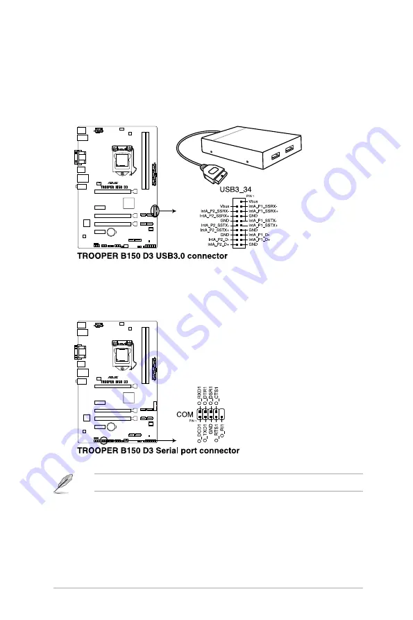
9.
Serial port connector (10-1 pin COM)
This connector is for a serial (COM) port. Connect the serial port module cable to this
connector, then install the module to a slot opening at the back of the system chassis.
The COM module is purchased separately.
8.
USB 3.0 connector (20-1 pin USB3_34)
These connectors allow you to connect a USB 3.0 module for additional USB 3.0 front
or rear panel ports. With an installed USB 3.0 module, you can enjoy all the benefits of
USB 3.0 including faster data transfer speeds of up to 5Gbps, faster charging time for
USB-chargeable devices, optimized power efficiency and backward compatibility with
USB 2.0.
Summary of Contents for Trooper B150 D3
Page 1: ...Motherboard TROOPER B150 D3 ...
Page 11: ...ASUS TROOPER B150 D3 1 3 1 2 3 Motherboard layout ...
Page 14: ...1 6 Chapter 1 Product Introduction 1 3 1 Installing the CPU 1 2 3 A B A B C 4 5 ...
Page 22: ...1 14 Chapter 1 Product Introduction 2 3 To remove a DIMM B A A 1 4 3 Installing a DIMM 1 ...
Page 38: ...1 30 Chapter 1 Product Introduction ...


