background image

ST555 

2

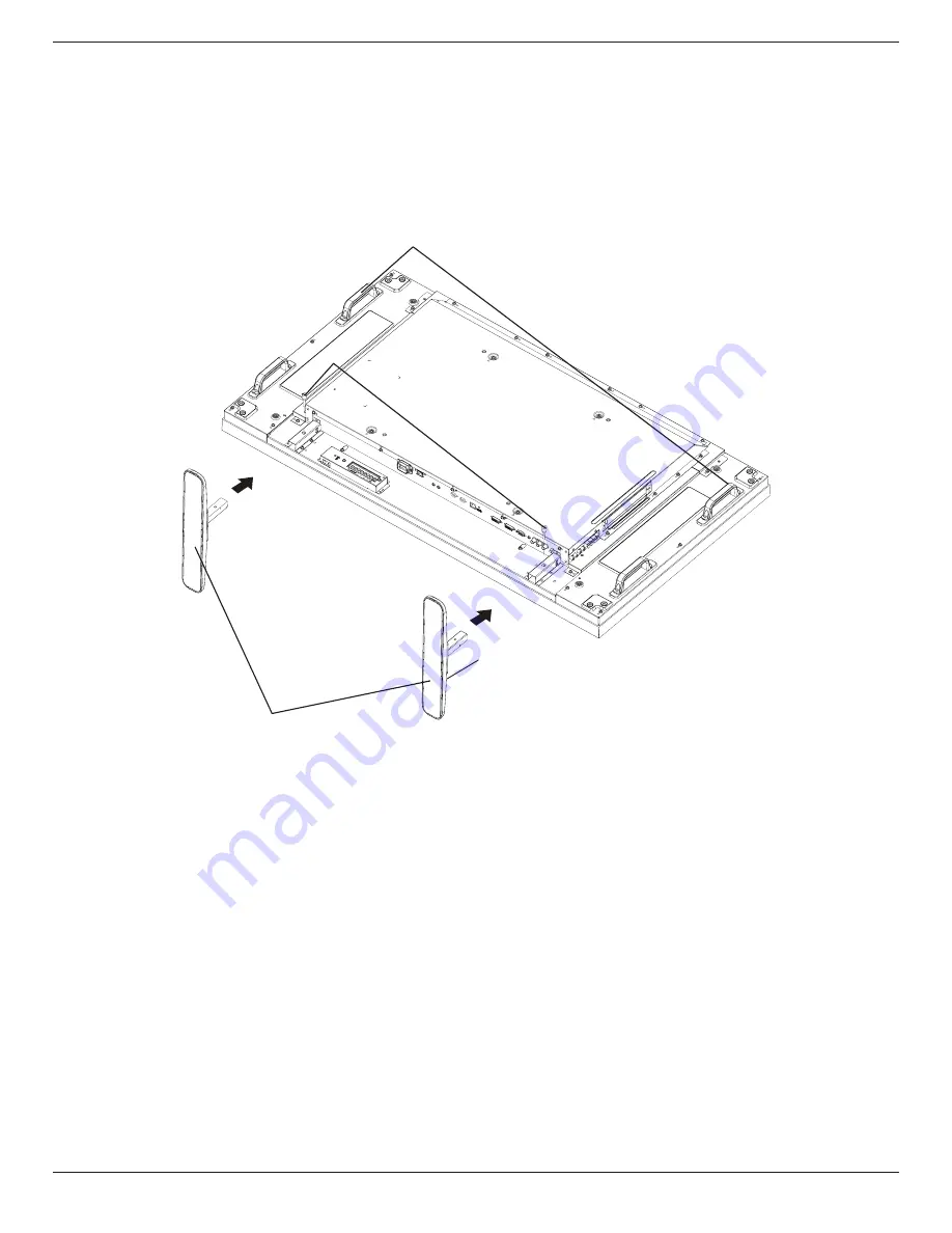
1.4.  Installing and Removing Table Stands (optional)

To install table stands:

1.  Ensure your display is powered off.
2.  Spread a protective sheet on a flat surface.
3.  Grab the carrying handles and place the display face-down on the protective sheet. 
4.  After inserting the stand in the guide block, tighten the screws on both sides of the display.
NOTE:    The longer side of the stand should face the front of the display.

Carrying handle

Thumbscrews

Table stand

Logoer portions face to front

To remove table stands:

1.  Power off the display.
2.  Spread a protective sheet on a flat surface.
3.  Grab the carrying handles and place the display face-down on the protective sheet. 
4.  Remove screws using a screwdriver and place them in a safe place for reuse.

Summary of Contents for ST555

Page 1: ...ST555 User Manual English ...

Page 2: ...ock the ventilation holes on the cabinet Keep the display dry To avoid electric shock do not expose it to rain or excessive moisture If turning off the display by detaching the power cable wait for 6 seconds before re attaching the power cable for normal operation To avoid the risk of shock or permanent damage to the set do not expose the display to rain or excessive moisture When positioning the ...

Page 3: ...tionTechnology Equipment EN55024 2010 Immunity requirement of InformationTechnology Equipment EN61000 3 2 2006 A1 2009 A2 2009 Limits for Harmonic Current Emission EN61000 3 3 2008 Limitation ofVoltage Fluctuation and Flicker following provisions of directives applicable 2006 95 EC LowVoltage Directive 2004 108 EC EMC Directive 2009 125 EC ErP Energy related Product Directive EC No 1275 2008 and 6...

Page 4: ...ndards PN 93 T 42107 and PN 89 E 06251 Electric Magnetic and Electronmagnetic Fields EMF 1 We manufacture and sell many products targeted at consumers which like any electronic apparatus in general have the ability to emit and receive electromagnetic signals 2 One of our leading Business Principles is to take all necessary health and safety measures for our products to comply with all applicable l...

Page 5: ...ould not be greater than 5A NOTE The severed plug must be destroyed to avoid a possible shock hazard should it be inserted into a 13A socket elsewhere How to connect a plug The wires in the mains lead are coloured in accordance with the following code BLUE NEUTRAL N BROWN LIVE L GREEN YELLOW EARTH E 1 The GREEN YELLOW wire must be connected to the terminal in the plug which is marked with the lett...

Page 6: ...mation on recycling contact www eia org Consumer Education Initiative Waste Electrical and Electronie Equipment WEEE Attention users in European Union private households This marking on the product or on its packaging illustrates that under European Directive 2002 96 EG governing used electrical and electronic appliances this product may not be disposed of with normal household waste You are respo...

Page 7: ...1 1 3 Installation Notes 1 1 4 Installing and RemovingTable Stands optional 2 1 5 Mounting on a Wall 3 1 5 1 VESA Grid 3 1 5 2 This display is also able mounted in landscape and portrait positions 3 1 6 Mounting in Portrait Position 4 2 Parts and Functions 5 2 1 Control Panel 5 2 2 Input OutputTerminals 6 2 3 Remote Control 7 2 3 1 General functions 7 2 3 2 Inserting the batteries in the remote co...

Page 8: ...D SUB to D SUB Cable NOTES For all other regions apply a power cord that conforms to the AC voltage of the power socket and has been approved by and complies with the safety regulations of the particular country You might like to save the package box and packing material for shipping the display 1 3 Installation Notes Due to the high power consumption always use the plug exclusively designed for t...

Page 9: ...e stand in the guide block tighten the screws on both sides of the display NOTE The longer side of the stand should face the front of the display Carrying handle Thumbscrews Table stand Logoer portions face to front To remove table stands 1 Power off the display 2 Spread a protective sheet on a flat surface 3 Grab the carrying handles and place the display face down on the protective sheet 4 Remov...

Page 10: ...y does not cover damage caused by improper installation 4 For the wall mounting kit use M6 mounting screws having a length 10 mm longer than the thickness of the mounting bracket and tighten them securely 1 5 1 VESA Grid ST555 400 H x 400 V mm Caution To prevent the display from falling For wall or ceiling installation we recommend installing the display with metal brackets which are commercially ...

Page 11: ...ST555 4 1 6 Mounting in Portrait Position This display can be installed in portrait position 1 Remove the table stand if attached 2 Rotate 90 degrees anticlockwise 90 90 ...

Page 12: ...Control functions To enable or disable the keyboard control lock press both and buttons and hold down continuously for more than 3 three seconds 9 Remote control sensor and power status indicator Receives command signals from the remote control Indicates the operating status of the display without OPS Lights green when the display is turned on Lights red when the display is in standby mode Lights ...

Page 13: ...rol center 8 HDMI IN HDMI video audio input 9 DisplayPort DisplayPort video input 10 DVI IN DVI D video input 2 2 Input OutputTerminals 1 2 3 4 6 7 8 10 11 12 13 14 15 5 9 17 18 19 20 16 11 DVI OUT VGA OUT DVI orVGA video output 12 VGA IN D Sub VGA video input 13 VGA AUDIO IN Audio input forVGA source 3 5mm stereo phone 14 COMPONENT IN BNC ComponentYPbPr video source input 15 Y CVBS Video source i...

Page 14: ...u 8 AUTO ADJUST button Press to run the Auto Adjust function NOTE This button is functional forVGA input only 9 MUTE button Press to turn the mute function on off 10 VIDEO SOURCE button Press to toggleVideo Source Menu Press or button to select one of the video sources among Displayport DVI D VGA HDMI Component Video or Card OPS Press SET button to confirm and exit 11 AUDIO SOURCE button Press to ...

Page 15: ...ot intend to use the remote control for a long period remove the batteries 2 3 3 Handling the remote control Do not subject to strong shock Do not allow water or other liquid to splash the remote control If the remote control gets wet wipe it dry immediately Avoid exposure to heat and steam Other than to install the batteries do not open the remote control 2 3 4 Operating range of the remote contr...

Page 16: ... 3 1 Connecting External Equipment DVD VCR VCD 3 1 1 Using COMPONENT video input DVD VCR VCD AUDIO IN COMPONENT IN YPbPr COMPONENT Out YPbPr Audio Out R L 3 1 2 UsingVideo Source input DVD VCR VCD AUDIO IN Y CVBS IN Y CVBS Out Audio Out R L ...

Page 17: ...ST555 10 3 1 3 Using HDMI video input DVD VCR VCD HDMI Out HDMI IN 3 2 Connecting a PC 3 2 1 UsingVGA input PC VGA IN VGA AUDIO IN VGA Out D Sub 15 pin Audio Out AUDIO IN R L ...

Page 18: ...ST555 11 3 2 2 Using DVI input PC VGA AUDIO IN DVI Out Audio Out AUDIO IN R L DVI IN 3 2 3 Using HDMI input PC HDMI Out HDMI IN ...

Page 19: ...ng DisplayPort input PC DisplayPort Out DisplayPort IN 3 3 Connecting Audio Equipment 3 3 1 Connecting external speakers External speakers 3 3 2 Connecting an external audio device Stereo Amplifier AUDIO OUT R L Audio In ...

Page 20: ... IR OUT 3 4 2 IR PassThrough Control To control aVideo Wall set up by multiple displays use the IR Sensor Cable and the IR Cable to achieve the function IR Sensor Cable IR input port of the DVD player Display IR IN IR OUT IR Cable Remote control of DVD player DVD Player 1 Connect the IR Sensor Cable to the IR IN port of the display 2 Connect with the IR Cable from the IR OUT port of the display to...

Page 21: ...plays 5x5 can be used in a daisy chain configuration 3 5 1 Display control connection Connect the RS232C OUT connector of DISPLAY 1 to the RS232C IN connector of DISPLAY 2 PC DISPLAY 2 DISPLAY 1 RS 232C IN RS 232C RS 232C OUT RS 232C IN 3 5 2 Digital video connection Connect the DVI OUT VGA OUT connector of DISPLAY 1 to the DVI IN connector of DISPLAY 2 PC DVI IN DVI DVI VGA OUT DVI IN DISPLAY 2 D...

Page 22: ...OUT VGA IN 3 5 4 IR daisy chain Connection Connect IR Sensor Cable to DISPLAY 1 and connect the RS232C OUT connector of DISPLAY 1 to the RS232C IN connector of DISPLAY 2 DISPLAY 2 DISPLAY 1 RS 232C OUT IR Sensor Cable POWER SMART VIDEO SOURCE PIP INPUT ON OFF CHANGE BRIGHTNESS CONTRAST DISPLAY AUTO ADJUST MUTE VOL UP VOL DOWN EXIT MENU SET AUDIO SOURCE RS 232C IN IR IN ...

Page 23: ...NOISE REDUCTION FILM MODE PICTURE RESET PICTURE RETURN EXIT MENU 50 50 70 50 BRIGHTNESS Adjust the overall image brightness by changing the intensity of the LCD panel s backlight CONTRAST Adjust to sharpen the picture quality The black portions of the picture become richer in darkness and the white become brighter SHARPNESS Adjust to improve the image detail BLACK LEVEL Adjust to change the image ...

Page 24: ...ess the button to move the image to the right or to move the image to the left V POSITION Press the button to move the image up or to move the image down CLOCK Adjust the width of the image NOTE This item is functional forVGA input only CLOCK PHASE Adjust to improve the focus clarity and stability of the image NOTE This item is functional forVGA input only ZOOM MODE The pictures you receive may be...

Page 25: ...ITION SUB INPUT PIP RESET PIP RETURN EXIT MENU SMALL MAIN AUDIO 100 0 VIDEO OFF PIP MODE Select the PIP Picture in Picture mode The options are OFF PIP POP SBS ASPECT SBS FULL PIP SIZE Select the size of the sub picture in the PIP Picture in Picture mode The options are SMALL MIDDLE LARGE PIP AUDIO Select the audio source in the PIP Picture in Picture mode MAIN AUDIO Select audio from the main pic...

Page 26: ...em number 1 7 and then press SET button to mark it the item number EXIT MENU SEL RETURN EXIT MENU SCHEDULE TODAY 1 2 3 4 5 7 6 2011 08 04 THU 20 19 55 ON EVERY DAY OFF INPUT WED SAT MON THU SUN TUE FRI EVERY WEEK 4 1 2 3 3 Press or button to select the schedule 1 POWER ON schedule Press or button to set the hour and minute for the display to turn on 2 POWER OFF schedule Press or button to set the ...

Page 27: ...ATION OSD Set the period of time the information OSD displayed on the upper right corner of the screen The information OSD will display when input signal is changed The information OSD will remain on the screen with OFF selection The options are OFF 3 SEC 10 SEC MONITOR INFORMATION Displays the information about your display including MODEL NAME and SERIAL MONITOR ID Set the ID number for controll...

Page 28: ...tions are displayed in sync with the secondary audio CC4 Information related to the secondary audio is displayed without sync TT1 TT2 TT3 TT4 Four types of information not related to the displayed images are displayed For example news and weather forecast NOTE Check with each supplier of your video software and external video devices in advance whether they are compliant with EIA 608 A If their vi...

Page 29: ...depending on their source device DVI MODE Used for DVI D signal Select DVI PC when the source device is a PC Select DVI HD when the source device is a video device HDMI SIGNAL Used for HDMI signal Select LIMITED when displaying the signal that uses 16 to 235 levels of 256 levels for each R G and B Select FULL when displaying the signal that uses all 256 levels from level 0 to 255 PIP 1 2 3 EXIT ME...

Page 30: ...values ADVANCED OPTION RESET Reset all settings in the ADVANCED OPTION menu to factory preset values 1 Press SET button to enter the submenu 2 Press or button to select YES and then press SET button to do the reset EXIT MENU SET SEL RETURN SET EXIT MENU ADVANCED OPTION RESET NO YES FACTORY RESET Reset all the settings in the OSD menus of PICTURE SCREEN AUDIO PIP CONFIGURATION1 CONFIGURATION2 CONFI...

Page 31: ...27 MHz HDTV Resolution Standard Resolution Active Resolution Refresh Rate Pixel Rate Aspect Ratio Stand for Mode H Pixels V Lines 720p 1280 720 50 Hz 74 25 MHz 16 9 Normally DVB Mode 60 Hz 1080i 1920 1080 25 Hz 74 25 MHz 16 9 Normally ATSC Mode 30 Hz 1080p 1920 1080 50 Hz 148 5 MHz 16 9 Normally ATSC Mode 60 Hz The PC text quality is optimum in HD 1080 mode 1920 x 1080 60Hz Your PC display screen ...

Page 32: ...t free cloth If the surface becomes dirty soak a soft lint free cloth in a mild detergent solution Wring the cloth to remove excess liquid Wipe the surface of the display to remove dirt Then use a dry cloth of the same type to dry Do not scratch or hit the surface of the panel with fingers or hard objects of any kind Do not use volatile substances such as insert sprays solvents and thinners Cabine...

Page 33: ... underscan 3 If the image exceeds the screen size Scan Mode may need to be set to Underscan Use the Zoom mode or Custom zoom function in the Screen menu to fine tune display geometry and time frequency parameter Can hear sound but no picture Improperly connected source signal cable Make sure that both video inputs and sound inputs are correctly connected Can see picture but no sound is heard 1 Imp...

Page 34: ...put D Sub Jack x 1 15 pin Analog RGB 0 7V p p 75Ω H CS V TTL 2 2kΩ SOG 1V p p 75Ω MAX 720p 1080p 1920 x 1080 60 Hz WUXGA DVI I DVI D VGA Output DVI I Jack x 1 29 pin Digital RGB TMDS Video Analog RGB 0 7V p p 75Ω H CS V TTL 2 2kΩ SOG 1V p p 75Ω MAX 720p 1080p 1920 x 1080 60 Hz WUXGA Component Input BNC Jack x 3 Y 1V p p 75Ω Pb 0 7V p p 75Ω Pr 0 7V p p 75Ω MAX 480i 576i 480p 576p 720p 1080i 1080p V...

Page 35: ...20 60 C Humidity Operational 20 80 RH No condensation Storage 5 95 RH No condensation Altitude Operational 0 3 000 m Storage Shipment 0 9 000 m Internal Speaker Item Specifications Type 1 Way 1 Speaker Input 10 W RMS Impedance 8Ω Output Sound Pressure 82 dB W M Frequency Response 160 Hz 13 KHz ...

Reviews: