background image

ASUS RS520-E6/ERS8

1-7

1.7 

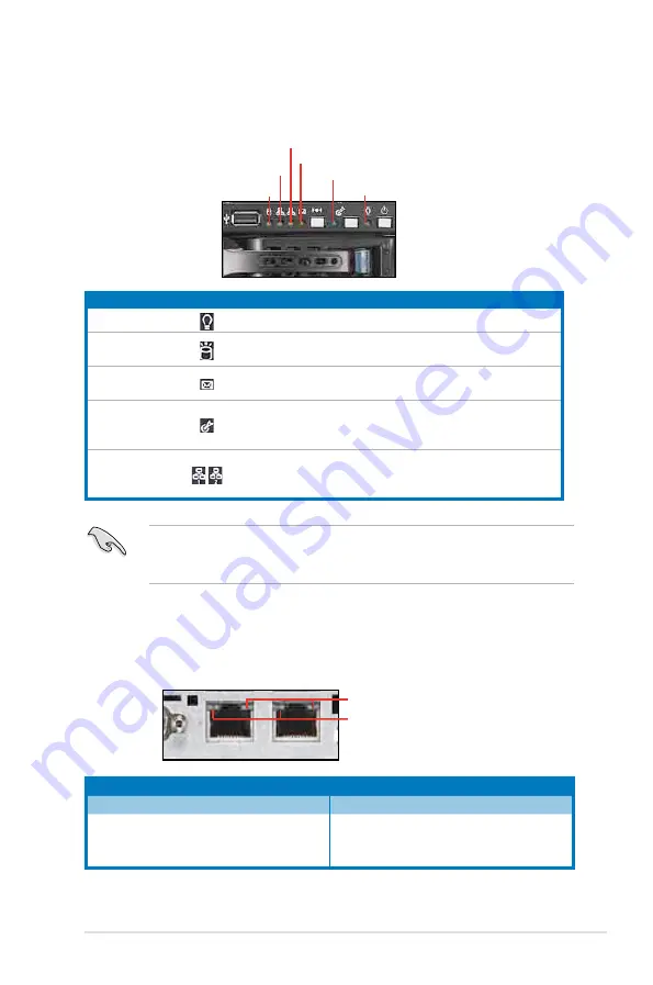
LED information

1.7.1 

Front panel LEDs

1.7.2 

LAN (RJ-45) LEDs

LED

Icon

Display status Description

Power LED

ON

System power ON

HDD Access LED

OFF 

Blinking

No activity 

Read/write data into the HDD

Message LED

OFF 

Blinking

System is normal; no incoming event


ASWM indicates a HW monitor event

Location LED

OFF 

ON

Normal status 

Location switch is pressed 

(Press the location switch again to turn off)

LAN LEDs


OFF 

Blinking


ON

No LAN connection 

LAN is transmitting or receiving data 

LAN connection is present

ACT/LINK LED

SPEED LED

Status

Description

Status

Description

OFF

No link

OFF

10 Mbps connection

GREEN

Linked

ORANGE

100 Mbps connection

BLINKING

Data activity

GREEN

1 Gbps connection

Message LED

LAN2 LED

HDD Access LED

LAN1 LED

Power LED

Location LED

SPEED LED
ACT/LINK LED

The Message LED functions only when you install the optional ASMB4-iKVM 

server management board. Contact the local sales or dealer for detailed 

information on purchasing the server management board.

Summary of Contents for RS500A-X6 PS4

Page 1: ...2U Rackmount Server RS520 E6 ERS8 User Guide ...

Page 2: ...tion of business and the like even if ASUS has been advised of the possibility of such damages arising from any defect or error in this manual or product Specifications and information contained in this manual ae furnished for informational use only and are subject to change at any time without notice and should not be construed as a commitment by ASUS ASUS assumes no responsibility or liability f...

Page 3: ... Hardware setup 2 1 Chassis cover 2 2 2 2 Central Processing Unit CPU 2 3 2 2 1 Installing the CPU 2 3 2 2 2 Installing the CPU heatsink and airduct 2 6 2 3 System memory 2 7 2 3 1 Overview 2 7 2 3 2 Memory configurations 2 8 2 3 3 Installing a DIMM 2 9 2 3 4 Removing a DIMM 2 9 2 4 Hard disk drives 2 10 2 5 Expansion cards 2 12 2 5 1 Installing an expansion card to the riser card bracket 2 12 2 5...

Page 4: ... 3 Internal connectors 4 9 Chapter 5 BIOS setup 5 1 Managing and updating your BIOS 5 2 5 1 1 AFUDOS utility 5 2 5 1 2 ASUS CrashFree BIOS 3 utility 5 4 5 2 BIOS setup program 5 5 5 2 1 BIOS menu screen 5 6 5 2 2 Menu bar 5 6 5 2 3 Navigation keys 5 6 5 2 4 Menu items 5 7 5 2 5 Sub menu items 5 7 5 2 6 Configuration fields 5 7 5 2 7 Pop up window 5 7 5 2 8 Scroll bar 5 7 5 2 9 General help 5 7 5 3...

Page 5: ...hapter 6 RAID configuration 6 1 Setting up RAID 6 2 6 1 1 RAID definitions 6 2 6 1 2 Installing hard disk drives 6 2 6 1 3 RAID controller selection 6 3 6 1 4 Setting the RAID item in BIOS 6 3 6 2 LSI Software RAID Configuration Utility 6 4 6 2 1 Creating a RAID set 6 5 6 2 2 Adding or viewing a RAID configuration 6 11 6 2 3 Initializing the virtual drives 6 12 6 2 4 Rebuilding failed drives 6 16 ...

Page 6: ... Chapter 7 Driver installation 7 1 RAID driver installation 7 2 7 1 1 Creating a RAID driver disk 7 2 7 1 2 Installing the RAID controller driver 7 5 7 2 Intel chipset device installation 7 12 7 3 LAN driver installation 7 14 7 4 VGA driver installation 7 17 7 5 Management applications and utilities installation 7 19 7 5 1 Running the support DVD 7 19 7 5 2 Drivers menu 7 19 7 5 3 Utilities menu 7...

Page 7: ...r is encouraged to try to correct the interference by one or more of the following measures Reorient or relocate the receiving antenna Increase the separation between the equipment and receiver Connect the equipment to an outlet on a circuit different from that to which the receiver is connected Consult the dealer or an experienced radio TV technician for help Canadian Department of Communications...

Page 8: ... server carefully read all the manuals included with the server package Before using the server ensure all cables are correctly connected and the power cables are not damaged If any damage is detected contact your dealer as soon as possible To avoid short circuits keep paper clips screws and staples away from connectors slots sockets and circuitry Avoid dust humidity and temperature extremes Place...

Page 9: ...ttings and connector locations 5 Chapter 5 BIOS information This chapter tells how to change system settings through the BIOS Setup menus and describes the BIOS parameters 6 Chapter 6 RAID configuration This chapter tells how to change system settings through the BIOS Setup menus Detailed descriptions of the BIOS parameters are also provided 7 Chapter 7 Driver installation This chapter provides in...

Page 10: ...mphasize a word or a phrase Key Keys enclosed in the less than and greater than sign means that you must press the enclosed key Example Enter means that you must press the Enter or Return key Key1 Key2 Key3 If you must press two or more keys simultaneously the key names are linked with a plus sign Example Ctrl Alt D Command Means that you must type the command exactly as shown then supply the requ...

Page 11: ...1 ASUS RS520 E6 ERS8 This chapter describes the general features of the chassis kit It includes sections on front panel and rear panel specifications Chapter 1 Product introduction ...

Page 12: ...x PCI Riser Card PCIE8X3 R20A Accessories 2 x CPU Heatsinks varies by territories 1 x RS520 E6 ERS8 User s Guide 1 x ASWM 2 0 User s Guide 1 x RS520 E6 ERS8 Support CD including ASWM 1 x Bag of Screws 2 x AC Power Cable 1 x Semi ball Bearing Rail Kit Optional Items 1 x CA eTrust Anti virus Software CD 1 x Slim Type Optical Device 1 x Second 770W Redundant Power Supply Module 1 x PIKE 1064E 1078 1 ...

Page 13: ...um up to 96GB RDIMM Maximum up to 48GB UDIMM Memory Type DDR3 1333 1066 800 Reg DIMM Unbuffered DIMM with ECC Memory Size 512MB 1GB 2GB 4GB and 8GB Expansion Slots Total PCI PCI X PCI E Slots 3 Slot Type 2 x PCI E x8 slots x8 link Full Height Full Length 1 x PCI E x4 slot x4 link Full Height Half Length Additional Slot 1 x PIKE slot with PCI E G1 x4 link Storage SATA Controller Intel ICH10R 6 x SA...

Page 14: ...ver 2003 R2 Enterprise 32 64 bit RedHat Enterprise Linux AS5 0 32 64 bit SuSE Linux Enterprise Server 10 0 32 64 bit Subject to change without any notice Anti virus Software CA eTrust 7 1 anti virus software Optional Management Solution Out of Band Remote Hardware Onboard IPMI Solution ASMB4 iKVM for KVM over IP support Optional Software ASUS ASWM 2 0 and SNMP Dimension HH x WW x DD 615mm x 444mm ...

Page 15: ...o not appear on the rear panel if motherboard is not present The port is for ASUS ASMB4 iKVM controller card only 1 5 Rear panel features The rear panel includes the expansion slots system power socket and rear fans The middle part includes the I O shield with openings for the rear panel connectors on the motherboard ODD dummy cover USB ports Power button Power LED LAN2 LED HDD Access LED LAN1 LED...

Page 16: ...y of the USB ports on the front or rear panel if you need to use a floppy disk WARNING HAZARDOUS MOVING PARTS KEEP FINGERS AND OTHER BODY PARTS AWAY 1 2 x PCI E x8 slot at x8 link PCI E x4 slot at x4 link Riser Card 2 Power supply 3 Power fans 4 ASUS Z8NR D12 SYS server board 5 System fans 6 SATA SAS backplane 7 Hot swap HDD trays 8 Slim type optical drive bay 9 Front I O board hidden 7 6 5 5 5 5 ...

Page 17: ...tch again to turn off LAN LEDs OFF Blinking ON No LAN connection LAN is transmitting or receiving data LAN connection is present ACT LINK LED SPEED LED Status Description Status Description OFF No link OFF 10 Mbps connection GREEN Linked ORANGE 100 Mbps connection BLINKING Data activity GREEN 1 Gbps connection Message LED LAN2 LED HDD Access LED LAN1 LED Power LED Location LED SPEED LED ACT LINK L...

Page 18: ... HDD LED Description HDD Status LED GREEN ON SATAII SAS HDD power ON RED ON HDD has failed and should be swapped immediately GREEN RED Blinking RAID rebuilding HDD Activity LED GREEN Blinking Read write data from into the SATAII SAS HDD HDD status LED HDD Activity LED ...

Page 19: ...ASUS RS520 E6 ERS8 2 This chapter lists the hardware setup procedures that you have to perform when installing or removing system components Chapter 2 Hardware setup ...

Page 20: ...nd slide it toward the rear panel for about half an inch until it is disengaged from the chassis 3 Lift the cover from the chassis 1 Loosen the two thumbscrews on the rear panel to release the rear cover from the chassis Removing the rear cover Thumbscrews 1 2 inch distance ...

Page 21: ...he socket and the socket contacts are not bent Contact your retailer immediately if the PnP cap is missing or if you see any damage to the PnP cap socket contacts motherboard components ASUS will shoulder the cost of repair only if the damage is shipment transit related Keep the cap after installing the motherboard ASUS will process Return Merchandise Authorization RMA requests only if the motherb...

Page 22: ...the load lever with your thumb A then move it to the left B until it is released from the retention tab A B Load lever Retention tab 3 Lift the load lever in the direction of the arrow to a 135º angle 4 Lift the load plate with your thumb and forefinger to a 100º angle Load plate 4 3 5 Remove the PnP cap from the CPU socket PnP cap ...

Page 23: ...ch 7 Apply some Thermal Interface Material to the exposed area of the CPU that the heatsink will be in contact with ensuring that it is spread in an even thin layer Some heatsinks come with pre applied thermal paste If so skip this step To prevent contaminating the paste DO NOT spread the paste with your finger directly DO NOT eat the thermal Interface Material If it gets into your eyes or touches...

Page 24: ...o completely secure the heatsink 2 2 2 Installing the CPU heatsink and airduct To install the CPU heatsink 1 Place the heatsink on top of the installed CPU ensuring that the four fasteners match the holes on the motherboard 2 Carefully lower the airduct until it fits in place To install the airduct 1 Position the airduct on top of the heatsink Tighten the four heatsink screws in a diagonal sequenc...

Page 25: ...opulated Populated Populated Populated 6 DIMMs Populated Populated Populated Populated Populated Populated Due to Intel CPU spec definition the system will not boot if only one DIMM is installed in DIMM slot A2 B2 or C2 for CPU1 or D2 E2 or F2 for CPU2 Follow the table above for recommended memory configuration Recommended CPU2 memory configuration Mode Sockets DIMM_D1 DIMM_D2 DIMM_E1 DIMM_E2 DIMM...

Page 26: ...nnel A Channel B and Channel C The system maps the total size of the lower sized channel for the dual channel or triple channel configuration Any excess memory from the higher sized channel is then mapped for single channel operation Due to the memory address limitation on 32 bit Windows OS when you install 4GB or more memory on the motherboard the actual usable memory for the OS can be about 3GB ...

Page 27: ...et until the retaining clips snap back in place and the DIMM is properly seated Ensure to unplug the power supply before adding or removing DIMMs or other system components Failure to do so may cause severe damage to both the motherboard and the components A DIMM is keyed with a notch so that it fits in only one direction DO NOT force a DIMM into a socket to avoid damaging the DIMM Unlocked retain...

Page 28: ...lease a drive tray by pushing the spring lock to the right then pulling the tray lever outward The drive tray ejects slightly after you pull out the lever 2 Firmly hold the tray lever and pull the drive tray out of the bay 3 Take note of the drive tray holes Each side has three holes to fit different types of hard disk drives Use two screws on each side to secure the hard disk drive 4 Place a SATA...

Page 29: ... edge protrudes 6 Push the tray lever until it clicks and secures the drive tray in place The drive tray is correctly placed when its front edge aligns with the bay edge 7 Repeat steps 1 to 6 if you wish to install a second SATAII SAS drive When installed the SATAII SAS connector on the drive connects to the SATAII SAS interface on the backplane ...

Page 30: ... screws from the cage 2 Firmly hold the riser cage then pull it up to detach it from the PCI Express x16 slot on the motherboard 2 5 1 Installing an expansion card to the riser card bracket To install an expansion card 3 Place the riser cage on a flat and stable surface then unscrew the metal cover opposite the PCI E slot that you want to use 4 Install the expansion card to the riser card as shown...

Page 31: ... Chapter 5 for information on BIOS setup 2 Assign an IRQ to the card Refer to the following tables 3 Install the software drivers for the expansion card Standard Interrupt assignments These IRQs are usually available for ISA or PCI devices IRQ Priority Standard function 0 1 System Timer 1 2 Keyboard Controller 2 Programmable Interrupt 3 11 Communications Port COM2 4 12 Communications Port COM1 5 1...

Page 32: ... from motherboard to front I O board 6 Panel connector from motherboard to front I O board 7 SATA connectors from motherboard to SATAII SAS backplane board 8 SAS connectors from motherboard to SATAII SAS backplane board 9 Auxiliary panel connector from motherboard to front I O board The bundled system cables are pre connected before shipment You do not need to disconnect these cables unless you wi...

Page 33: ...15 ASUS RS520 E6 ERS8 2 7 SATAII SAS backplane cabling Connects a 8 pin plug from power supply SGPIO_SEL jumper pins 1 2 Onboard pins 2 3 Add on card Connects the data cables connected to the motherboard ...

Page 34: ... section tells how to remove install the following components 1 System fans 2 Optical drive optional 3 Redundant power supply module optional 4 ASUS PIKE RAID card optional 5 ASUS ASMB4 iKVM optional Ensure that the system is turned off before removing any components 2 8 1 System fans To uninstall the system fans 1 Press inward to release the system fan 2 Lift the fan then set aside 3 Repeat step ...

Page 35: ...elease the dummy covor for the optical drive bay 3 Insert the slim optical drive into the drive bay 4 Push the slim optical drive all the way to the depth of the bay until it clicks in place 2 Take out the optional optical drive from its package Place it in the optical dirve tray and then secure it with four screws ...

Page 36: ...hapter 2 Hardware setup 2 18 To uninstall the slim optical drive 1 Locate the optical drive eject latch at the rear side 2 Press the latch leftward and push the slim optical drive toward the front panel ...

Page 37: ...install a second redundant power supply module 1 Remove the redundant power supply dummy cover 2 Take out the seocond redundant power supply module from its package Slide it into the chassis 3 Firmly pull the lever to slide the power supply module into the chassis ...

Page 38: ...ID card optional Follow the steps below to install an optional ASUS RAID card on your motherboard 1 Locate the PIKE RAID card slot on the motherboard 2 Align the golden fingers of the RAID card with the PIKE RAID card slot 3 Insert the RAID card into the PIKE RAID card slot Ensure that it is completely seated on the PIKE RAID card slot ...

Page 39: ... your motherboard 1 Locate the I Button slot on the motherboard 2 Snap the I Button in place 5 Connect the data cables by numerial order to the SAS connectors labeled SAS1 4 red on the motherboard 6 Set the SGPIO_SEL1 jumper on the backplane to pin 2 3 when connecting data cables to the SAS connectors on the motherboard ...

Page 40: ...gement board on your motherboard 1 Locate the Baseboard Management Controller BMC connector on the motherboard 2 Place the board on the BMC connector of the motherboard aligning with the pin connectors 3 Press the board firmly until it is completely seated in place 5 Insert the LAN cable plug to the LAN port 3 dedicated LAN or LAN port 1 shared LAN for server management LAN port 3 LAN port 1 ...

Page 41: ...ASUS RS520 E6 ERS8 2 This chapter describes how to install the optional components and devices into the barebone server Chapter 3 Installation options ...

Page 42: ...lt type screws 3 2 Attaching the rails to the server To attach the server rails 1 Attach the front end of the server rail to the side of the chassis matching each of the five hooks to the holes on the rail Then slide the rail toward the front panel until it locks in place Rack rails Front end Rear end Nuts and screws 2 Secure the front end of the server rail to the side of the chassis with one scr...

Page 43: ...pace 2U on the rack where you want to install the barebone server 2 Install the nuts on the holes of the 2U space on the rack front 3 Install the nuts on the holes of the 2U space on the corresponding rack rear 4 Measure the depth of the rack to determine the length of the rack rails 5 Measure the rack rail when assembled to ensure that it fits the rack 6 Position the rack rail to the 2U space on ...

Page 44: ...sh the server all the way to the depth of the rack 2 Drive two screws on both mounting ears to secure the server in place To uninstall the server from the rack 1 Remove the screws secured on the mounting ears 2 Hold the mounting ears then pull the server from the rack Remember to press the latches on both sides to release the server from the rack ...

Page 45: ...3 4 1 ASUS RS520 E6 ERS8 This chapter includes the motherboard layout and brief descriptions of the jumpers and internal connectors Chapter 4 Motherboard info ...

Page 46: ...4 2 Chapter 4 Motherboard information 4 1 Motherboard layouts ...

Page 47: ... black 4 9 2 SAS connectors 7 pin SAS1 4 red SAS5 8 blue 4 9 3 Hard disk activity LED connector 4 pin HDLED1 4 10 4 Serial General Purpose Input Output connector 6 1 pin SGPIO1 4 10 5 Serial General Purpose Input Output connectors 8 1 pin SGPIO2 3 4 11 6 USB connectors 10 1 pin USB34 USB56 4 pin USB7 4 11 7 CPU and system fan connectors 4 pin CPU_FAN1 2 REAR_FAN1 2 FRNT_FAN1 2 3 4 4 12 8 Serial po...

Page 48: ...e computer and unplug the power cord 2 Move the jumper cap from pins 1 2 default to pins 2 3 Keep the cap on pins 2 3 for about 5 10 seconds then move the cap back to pins 1 2 3 Plug the power cord and turn ON the computer 4 Hold down the Del key during the boot process and enter BIOS setup to re enter data Except when clearing the RTC RAM never remove the cap on CLRTC jumper default position Remo...

Page 49: ...o enable or disable the onboard VGA controller Set to pins 1 2 to activate the VGA feature 3 LAN controller setting 3 pin LAN_SW1 LAN_SW2 These jumpers allow you to enable or disable the onboard Intel WG82574L Gigabit LAN1 2 controller Set to pins 1 2 to activate the Gigabit LAN feature ...

Page 50: ...N RAID setting 3 pin IBTN_SEL1 This jumper allows you to select the RAID configuration utility to use when you create disk arrays Place the jumper caps on pins 1 2 if you install a PIKE RAID card to the motherboard and want to use the LSI Logic MPT Setup Utility default Or you can place the jumper caps on pins 2 3 to create the LSI Mega RAID 5 by supported Intel ICH10R SATA controller LSI Logic MP...

Page 51: ...t the jumper to pins 2 3 3 Insert the USB flash disk then turn on the system to update the BIOS 4 Shut down the system 5 Set the jumper back to pins 1 2 6 Turn on the system Use the AFUDOS uitility version 2 38 to flash the BIOS 7 IPMI setting 3 pin IPMI_SEL1 This jumper allows you to use the IPMI feature through the dedicated LAN or share LAN Place the jumper caps on pins 1 2 if you want to use I...

Page 52: ...u use a 3 pin fan but set the jumper for a 4 pin fan the fan controll will not work and the fan you installed will always run at full speed 9 DDR3 voltage setting 4 pin LVDDR3_SEL1 2 These jumpers allow you to select DDR3 DIMM voltage settings Place the jumper caps on pins 1 2 if you want to control DDR3 voltage by BIOS settings default Place the jumper caps on pins 2 3 to force the DDR3 DIMMs to ...

Page 53: ...es 2 SAS connectors 7 pin SAS1 4 red 7 pin SAS5 8 blue This motherboard comes with eight 8 Serial Attached SCSI SAS connectors the next generation technology that supports both Serial Attached SCSI SAS and Serial ATA SATA Each connector supports one device These connectors function only when you install a PIKE RAID card Connect the SAS hard disk drives to SAS connectors 1 4 red when installing a 4...

Page 54: ... pin HDLED1 This connector is used to connect to a hard disk drive active LED connector on the SCSI or RAID card 4 Serial General Purpose Input Output connector 6 1 pin SGPIO1 This connector is used for the SGPIO peripherals for the LSI embedded SATA RAID or Intel Matrix RAID ...

Page 55: ...en you install a PIKE SAS RAID card 6 USB connectors 10 1 pin USB34 USB56 4 pin USB7 The USB34 and USB56 connectors are for USB 2 0 ports Connect the USB module cable to the connectors and then install the module to a slot opening at the back of the system chassis The USB7 connector is for a A type internal USB 2 0 device The USB connectors comply with USB 2 0 specification that supports up to 480...

Page 56: ...wire of each cable matches the ground pin of the connector DO NOT forget to connect the fan cables to the fan connectors Insufficient air flow inside the system may damage the motherboard components These are not jumpers DO NOT place jumper caps on the fan connectors 8 Serial port connector 10 1 pin COM2 This connector is for a serial COM port Connect the serial port module cable to this connector...

Page 57: ...or is for the power supply SMB cable if your power supply supports the SMBus function 10 Baseboard Management Controller BMC connector 14 pin BMC_FW1 This is an interface used to plug in an ASMB4 SOL or ASMB4 iKVM management device The ASMB4 management device is purchased separately ...

Page 58: ...r a fully configured system we recommend that you use an SSI 12 V compliant power supply unit PSU for LGA1366 socket Intel Xeon processors DO NOT forget to connect the 24 8 8 pin power plugs otherwise the system will not boot up Use of a PSU with a higher power output is recommended when configuring a system with more power consuming devices The system may become unstable or may not boot up if the...

Page 59: ...KER This 4 pin connector is for the chassis mounted system warning speaker The speaker allows you to hear system beeps and warnings 4 Hard disk drive activity LED 2 pin IDE_LED This 2 pin connector is for the HDD Activity LED Connect the HDD Activity LED cable to this connector The IDE LED lights up or flashes when data is read from or written to the HDD 5 ATX power button soft off button 2 pin PW...

Page 60: ...sion detection feature for chassis with intrusion sensor or microswitch When you remove any chassis component the sensor triggers and sends a high level signal to these leads to record a chassis intrusion event The default setting is short CASEOPEN and GND pin by jumper cap to disable the function 4 Locator LED 2 pin LOCATORLED1 and 2 pin LOCATORLED2 These leads are for the locator LED1 and LED2 o...

Page 61: ...3 ASUS RS520 E6 ERS8 This chapter tells how to change the system settings through the BIOS Setup menus Detailed descriptions of the BIOS parameters are also provided Chapter 5 BIOS setup ...

Page 62: ... gets corrupted during the updating process Copying the current BIOS To copy the current BIOS file using the AFUDOS utility Ensure that the USB flash drive is not write protected and has at least 2048 KB free space to save the file The succeeding BIOS screens are for reference only The actual BIOS screen displays may not be the same as shown 1 Copy the AFUDOS utility afudos exe from the motherboar...

Page 63: ...re Update Utility Version 1 19 ASUS V2 07 03 11 24BB Copyright C 2002 American Megatrends Inc All rights reserved WARNING Do not turn off power during flash BIOS Reading file done Reading flash done Advance Check Erasing flash done Writing flash 0x0008CC00 9 The utility verifies the file and then starts updating the BIOS file DO NOT shut down or reset the system while updating the BIOS to prevent ...

Page 64: ...over the BIOS using ASUS CrashFree BIOS 3 1 Insert the USB flash disk that contains the BIOS file to the USB port 2 Turn on the system 3 The utility will automatically checks the devices for the BIOS file When found the utility reads the BIOS file and starts flashing the corrupted BIOS file 4 Restart the system after the utility completes the updating process DO NOT shut down or reset the system w...

Page 65: ...am Press Del during the Power On Self Test POST to enter the Setup utility otherwise POST continues with its test routines If you wish to enter Setup after POST restart the system by pressing Ctrl Alt Delete or by pressing the reset button on the system chassis You can also restart by turning the system off and then back on Do this last option only if the first two failed The Setup program is desi...

Page 66: ...ular menu Use the navigation keys to select items in the menu and change the settings 5 2 1 BIOS menu screen Some of the navigation keys differ from one screen to another v02 61 C Copyright 1985 2008 American Megatrends Inc BIOS SETUP UTILITY Main Advanced Server Boot Exit Use ENTER TAB or SHIFT TAB to select a field Use or to configure system Date Select Screen Select Item Change Field Tab Select...

Page 67: ...op up window with the configuration options for that item 5 2 8 Scroll bar A scroll bar appears on the right side of a menu screen when there are items that do not fit on the screen Press the Up Down arrow keys or Page Up Page Down keys to display the other items on the screen 5 2 9 General help At the top right corner of the menu screen is a brief description of the selected item v02 61 C Copyrig...

Page 68: ... 88 MB 3 5 in Refer to section 5 2 1 BIOS menu screen for information on the menu screen items and how to navigate through them v02 61 C Copyright 1985 2008 American Megatrends Inc BIOS SETUP UTILITY Main Advanced Server Boot Exit Use ENTER TAB or SHIFT TAB to select a field Use or to configure system Date System Time 13 44 30 System Date Tue 11 04 2008 Legacy Diskette A Disabled SATA 1 ST3160812A...

Page 69: ...nables the LBA mode if the device supports this mode and if the device was not previously formatted with LBA mode disabled Configuration options Disabled Auto Block Multi Sector Transfer M Auto Enables or disables data multi sectors transfers When set to Auto the data transfer from and to the device occurs multiple sectors at a time if the device supports multi sector transfer feature When set to ...

Page 70: ...he DMA mode Configuration options Auto SWDMA0 SWDMA1 SWDMA2 MWDMA0 MWDMA1 MWDMA2 UDMA0 UDMA1 UDMA2 UDMA3 UDMA4 UDMA5 S M A R T Auto Sets the Smart Monitoring Analysis and Reporting Technology Configuration options Auto Disabled Enabled 32Bit Data Transfer Enabled Enables or disables 32 bit data transfer Configuration options Disabled Enabled ...

Page 71: ...em to AHCI The AHCI allows the onboard storage driver to enable advanced Serial ATA features that increases storage performance on random workloads by allowing the drive to internally optimize the order of commands If you want to create a RAID 0 RAID 1 RAID 5 RAID 10 or the Intel Matrix Storage Technology configuration from the Serial ATA hard disk drives set this item to RAID Hard Disk Write Prot...

Page 72: ...tion options 0 5 10 15 20 25 30 35 SATA Port1 6 XXXX Displays the status of auto detection of SATA devices 5 3 6 AHCI Configuration This menu is the section for AHCI configuration BIOS SETUP UTILITY Main AHCI Settings AHCI CD DVD Boot Time out 35 SATA Port1 Not Detected SATA Port2 Not Detected SATA Port3 Not Detected SATA Port4 Not Detected SATA Port5 Not Detected SATA Port6 Not Detected Some SATA...

Page 73: ...nt 1 System Memory Usable Size 1023MB System Memory Information AMIBIOS Displays the auto detected BIOS information Processor Displays the auto detected CPU specification System Memory Displays the auto detected system memory System Memory Information Displays system memory information BIOS SETUP UTILITY Main AMIBIOS CPU1 Memory Configuration CPU2 Memory Configuration CPU1 2 Memory Configuration A...

Page 74: ...UP UTILITY Advanced Configure advanced CPU settings Module Version 3F 11 Manufacturer Intel Brand String Genuine Intel R CPU 0000 2 67GHz Frequency 2 66GHz BCLK Speed 133MHz Cache L1 128 KB Cache L2 1024 KB Cache L3 8192 KB Ratio Status Unlocked Min 12 Max 20 Ratio Actual Value 20 CPUID 106A2 Ratio CMOS Setting Auto C1E Support Enabled Hardware Prefetcher Enabled Adjacent Cache Line Prefetch Enabl...

Page 75: ... hardware platform to run multiple operating systems separately and simultaneously enabling one system to virtually function as several systems Configuration options Disabled Enabled CPU TM Function Enabled This function enables the overheated CPU to throttle the clock speed to cool down Configuration options Disabled Enabled Execute Disable Bit Capability Enabled Allows you to enable or disable t...

Page 76: ...State Technology allows the CPU to save more power under idle mode Enable this item only when you install a C State Technology supported CPU Configuration options Disabled Enabled C3 State ACPI C2 Allows you to select the CPU action under C3 state Configuration options Disabled ACPI C2 ACPI C3 C6 7 State Enabled Allows you to select the CPU action under C6 and C7 state Configuration options Disabl...

Page 77: ...ve and Exit ESC Exit Configure North Bridge features CPU Bridge Chipset Configuration v02 61 C Copyright 1985 2008 American Megatrends Inc BIOS SETUP UTILITY Advanced CPU Bridge Chipset Configuration CPU REVISION B0 Current CSI Frequency 6 400GT Current Memory Frequency 1066 Mhz CSI Links Speed Full Speed CSI Frequency Auto CSI Isochronous Disabled CSI L0s Disabled CIS L1 Disabled Memory Frequency...

Page 78: ...w the system to detect DDR3 memory frequency via SPD or designate a specific frequency Configuration options Auto Force DDR 800 Force DDR 1066 Force DDR 1333 Memory Mode Independent Allows you to set Memory channel mode Configuration options Independent Channel Mirroring Lockstep Sparing Memory ECC Function Enabled Allows you to enable or disable the memory ECC function Configuration options Disab...

Page 79: ...nfiguration options Closed Open Adaptive Page Disabled Configuration options Disabled Enabled Data Scramble Enabled Configuration options Disabled Enabled Split Below 4GB Disabled Configuration options Disabled Auto Channel Interleaving 6 1 Configuration options 1 1 2 1 4 1 6 1 Rank Interleaving 4 1 Configuration options 1 1 2 1 4 1 BIOS SETUP UTILITY Advanced CPU Bridge Chipset Configuration USB ...

Page 80: ...ble if you set the USB Functions item to 7 USB Ports Configuration options Enabled Disabled HDA Controller Enabled Allows you to enable or disable the High Definition Audio controller Configuration options Enabled Disabled SLP_S4 Min Assertion Width 1 to 2 seconds Configuration options 4 to 5 seconds 3 to 4 seconds 2 to 3 seconds 1 to 2 seconds Intel VT d Configuration Intel VT d Disabled Allows y...

Page 81: ... at startup If detected the USB controller legacy mode is enabled If no USB device is detected the legacy USB support is disabled Configuration options Disabled Enabled Auto The following item appears only when you set USB Function to Enabled USB 2 0 Controller Mode HiSpeed Allows you to set the USB 2 0 controller to HiSpeed 480Mbps or FullSpeed 12Mbps Configuration options FullSpeed HiSpeed 5 4 4...

Page 82: ... LAN2 Boot PXE NO lets the BIOS configure all the devices in the system YES lets the operating system configure Plug and Play PnP devices not required for boot if your system has a Plug and Play operating system Plug And Play O S No When set to No BIOS configures all the devices in the system When set to Yes and if you install a Plug and Play operating system the operating system configures the Pl...

Page 83: ...event while the computer is in Soft off mode Configuration options Disabled Enabled Resume On RTC Alarm Disabled Allows you to enable or disable RTC to generate a wake up event Configuration options Disabled Enabled The following items appear only when the Resume On RTC Alarm item is set to Enabled RTC Alarm Date 15 To set the alarm date highlight this item and press the or key to make the selecti...

Page 84: ...to confirm the change Clear Event Log Press the ENTER key to clear all system events Select Ok to confirm the change v02 61 C Copyright 1985 2008 American Megatrends Inc BIOS SETUP UTILITY Advanced Event Logging details View Event Log Mark all events as read Clear Event Log Select Screen Select Item Enter Go to Sub Screen F1 General Help F10 Save and Exit ESC Exit View all unread events on the Eve...

Page 85: ...Save and Exit ESC Exit CPU1 Temperature CPU1 2 Temperature xxxºC xxxºF The onboard hardware monitor automatically detects and displays the CPU temperatures Select Ignored if you do not wish to display the detected temperatures Front Fan1 6 Speed xxxxRPM or Ignored N A Rear Fan1 2 Speed xxxxRPM or Ignored N A The onboard hardware monitor automatically detects and displays the speed of system fans i...

Page 86: ...uration options Disabled Enabled Headless mode Disabled Allows you to enable or disable the Headless operation mode through ACPI Configuration options Disabled Enabled BIOS SETUP UTILITY Advanced Advanced ACPI Configuration ACPI 2 0 Support Enabled ACPI APIC support Enabled BIOS AML ACPI table Enabled Headless mode Disabled Add additional tables as per ACPI 2 0 specifications BIOS SETUP UTILITY Ad...

Page 87: ... Performance Event Timer feature Configuration options Disabled Enabled General WHEA Configuration WHEA Support Enabled Allows you to enable or disable the Windows Hardware Error Architecture WHEA support Configuration options Disabled Enabled BIOS SETUP UTILITY Advanced General WHEA Configuration WHEA Support Enabled Enable or disable Windows Hardware Error Architecture 5 4 10 PCI Express Configu...

Page 88: ...y the configuration options BIOS SETUP UTILITY Server Configure Remote Access type and parameters Remote Access Enabled Serial port number COM2 Base Address IRQ 2F8h 3 Serial Port Mode 57600 8 n 1 Flow Control Hardware Redirection After BIOS POST Disabled Terminal Type VT UTF8 Select Remote Access type Remote Access Enabled Enables or disables the remote access feature Configuration options Disabl...

Page 89: ...bled Sets the redirection mode after the BIOS Power On Self Test POST Some operating system may not work when set to Always Configuration options Disabled Boot Loader Always Terminal Type VT UTF8 Allows you to select the target terminal type Configuration options ANSI VT100 VT UTF8 VT UTF8 Combo Key Support Enabled This item appears only when you set the Terminal Type item to ANSI or VT100 and all...

Page 90: ...s Boot Device Priority Boot Settings Configuration Security Select Screen Select Item Enter Go to Sub Screen F1 General Help F10 Save and Exit ESC Exit Specifies the Boot Device Priority sequence A virtual floppy disk drive Floppy Drive B may appear when you set the CD ROM drive as the first boot device v02 61 C Copyright 1985 2008 American Megatrends Inc BIOS SETUP UTILITY Boot Boot Device Priori...

Page 91: ...ait For F1 If Error Enabled When set to Enabled the system waits for the F1 key to be pressed when error occurs Configuration options Disabled Enabled Hit DEL Message Display Enabled When set to Enabled the system displays the message Press DEL to run Setup during POST Configuration options Disabled Enabled Interrupt 19 Capture Enabled When set to Enabled this function allows the option ROMs to tr...

Page 92: ...rd when prompted The message Password Installed appears after you successfully set your password To change the supervisor password follow the same steps as in setting a user password To clear the supervisor password select the Change Supervisor Password then press Enter The message Password Uninstalled appears If you forget your BIOS password you can clear it by erasing the CMOS Real Time Clock RT...

Page 93: ...ord this item shows Installed To set a User Password 1 Select the Change User Password item and press Enter 2 On the password box that appears type a password composed of at least six letters and or numbers then press Enter 3 Confirm the password when prompted The message Password Installed appears after you set your password successfully To change the user password follow the same steps as in set...

Page 94: ...s for a confirmation before exiting Discard Changes This option allows you to discard the selections you made and restore the previously saved values After selecting this option a confirmation appears Select YES to discard any changes and load the previously saved values Load Setup Defaults This option allows you to load the default values for each of the parameters on the Setup menus When you sel...

Page 95: ...3 ASUS RS520 E6 ERS8 This chapter provides instructions for setting up creating and configuring RAID sets using the available utilities Chapter 6 RAID configuration ...

Page 96: ... other drive This RAID configuration provides data protection and increases fault tolerance to the entire system Use two new drives or use an existing drive and a new drive for this setup The new drive must be of the same size or larger than the existing drive RAID 10 is data striping and data mirroring combined without parity redundancy data having to be calculated and written With the RAID 10 co...

Page 97: ...ection on page 4 6 for details 6 1 4 Setting the RAID item in BIOS You must enable the RAID function in the BIOS Setup before creating RAID set s using SATA HDDs To do this 1 Enter the BIOS Setup during POST 2 Go to the Main menu IDE Configuration and then press Enter 3 Set the Configure SATA as item to RAID 4 Save your changes and then exit the BIOS Setup Refer to Chapter 5 for details on enterin...

Page 98: ...ing RAID set s Press Ctrl M to enter the utility The LSI MegaRAID software RAID configuration utility automatically configures to RAID 1 when the SATA to RAID Mode is enabled The RAID setup screens shown in this section are for reference only and may not exactly match the items on your screen due to the controller version difference When you create RAID sets with the LSI MegaRAID software RAID con...

Page 99: ... command This menu also allows you to view add or clear RAID configurations or select the boot drive Initialize Allows you to initialize the virtual drives of a created RAID set Objects Allows you to initialize virtual drives or change the virtual drive parameters Rebuild Allows you to rebuild failed drives Check Consistency Allows you to check the data consistency of the virtual drives of a creat...

Page 100: ...en creating a RAID 1 set You need at least four identical hard disk drives when creating a RAID 10 set Management Menu Configure Initialize Objects Rebuild Check Consistency PORT DNLIN A00 00 DNLIN A00 01 0 1 Easy Configuration ARRAY SELECTION MENU Select Configurable Array s A 0 SPAN 1 LSI Software RAID Configuration Utility Ver A 60 Jul 30 2008 BIOS Version A 08 09161344R Cursor Keys SPACE De Se...

Page 101: ...NO Choose RAID Level For This VD Cursor Keys SPACE De Select F2 ChIdInfo F3 SlotInfo F10 Configure Esc Quit 6 Select RAID from the Virtual Drive sub menu and then press Enter 7 Select the RAID level from the menu and then press Enter Management Menu Configure Initialize Objects Rebuild Check Consistency PORT DNLIN A00 00 DNLIN A00 01 0 1 LSI Software RAID Configuration Utility Ver A 60 Jul 30 2008...

Page 102: ...60 Jul 30 2008 BIOS Version A 08 09161344R Virtual Drive s Configured LD RAID Size Stripes StripSz Status 0 1 77247MB 2 64 KB ONLINE Virtual Drive 0 RAID 1 Size 77247MB DWC Off RA On Accept SPAN NO Disk Write Cache Setting Of VD Change DWC Off On Cursor Keys SPACE De Select F2 ChIdInfo F3 SlotInfo F10 Configure Esc Quit Management Menu Configure Initialize Objects Rebuild Check Consistency PORT LS...

Page 103: ...s And Press Enter To Select An Option Using New Configuration When a RAID set already exists using the New Configuration command erases the existing RAID configuration data If you do not want to delete the existing RAID set use the View Add Configuration command to view or create another RAID configuration To create a RAID set using the New Configuration option 1 From the Management Menu select Co...

Page 104: ...AID set Management Menu Configure Initialize Objects Rebuild Check Consistency PORT LSI Software RAID Configuration Utility Ver A 60 Jul 30 2008 BIOS Version A 08 09161344R DNLIN A00 00 DNLIN A00 01 0 1 Easy Configuration ARRAY SELECTION MENU Virtual Drive s Configured LD RAID Size Stripes StripSz Status 0 1 77247MB 2 64 KB ONLINE Virtual Drive 0 RAID 1 Size 77247MB DWC Off RA On Accept SPAN NO En...

Page 105: ...the screen 3 Follow step 3 to 12 of section 6 2 1 Creating a RAID set Using Easy Configuration to add a new RAID set Management Menu Configure Initialize Objects Rebuild Check Consistency View Add to The Existing Configuration Configuration Menu Easy Configuration New Configuration View Add Configuration Clear Configuration Select Boot Drive LSI Software RAID Configuration Utility Ver A 60 Jul 30 ...

Page 106: ...e to initialize Use the arrow keys to select the virtual drive from the Virtual Drive selection and then press Space Management Menu Configure Initialize Objects Rebuild Check Consistency Initialize Virtual Drive s LSI Software RAID Configuration Utility Ver A 60 Jul 30 2008 BIOS Version A 08 09161344R Use Cursor Keys To Navigate Between Items And Press Enter To Select An Option Management Menu Co...

Page 107: ...ipSz Status 0 10 154494MB 4 64 KB ONLINE Virtual Drives Virtual Drive 0 Initialize Yes No Init Will Destroy Data On Selected VD s LSI Software RAID Configuration Utility Ver A 60 Jul 30 2008 BIOS Version A 08 09161344R SPACE De Select F10 Initialize Management Menu Configure Initialize Objects Rebuild Check Consistency Virtual Drive s Configured LD RAID Size Stripes StripSz Status 0 10 154494MB 4 ...

Page 108: ...are RAID Configuration Utility Ver A 60 Jul 30 2008 BIOS Version A 08 09161344R Use Cursor Keys To Navigate Between Items And Press Enter To Select An Option 2 Select the virtual drive to initialize from the Virtual Drives sub menu and then press Enter Management Menu Configure Initialize Objects Rebuild Check Consistency Select VD Objects Adapter Virtual Drive Physical Drive Vitual Drive 1 Virtua...

Page 109: ... To Select An Option 4 When prompted press the Space to select Yes from the Initialize dialog box and then press Enter Management Menu Configure Initialize Objects Rebuild Check Consistency Initilize Will Destroy Data On Selected VD s Objects Adapter Virtual Drive Physical Drive Vitual Drive 1 Virtual Drive 0 Initialze Check Consistency View Update Parameters Vitual Drive 0 Initialize Yes No LSI S...

Page 110: ...pace Management Menu Configure Initialize Objects Rebuild Check Consistency Rebuild PD s LSI Software RAID Configuration Utility Ver A 60 Jul 30 2008 BIOS Version A 08 09161344R Use Cursor Keys To Navigate Between Items And Press Enter To Select An Option Management Menu Configure Initialize Objects Rebuild Check Consistency Port 1 DISK 77247MB HDS728080PLA380 PF20A60A REBUILD PHYSICAL DRIVES SELE...

Page 111: ...cking the drives for data consistency You can check and verify the accuracy of data redundancy in the selected virtual drive The utility can automatically detect and or detect and correct any differences in data redundancy depending on the selected option in the Objects Adapter menu The Check Consistency command is available only for virtual drives included in a RAID 1 or RAID 10 set Using the Che...

Page 112: ...hen press Enter A progress bar appears on screen Management Menu Configure Initialize Objects Rebuild Check Consistency Virtual Drive s Configured LD RAID Size Stripes StripSz Status 0 10 154494MB 4 64 KB ONLINE Virtual Drives Virtual Drive 0 Consistency Check Yes No Select VD LSI Software RAID Configuration Utility Ver A 60 Jul 30 2008 BIOS Version A 08 09161344R SPACE De Select F10 Check Consist...

Page 113: ...en you restart checking it continues from zero percent 5 When checking is complete press any key to continue Using the Objects command To check data consistency using the Objects command 1 From the Management Menu select Objects and then select Virtual Drive from the sub menu 2 Use the arrow keys to select the virtual drive you want to check and then press Enter 3 Select Check Consistency from the...

Page 114: ... Menu Easy Configuration New Configuration View Add Configuration Clear Configuration Select Boot Drive LSI Software RAID Configuration Utility Ver A 60 Jul 30 2008 BIOS Version A 08 09161344R Use Cursor Keys To Navigate Between Items And Press Enter To Select An Option Management Menu Configure Initialize Objects Rebuild Check Consistency Clear Existing Configuration Configuration Menu Easy Confi...

Page 115: ...ure Initialize Objects Rebuild Check Consistency Select A Boot VD Configuration Menu Easy Configuration New Configuration View Add Configuration Clear Configuration Select Boot Drive LSI Software RAID Configuration Utility Ver A 60 Jul 30 2008 BIOS Version A 08 09161344R Use Cursor Keys To Navigate Between Items And Press Enter To Select An Option Management Menu Configure Initialize Objects Rebui...

Page 116: ...r to display the adapter properties 2 Select Disk WC and then press Enter to turn on the option 3 When finished press any key to continue Management Menu Configure Initialize Objects Rebuild Check Consistency Disk Write Cache Off Write Through or On Write Back Objects Adapter Virtual Drive Physical Drive Adapter 0 Rebuild Rate 30 Chk Const Rate 30 FGI Rate 30 BGI Rate 30 Disk WC Off Read Ahead On ...

Page 117: ...e bottom of the screen allow you to move through the menus and select the menu options The RAID BIOS setup screens shown in this section are for reference only and may not exactly match the items on your screen Intel R Matrix Storage Manager option ROM v8 5 0 1030 ICH10R DO wRAID5 Copyright C 2003 08 Intel Corporation All Rights Reserved MAIN MENU 1 Create RAID Volume 3 Reset Disks to Non RAID 2 D...

Page 118: ...gle marks the selected drive Press Enter after completing your selection Intel R Matrix Storage Manager option ROM v8 5 0 1030 ICH10R DO wRAID5 Copyright C 2003 08 Intel Corporation All Rights Reserved CREATE VOLUME MENU HELP Enter a unique volume name that has no special characters and is 16 characters or less Change TAB Next ESC Previous Menu ENTER Select Name Volume0 RAID Level RAID0 Stripe Dis...

Page 119: ...lected press Enter The following warning message appears WARNING ALL DATA ON SELECTED DISKS WILL BE LOST Are you sure you want to create this volume Y N 9 Press Y to create the RAID volume and return to the main menu or N to go back to the CREATE VOLUME menu 6 3 2 Creating a Recovery set To create a recovery set 1 From the utility main menu select 1 Create RAID Volume and press Enter The following...

Page 120: ...ow key to select a sync option that you want and press Enter 7 When the Create Volume item is selected press Enter The following warning message appears SELECT DISKS Port Drive Model Serial Size Status 0 ST3160812AS 9LS0HJA4 149 0GB Non RAID Disk 1 ST3160812AS 9LS0F4HL 149 0GB Non RAID Disk 2 ST3160812AS 3LS0JYL8 149 0GB Non RAID Disk 3 ST3160812AS 9LS0BJ5H 149 0GB Non RAID Disk Select 1 Master an...

Page 121: ...and return to the utility main menu or press N to return to the DELETE VOLUME menu ALL DATA IN THE VOLUME WILL BE LOST This does not apply to Recovery volumes Are you sure you want to delete volume Volume0 Y N DELETE VOLUME VERIFICATION Intel R Matrix Storage Manager option ROM v8 5 0 1030 ICH10R DO wRAID5 Copyright C 2003 08 Intel Corporation All Rights Reserved DELETE VOLUME MENU HELP Deleting a...

Page 122: ...rive s you want to reset and then press Space to select 3 Press Enter to reset the RAID set drive s A confirmation message appears 4 Press Y to reset the drive s or press N to return to the utility main menu Resetting RAID disk will remove its RAID structures and revert it to a non RAID disk WARNING Resetting a disk causes all data on the disk to be lost This does not apply to Recovery volumes Por...

Page 123: ...ight C 2003 08 Intel Corporation All Rights Reserved RECOVERY VOLUME OPTIONS HELP Enable Only Recovery Disk enables recovery disk if available and disables master disk Enable Only Master Disk enables master disk if available and disables recovery disk Actions will result in change from Continuous Update mode to On Request Select ESC Previous Menu ENTER Select 1 Enable Only Recovery Disk 2 Enable O...

Page 124: ...rives included in the RAID 1 array failed the system displays the status of the RAID volume as Degraded during POST You can rebuild the RAID array with other installed non RAID disks To rebuild the RAID with other non RAID disk 1 At the prompt press Ctrl I to enter the Intel Matrix Storage Manager option ROM utility 2 If there is a non RAID SATA Hard Disk available the utility will prompt to rebui...

Page 125: ...age Manager and reboot the system 5 Select Start Programs Intel Matrix Storage Intel Matrix Storage Console or click the Intel Matrix Storage Manager tray icon to load the Intel Matrix Stroage Manager utility 6 From the View menu select Advanced Mode to display the details of the Intel Matrix Storage Console 7 From the Volumes view option select RAID volume to view the rebuilding status When finis...

Page 126: ... Set at least one of the arrays bootable to boot from the hard disk 1 Reboot the system and press Del to enter the BIOS setup utility during POST 2 Go to the Boot menu and select the option Boot Device Priority 3 Use up down arrow keys to select the boot priority and press Enter See section 5 6 1 Boot Device Priority for details 4 From the Exit menu select Exit Save Changes then press Enter 5 When...

Page 127: ...Chapter 7 Driver installation This chapter provides instructions for installing the necessary drivers for different system components ASUS RS520 E6 ERS8 ...

Page 128: ...will not boot from the connected SATA ODD A floppy disk with the RAID driver is required when installing Windows or Red Hat Enterprise operating system on a hard disk drive that is included in a RAID set You can create a RAID driver disk in DOS using the Makedisk application in the support DVD To create a RAID driver disk in DOS environment 1 Place the motherboard support DVD in the optical drive ...

Page 129: ...r ICH10R LSI RAID Driver Windows XP Windows Server 2003 32 bit Windows XP Windows Server 2003 64 bit Windows Vista Windows Server 2008 32 bit Windows Vista Windows Server 2008 64 bit RHEL AS4 UP6 32 64 bit RHEL AS4 UP7 32 64 bit RHEL 5 UP1 32 64 bit RHEL 5 UP2 32 64 bit SLES 9 SP3 32 bit SLES 9 SP3 64 bit SLES 9 SP4 32 bit SLES 9 SP4 64 bit SLES 10 SP1 32 bit SLES 10 SP1 64 bit SLES 10 SP2 32 bit ...

Page 130: ...py disk drive 5 Follow succeeding screen instructions to complete the process Write protect the floppy disk to avoid computer virus infection To create a RAID driver disk in Red Hat Enterprise Linux server environment 1 Insert a blank formatted high density floppy disk to the floppy disk drive 2 Decompress the file into the floppy disk from the following path in the support DVD For LSI Logic Embed...

Page 131: ...hird party SCSI or RAID driver Windows Setup S Specify Additional Device ENTER Continue F3 Exit Windows Setup Setup could not determine the type of one or more mass storage devices installed in your system or you have chosen to manually specify an adapter Currently Setup will load support for the following mass storage devices s none To specify additional SCSI adapters DVD ROM drives or special di...

Page 132: ...lick Cancel 3 Right click the My Computer icon on the Windows desktop and then select Properties from the menu 4 Click the Hardware tab and then click the Device Manager button to display the list of devices installed in the system 5 Right click the RAID controller item then select Properties 6 Click the Driver tab and then click the Update Driver button 7 The Upgrade Device Driver Wizard window a...

Page 133: ...vice Manager button 3 Click the sign before the item SCSI and RAID controllers and then the Intel R ICH8R ICH9R ICH10R DO SATA RAID Controller item should appear The screen differs based on the controller 4 Right click the RAID controller driver item and then select Properties from the menu 5 Click the Driver tab and then click the Driver Details button to display the RAID controller drivers 6 Cli...

Page 134: ...ux text ENTER Use the function keys listed below for more information F1 Main F2 Options F3 General F4 Kernel F5 Rescue boot linux dd 3 Select Yes using the Tab key when asked if you have the driver disk then press Enter Main Menu Do you have a driver disk Yes No 4 Select fd0 using the Tab key when asked to select the driver disk source Press Tab to move the cursor to OK then press Enter Driver Di...

Page 135: ... RAID driver disk to the floppy disk drive select OK then press Enter The drivers for the RAID card are installed to the system Insert Driver Disk Insert your driver disk into dev fd0 and press OK to continue OK Back 7 Follow the screen instructions to continue the OS installation More Driver Disks Do you wish to load any more driver disks Yes No ...

Page 136: ...nguage F3 1280 x 1024 F4 DVD F5 Driver Boot from Hard Disk Installation Installation ACPI Disabled Installation Local APIC Disabled Installation Safe Settings Rescue System Memory Test Boot Options 3 Press F5 then select Yes from the menu Press Enter F1 Help F2 Language F3 1280 x 1024 F4 DVD F5 Driver Boot from Hard Disk Installation Installation ACPI Disabled Installation Local APIC Disabled Inst...

Page 137: ...allation ACPI Disabled Installation Local APIC Disabled Installation Safe Settings Rescue System Memory Test Boot Options 5 When below screen appears select the floppy disk drive fd0 as the driver update medium Select OK then press Enter Please choose the Driver Update medium OK Back fd0 Floppy sr0 DVD ROM TEAC DV 516E sda Disk SEAGATE ST336754SS sdb Disk SEAGATE ST336754SS Other device The driver...

Page 138: ... a Windows Server operating system To install the Intel chipset device software 1 Restart the computer then log on with Administrator privileges 2 Insert the motherboard system support DVD to the optical drive The support DVD automatically displays the Drivers menu if Autorun is enabled in your computer 3 Click the item Intel Chipset Device Software from the menu 4 The Intel R Chipset Device Softw...

Page 139: ...t Yes to accept the terms of the License Agreement and continue the process 6 Read the Readme File Information and press Next to continue the installation 7 After completing the installation click Finish to complete the setup process ...

Page 140: ... optical drive The DVD automatically displays the Drivers menu if Autorun is enabled in your computer Windows automatically detects the LAN controllers and displays a New Hardware Found window Click Cancel to close this window If Autorun is NOT enabled in your computer browse the contents of the support DVD to locate the file ASSETUP EXE from the BIN folder Double click the ASSETUP EXE to run the ...

Page 141: ...Intel R Network Connections InstallShield Wizard window appears 6 Toggle I accept the terms in the license agreement and click Next to continue 7 Click the Intel R PROSet for Windows Device Manager box and then click Next to start the installation ...

Page 142: ...7 16 Chapter 7 Driver installation 8 Follow the screen instructions to complete installation 9 When finished press Finish to continue ...

Page 143: ...VGA driver on a Windows Server operating system To install the Aspeed AST2050 VGA driver 1 Restart the computer then log on with Administrator privileges 2 Insert the motherboard system support DVD to the optical drive The support DVD automatically displays the Drivers menu if Autorun is enabled in your computer The Drivers menu if Autorun is enabled in your computer 3 Click Next to start the inst...

Page 144: ...7 18 Chapter 7 Driver installation 5 When the installation completes click Finish to restart your computer before using the program 4 Click Install to update the VGA driver ...

Page 145: ...1 Running the support DVD Place the support DVD to the optical drive The DVD automatically displays the Drivers menu if Autorun is enabled in your computer If Autorun is NOT enabled in your computer browse the contents of the support DVD to locate the file ASSETUP EXE from the BIN folder Double click the ASSETUP EXE to run the DVD 7 5 2 Drivers menu The Drivers menu shows the available device driv...

Page 146: ... the motherboard supports Click an item to install 7 5 4 Make disk menu The Make disk menu contains items to create the Intel ICH10R and LSI MegaRAID driver disks 7 5 5 Contact information Click the Contact tab to display the ASUS contact information You can also find this information on the inside front cover of this user guide ...

Reviews: