


1-20
Chapter 1: Product Introduction
Chapter 1
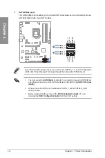
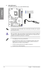
17. System Panel header
The System Panel header supports several chassis-mounted functions.
PLED
PLED
SPEAKER
HDD_LED
PWRSW
RESET
PIN 1
PLED+ PLED- PWRBTN# GND
+5V Ground Ground Speaker
HDD_LED-
Ground
RSTCON#
NC
PLED+
PLED-
PANEL
•
System power LED (2-pin PLED)
This 2-pin header is for the system power LED. Connect the chassis power LED cable
to this header. The system power LED lights up when you turn on the system power,
and blinks when the system is in sleep mode.
•
Hard disk drive activity LED (2-pin HDD_LED)
This 2-pin header is for the HDD Activity LED. Connect the HDD Activity LED cable
to this header. The HDD LED lights up or flashes when data is read from or written to
the HDD.
•
System warning speaker (4-pin SPEAKER)
This 4-pin header is for the chassis-mounted system warning speaker. The speaker
allows you to hear system beeps and warnings.
•
ATX power button/soft-off button (2-pin PWRSW)
This header is for the system power button. Pressing the power button turns the
system on or puts the system in sleep or soft-off mode depending on the operating
system settings. Pressing the power switch for more than four seconds while the
system is ON turns the system OFF.
•
Reset button (2-pin RESET)
This 2-pin header is for the chassis-mounted reset button for system reboot without
turning off the system power.
Summary of Contents for PRIME Z490-P
Page 1: ...Motherboard PRIME Z490 P ...
Page 34: ...1 22 Chapter 1 Product Introduction Chapter 1 ...
Page 36: ...2 2 Chapter 2 Basic Installation Chapter 2 ...
Page 39: ...PRIME Z490 P 2 5 Chapter 2 2 1 3 DIMM installation To remove a DIMM ...
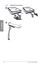
Page 44: ...2 10 Chapter 2 Basic Installation Chapter 2 2 1 7 SATA device connection OR ...
Page 51: ...PRIME Z490 P 2 17 Chapter 2 Connect to 5 1 channel Speakers Connect to 7 1 channel Speakers ...