background image

ASUS PCI-SC896 User’s Manual

11

1. Introduction

1. Introduction

1.3 Interface Descriptions

This section provides a more detailed explanation about the PCI Interface, the
SCSI Interface, the SCSI Activity LED Interface, and Wide Ultra2 SCSI.

1.3.1 The PCI Interface

PCI is a high-speed standard local bus for interfacing a number of I/O compo-
nents to a PC processor and memory subsystem. The PCI functionality for the
PCI-SC896 is contained within the ASUS PCI-SC896 PCI-SCSI I/O Processor
chip. The PCI-SC896 connects directly to the PCI bus and generates timing
protocol in compliance with the PCI specification. The PCI interface operates as
a 32-bit DMA bus master. The connection is made through the edge connector
J1. The signal definitions and pin numbers conform to the PCI Local Bus Speci-
fication Revision 2.1 standard. The PCI-SC896 conforms to the PCI universal
signaling environment for a 5 V or 3.3 V PCI bus.

1.3.2 The SCSI Interface

The SCSI functionality for the PCI-SC896 is contained within the ASUS PCI-
SC896 PCI-SCSI I/O Processor chip. The PCI-SC896 connects directly to the
two SCSI buses for SE or LVD SCSI applications and generates timing and
protocol in compliance with the SCSI standard. Each SCSI interface operates
at a burst transfer rate of up to 40 Mbyte per second for wide single-ended
transfers, and up to 80 Mbyte per second for wide LVD SCSI transfers.

The SCSI interfaces on the PCI-SC896 operates as two 16-bit, synchronous or
asynchronous, single-ended or LVD, and supports Ultra2 SCSI protocols and
16-bit arbitration. The PCI-SC896 board provides autosensing, dual mode SE/
LVD SCSI termination. Termination is normally enabled. When a SCSI device
is sensed to be connected to both internal and external connectors, termination
for that channel is automatically disabled. The PCI-SC896 supplies SCSI bus
TERMPWR (termination power) through a blocking diode and self-resetting
1.5 A short circuit protection device. An on-board LED lights up when
TERMPWR is shorted and turns off. A 40 MHz oscillator is installed on the
PCI-SC896 board to provide the clock frequency to the PCI-SC896 that is
necessary to support Wide Ultra2 SCSI transfers of up to 80 Mbytes/s.

Summary of Contents for PCI-SC896

Page 1: ...R PCI SC896 2Ch Ultra2 PCI SCSI Card USER S MANUAL ...

Page 2: ...ring in this manual may or may not be registered trademarks or copyrights of their respective companies and are used only for identification or explanation and to the owners benefit without intent to infringe ASUS and the ASUS logo are registered trademarks of ASUS Corporation Intel i386 i486 i486DX2 and Pentium are trademarks of Intel Corporation IBM and OS 2 are registered trademarks of Internat...

Page 3: ...w FTP ftp asus com tw pub ASUS ASUS COMPUTER INTERNATIONAL America Marketing Address 6737 Mowry Avenue Mowry Business Center Building 2 Newark CA 94560 USA Fax 1 510 608 4555 Email info usa asus com tw Technical Support Fax 1 510 608 4555 BBS 1 510 739 3774 Email tsd asus com WWW www asus com FTP ftp asus com Pub ASUS ASUS COMPUTER GmbH Europe Marketing Address Harkortstr 25 40880 Ratingen BRD Ger...

Page 4: ...ning the equipment off and on the user is encouraged to try to correct the interfer ence by one or more of the following measures Re orient or relocate the receiving antenna Increase the separation between the equipment and receiver Connect the equipment to an outlet on a circuit different from that to which the receiver is connected Consult the dealer or an experienced radio TV technician for hel...

Page 5: ...terface 10 1 2 2 SCSI Interface 10 1 2 3 Board Characteristics 10 1 3 Interface Descriptions 11 1 3 1 The PCI Interface 11 1 3 2 The SCSI Interface 11 1 3 4 Wide Ultra2 SCSI 12 2 Installing the PCI SC896 Host Adapter 13 2 1 Quick Installation Procedure 13 2 2 Detailed Installation Procedure 15 2 2 1 Before You Start 15 2 2 2 Inserting Your Host Adapter 16 2 2 3 Connecting Your SCSI Peripherals 17 ...

Page 6: ...I Connections 19 2 3 3 Internal and External SCSI Connections 19 2 3 4 Setting SCSI IDs 20 2 4 Setting Interrupts 20 3 Configuring the Host Adapter 21 3 1 When to Configure the PCI SC896 21 3 2 Starting the SCSI BIOS Utility 22 3 3 Exiting the SCSI BIOS Utility 28 4 Glossary of Terms and Abbreviations 29 Contents ...

Page 7: ... following chapters and appendixes Chapter 1 Using the PCI SC896 Host Adapter defines the interfaces and characteristics of the SYM22910 Dual Channel PCI to Ultra2 SCSI Host Adapter Board Chapter 2 Installing the PCI SC896 HostAdapter provides both quick and detailed installation instructions Chapter 3 Configuring the PCI SC896 HostAdapter describes the SCSI BIOS Configuration Utility to configure...

Page 8: ... command lines and names italics indicate user vari ables Italicized text must be re placed with appropriate user specified items Enter items of the type called for using lower case When an underscore appears in an italicized string enter a user supplied item of the type called for with no spaces Names of menu commands options check buttons text buttons options buttons text boxes list boxes etc ar...

Page 9: ...ns for your computer using only one PCI slot This board supports legacy Fast SCSI devices Ultra SCSI devices and the newest Ultra2 SCSI devices ASUS SCSI Device Management System SDMS software operates the board but the design of the board does not prevent other software to be used with it BIOS support for this host adapter is incorporated on the board in a 128K Flash device This guide and the PCI...

Page 10: ...8 pin high density for each internal channel A B One 50 pin fast SCSI connector for channel B Fast Ultra and Ultra2 data transfer capability SCSI TERMPWR source with autoresetting circuit breaker and TERMPWR shorted LED for each channel SCSI Plug and Play SCAM SCSI Configured AutoMatically See Chapter 3 Configuring the Host Adapter for further details about SCAM capability Flash EEPROM for BIOS st...

Page 11: ...ined within theASUS PCI SC896 PCI SCSI I O Processor chip The PCI SC896 connects directly to the two SCSI buses for SE or LVD SCSI applications and generates timing and protocol in compliance with the SCSI standard Each SCSI interface operates at a burst transfer rate of up to 40 Mbyte per second for wide single ended transfers and up to 80 Mbyte per second for wide LVD SCSI transfers The SCSI int...

Page 12: ... Host Adapter for a detailed explanation of SCSI bus connections When you purchased the PCI SC896 host adapter kit the cable provided in the kit is matched for a Fast Ultra Ultra2 SE or LVD operation This cable also has built in LVD termination since most Ultra2 hard disk drives are not made with onboard LVD termination Standard Cables Maximum Bus Length 1 STA Term Single Ended LVD Maximum Devices...

Page 13: ...er s manual that was sup plied with your computer and perform the following steps 1 Ground yourself before removing this host adapter board Remove the PCI SC896 Dual Channel PCI to Ultra2 SCSI Host Adapter board from the packing and check that it is not damaged 2 Remove the cabinet cover on your computer to access the PCI slots Refer to the user s manual for your computer CAUTION Ground yourself b...

Page 14: ...CSI bus connections 7 If you are connecting any internal SCSI devices plug a 68 pin connector on the end of the internal SCSI ribbon cable into the connector J4 or J5 Make certain to match pin 1 on both connectors Chain your internal devices on this cable 8 Connect your computer s LED cable if desired This LED cable drives the front panel LED found on most PC cabinets to indicate activity on the S...

Page 15: ...t look through the task list below to get an overall idea of the steps to perform Open your PC cabinet and select an open PCI slot Insert your host adapter Connect your SCSI peripherals Internal External Terminate the SCSI bus Set the peripheral SCSI IDs Make any configuration changes Close your PC cabinet Install your software The SCSI host adapter acts on your computer s behalf as the host to yo...

Page 16: ...o not touch board components or gold connector contacts The use of a static ground strap is recommended 4 Locate the slots for PCI plug in board installation Refer to the user s manual for your computer to confirm the location of the PCI slots The PCI SC896 requires a PCI slot that allows bus master operation 5 Remove the blank panel on the back of the computer aligned with the PCI slot that you i...

Page 17: ... one end of a wide internal SCSI ribbon cable into the connection J4 or J5 2 Plug the 68 pin connector on the other end of the internal SCSI ribbon cable into the SCSI connector on the internal SCSI device Pin 1 must match on all connections 3 To plug in additional internal SCSI devices use an internal SCSI ribbon cable with the required number of connectors attached along its length Make sure to ...

Page 18: ... of resistors called terminators All other SCSI devices on the bus must have their terminators removed or disabled REMEMBER The PCI SC896 host adapter is also on the SCSI bus and its termination is automatically enabled when it is connected to the end of the bus Low voltage differential peripheral devices are normally terminated with ex ternal terminators but are sometimes set with jumpers or with...

Page 19: ... 2 External SCSI Connections If only external SCSI device connections to your host adapter have been made then terminate the last external device on the SCSI bus You must disable the termination on all other devices Termination on your host adapter is automati cally enabled in this case 2 3 3 Internal and External SCSI Connections If internal and external SCSI devices are connected to your host ad...

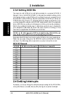
Page 20: ... the peripheral manufacturer s instructions and to the user s manual for your computer to determine the ID of each device and how to change it You must have no duplication of SCSI IDs on a SCSI bus NOTE As SCAM support is OFF by default for the PCI SC896 you may choose to turn this ON to assist in assigning SCSI IDs Determine the SCSI ID of each device on the SCSI bus Note any duplications Make an...

Page 21: ...you should not need to change the default configuration of your host adapter You may decide to alter these default values if there is a conflict between device settings or if you need to optimize system performance The following tables list the configuration settings you can change The global settings effect your host adapter and all SCSI devices which are connected to it The device settings effec...

Page 22: ...SCSI BIOS in a banner displayed on your computer monitor during boot If the utility is available the following message also appears on your monitor Press Ctrl C to start ASUS Configuration Utility This message remains on your screen for about five seconds giving you time to start the utility If you decide to press Ctrl C the message changes to Please wait invoking ASUS Configuration Utility After ...

Page 23: ...ght op tions They are described in detail below If these settings are altered the sys tem reboots upon exit from the configuration utility using the Quit option 3 2 1 1 Change Adapter Status The change adapter status allows you to activate or deactivate a host adapter and all SCSI devices attached to it When this option is used to make a change the change takes place after a reboot that is automat...

Page 24: ... during boot For more com plete information choose the verbose setting For a faster boot choose the terse setting 3 2 1 5 Mono Color Mono color allows you to choose between a monochrome or color display for the SCSI BIOS Configuration utility You might need to choose the mono set ting to get a more readable screen on a monochrome monitor 3 2 1 6 Language If enabled the Language option allows you t...

Page 25: ...tings will not be changed to reflect the new BIOS defaults Go into the Configuration Utility to change settings Parity The ASUS PCI to SCSI host adapters always generate parity but some older SCSI devices do not Therefore you are offered the option of dis abling parity checking NOTE When disabling parity checking it is also necessary to disable disconnects for all devices as parity checking for th...

Page 26: ... sector CHS values that will be mapped onto a disk without pre existing partitioning information SCSI Plug and Play Mapping is the default value To support interchange with noncompatible systems there is another option that can be selected by choos ing CHS Mapping and then cursoring to Alternate CHS Mapping NOTE Neither of these options will have any affect after the disk has been partitioned with...

Page 27: ...from the initiator during an I O transfer This disconnect frees the SCSI Bus to allow other I O processes This option tells the host adapter whether or not to allow a device to disconnect Some devices run faster with disconnects enabled mostly newer devices while some run faster with disconnects disabled mostly older de vices Read Write I O Time out seconds This option sets the amount of time the ...

Page 28: ... device Press ESC to abort Else press any key to continue Help This option brings up a help screen with information about the current menu Restore Default Setup This option resets all device selections back to their optimal settings Select this option to restore all manufacturing defaults for the specified adapter Note that all user customized options will be lost upon sav ing after restoring defa...

Page 29: ...s are made via taps on the lines Bus Mastering A high performance way to transfer data The host adapter controls the transfer of data directly to and from system memory without both ering the computer s microprocessor This is the fastest way for multitasking operating systems to transfer data Byte A unit of information consisting of eight bits Chain A topology in which every processor is connected...

Page 30: ...dard Architecture An extension of the 16 bit ISA bus standard It allows devices to perform 32 bit data transfers External SCSI Device A SCSI device installed outside the computer cabi net These devices are connected in a continuous chain using specific types of shielded cables Fast SCSI Astandard for SCSI data transfers It allows a transfer rate of up to 10 Mbytes s over an 8 bit SCSI bus and up t...

Page 31: ...sumption dataintegrity cablelengthsandsupportformultiple devices while providing a migration path for increased I O performance Mbyte Megabyte A measure of computer storage equal to 1024 kilobytes Main Memory The part of a computer s memory which is directly acces sible by the CPU usually synonymous with RAM Motherboard Mainboard A large circuit board that holds RAM ROM themicroprocessor customint...

Page 32: ...ansfer data to and from memory via the computer s I O ports PIO is usually faster than DMA but requires CPU time PortAddress Also Port Number The address through which commands are sent to a host adapter board This address is assigned by the PCI bus Port Number See Port Address Queue Tags A way to keep track of multiple commands that allows for in creased throughput on the SCSI bus RAM Random Acce...

Page 33: ... for Wide SCSI The host adapter usually gets ID 7 giving it priority to control the bus SDMS SCSI Device Management System An ASUS software product that manages SCSI system I O STA SCSI Trade Association A group of companies that cooperate to pro mote SCSI parallel interface technology as a viable mainstream I O intercon nect for commercial computing Single Ended SCSI A hardware specification for ...

Page 34: ...bit SCSIbus STA SCSITradeAssociation supportsusingtheterm Ultra2SCSI over the older term Fast 40 VCCI Voluntary Control Council for Interference VHDCI Very High Density Cable Interconnect A trapezoidal shielded con nector that has a 0 8 mm pitch Wide SCSI A SCSI 2 feature allowing 16 or 32 bit transfers on the SCSI bus This dramatically increases the transfer rate over the standard 8 bit SCSI bus ...

Reviews: