background image

ASUS P8P67 REV 3.1

2-25

Chapter 2

4. 

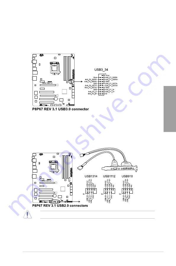
USB 3.0 connector (20-1 pin USB3_34)

This connector is for the additional USB 3.0 ports, and complies with USB 3.0 

specification that supports up to 480 MBps connection speed. If the USB 3.0 front 

panel cable is available from your system chassis, with this USB 3.0 connector, you 

can have a front panel USB 3.0 solution.

Never connect a 1394 cable to the USB connectors. Doing so will damage the motherboard!

5. 

USB 2.0 connectors (10-1 pin USB910, USB1112, USB1314)

These connectors are for USB 2.0 ports. Connect the USB module cable to any of 

these connectors, then install the module to a slot opening at the back of the system 

chassis. These USB connectors comply with USB 2.0 specification that supports up to 

48 Mbps connection speed.

Summary of Contents for P8P67 LX

Page 1: ...Motherboard P8P67 REV 3 1 ...

Page 2: ...lanation and to the owners benefit without intent to infringe Offer to Provide Source Code of Certain Software This product may contain copyrighted software that is licensed under the General Public License GPL and under the Lesser General Public License Version LGPL The GPL and LGPL licensed code in this product is distributed without any warranty Copies of these licenses are included in this pro...

Page 3: ...herboard overview 2 2 2 2 1 Motherboard layout 2 2 2 2 2 Central Processing Unit CPU 2 4 2 2 3 System memory 2 5 2 2 4 Expansion slots 2 14 2 2 5 Onboard switches 2 16 2 2 6 Onboard LEDs 2 19 2 2 7 Jumper 2 21 2 2 8 Internal connectors 2 22 2 3 Building your computer system 2 32 2 3 1 Additional tools and components to build a PC system 2 32 2 3 2 CPU installation 2 33 2 3 3 CPU heatsink and fan a...

Page 4: ... 3 5 6 Onboard Devices Configuration 3 19 3 5 7 APM 3 21 3 6 Monitor menu 3 23 3 7 Boot menu 3 26 3 8 Tools menu 3 28 3 8 1 ASUS EZ Flash Utility 3 28 3 8 2 ASUS O C Profile 3 28 3 9 Exit menu 3 30 3 10 Updating BIOS 3 31 3 10 1 ASUS Update utility 3 31 3 10 2 ASUS EZ Flash Utility 3 34 3 10 3 ASUS CrashFree BIOS 3 utility 3 35 3 10 4 ASUS BIOS Updater 3 36 Chapter 4 Software support 4 1 Installin...

Page 5: ...ROM utility 4 19 4 5 Creating a RAID driver disk 4 23 4 5 1 Creating a RAID driver disk without entering the OS 4 23 4 5 2 Creating a RAID driver disk in Windows 4 23 4 5 3 Installing the RAID driver during Windows OS installation 4 24 4 5 4 Using a USB floppy disk drive 4 25 Chapter 5 ATI CrossFireX technology support 5 1 ATI CrossFireX technology 5 1 5 1 1 Requirements 5 1 5 1 2 Before you begin...

Page 6: ...nt from that to which the receiver is connected Consult the dealer or an experienced radio TV technician for help Canadian Department of Communications Statement This digital apparatus does not exceed the Class B limits for radio noise emissions from digital apparatus set out in the Radio Interference Regulations of the Canadian Department of Communications This class B digital apparatus complies ...

Page 7: ...your area If you are not sure about the voltage of the electrical outlet you are using contact your local power company If the power supply is broken do not try to fix it by yourself Contact a qualified service technician or your retailer Operation safety Before installing the motherboard and adding devices on it carefully read all the manuals that came with the package Before using the product en...

Page 8: ...IOS Setup menus Detailed descriptions of the BIOS parameters are also provided Chapter 4 Software support This chapter describes the contents of the support DVD that comes with the motherboard package and the software Chapter 5 ATI CrossFireX technology support This chapter describes how to install and configure multiple ATI CrossFireX graphics cards Where to find more information Refer to the fol...

Page 9: ... must press the enclosed key Example Enter means that you must press the Enter or Return key Key1 Key2 Key3 If you must press two or more keys simultaneously the key names are linked with a plus sign Example Ctrl Alt Del DANGER WARNING Information to prevent injury to yourself when trying to complete a task CAUTION Information to prevent damage to the components when trying to complete a task IMPO...

Page 10: ...to the physical characteristics of individual CPUs Some hyper DIMMs only support one DIMM per channel Please refer to Memory QVL for details Refer to www asus com or this user manual for the Memory QVL Qualified Vendors Lists Expansion slots 1 x PCI Express 2 0 x16 slot blue single at x16 1 x PCI Express 2 0 x16 slot black max at x4 mode compatible with PCIe x1 and x4 devices 2 x PCI Express 2 0 x...

Page 11: ...0 ports 6 ports at midboard 6 ports at back panel ASUS unique features ASUS Dual Intelligent Processors 2 with DIGI VRM ASUS DIGI VRM Industry leading Digital 12 2 Phase Power Design ASUS DIGI VRM Utility ASUS EPU EPU EPU switch ASUS TPU Auto Tuning TurboV TPU switch ASUS BT GO Bluetooth Folder Sync BT Transfer Shot Send BT to Net Music Player Personal Manager ASUS BT Turbo Remote Exclusive Smartp...

Page 12: ...1 ports 8 channel Audio I O ports Internal I O connectors 1 x USB 3 0 2 0 connector supports additional 2 USB ports 19 pin 3 x USB 2 0 1 1 connectors support additional 6 USB ports 4 x SATA 6 0 Gb s connectors 2 x gray 2 x navy blue 4 x SATA 3 0 Gb s connectors blue 1 x CPU Fan connector 4 pin 2 x Chassis Fan connectors 1 x 4 pin 1 x 3 pin 1 x Power Fan connector 3 pin 1 x IEEE1394a connector 1 x ...

Page 13: ...ith the list below 1 2 Package contents Check your motherboard package for the following items If any of the above items is damaged or missing contact your retailer The illustrated items above are for reference only Actual product specifications may vary with different models Chapter 1 Product introduction Chapter 1 UserManual ASUS P8P67 REV 3 1 motherboard User guide Support DVD 2 x Serial ATA 6 ...

Page 14: ...reX The motherboard features the most powerful Intel P67 platform to optimize PCIe allocation in multiple GPU configurations Expect a brand new gaming style you ve never experienced before Dual Channel DDR3 2200 O C 2133 O C 1866 O C 1600 1333 1066 Support The motherboard supports DDR3 memory that features data transfer rates of 2200 O C 2133 O C 1866 O C 1600 1333 1066 MHz to meet the higher band...

Page 15: ...on power intelligently adjusting PWM voltage and frequency modulation to minimize power loss while performance reaches its full potential 2X Less Radiation ASUS DIGI VRM adjusts frequencies dynamically cutting radiation by half to enhance system stability through enabling spread spectrum TPU Unleash your performance with ASUS simple onboard switch or AI Suite II utility The TPU chip offers precise...

Page 16: ...heatsink will give users an extremely silent and cooling experience with the elegant appearance ASUS Fan Xpert ASUS Fan Xpert intelligently allows you to adjust both the CPU and chassis fan speeds according to different ambient temperatures caused by different climate conditions in different geographic regions and your PC s loading The built in variety of useful profiles offer flexible controls of...

Page 17: ...urround experience through the most common PC audio setups your existing stereo speakers or headphones In addition to virtual surround Bass enhancement provides stronger low frequency bass sound and Voice clarification provides clear human dialogue even with loud background sound With these technologies you may experience a better home theater audio with ease ErP Ready The motherboard is European ...

Page 18: ...1 6 Chapter 1 Product Introduction Chapter 1 ...

Page 19: ...bject such as the power supply case to avoid damaging them due to static electricity Hold components by the edges to avoid touching the ICs on them Whenever you uninstall any component place it on a grounded antistatic pad or in the bag that came with the component Before you install or remove any component ensure that the ATX power supply is switched off or the power cord is detached from the pow...

Page 20: ...dware information Chapter 2 Refer to 2 2 8 Internal Connectors and 2 3 10 Rear panel connection for more information about internal connectors and rear panel connectors 2 2 Motherboard overview 2 2 1 Motherboard layout ...

Page 21: ...al ATA 6 0 Gb s connectors 7 pin SATA6G_E1 E2 navy blue 2 24 9 Intel P67 Serial ATA 6 0 Gb s connectors 7 pin SATA6G_1 2 gray 2 22 10 Intel P67 Serial ATA 3 0 Gb s connectors 7 pin SATA3G_3 6 blue 2 23 11 System panel connector 20 8 pin PANEL 2 31 12 Serial port connector 10 1 pin COM1 2 30 13 Clear RTC RAM 3 pin CLRTC 2 21 14 Standby power LED 2 19 15 USB 2 0 connectors 10 1 pin USB910 USB1112 US...

Page 22: ...act your retailer immediately if the PnP cap is missing or if you see any damage to the PnP cap socket contacts motherboard components ASUS will shoulder the cost of repair only if the damage is shipment transit related Keep the cap after installing the motherboard ASUS will process Return Merchandise Authorization RMA requests only if the motherboard comes with the cap on the LGA1155 socket The p...

Page 23: ... configurations 2 2 3 System memory The motherboard comes with four Double Data Rate 3 DDR3 Dual Inline Memory Modules DIMM slots A DDR3 module is notched differently from a DDR or DDR2 module DO NOT install a DDR or DDR2 memory module to the DDR3 slot ...

Page 24: ...32 bit Windows OS when you install 4GB or more memory on the motherboard the actual usable memory for the OS can be about 3GB or less For effective use of memory we recommend that you do any of the following Use a maximum of 3GB system memory if you are using a 32 bit Windows OS Install a 64 bit Windows OS when you want to install 4GB or more on the motherboard For more details refer to the Micros...

Page 25: ...GB2133C9DC XMP 4GB 2 x 2GB DS 9 9 9 28 1 65 GEIL GU34GB2133C9DC XMP 4GB 2 x 2GB DS 9 9 9 28 1 65 KINGSTON KHX2133C8D3T1K2 4GX XMP 4GB 2 x 2GB DS 8 1 65 KINGSTON KHX2133C9D3T1K2 4GX XMP 4GB 2 x 2GB DS 9 1 65 Patriot PVV34G2133C9K XMP 4GB 2 x 2GB DS 9 11 9 27 1 66 P8P67 REV 3 1 Motherboard Qualified Vendors Lists QVL DDR3 2133 O C MHz capability Vendors Part No Size SS DS Chip Brand Chip NO Timing V...

Page 26: ...STON KHX2000C9AD3T1K3 3GX XMP 3GB 3 x 1GB SS 1 65 KINGSTON KHX2000C9AD3T1K2 4GX XMP 4GB 2 x 2GB DS 9 1 65 KINGSTON KHX2000C9AD3W1K2 4GX XMP 4GB 2 x 2GB DS 9 1 65 KINGSTON KHX2000C9D3T1K2 4GX XMP 4GB 2 x 2GB DS 1 65 KINGSTON KHX2000C9AD3T1K3 6GX XMP 6GB 3 x 2GB DS 9 1 65 KINGSTON KHX2000C9AD3T1K3 6GX XMP 6GB 3 x 2GB DS 1 65 KINGSTON KHX2000C9AD3W1K3 6GX XMP 6GB 3 x 2GB DS 9 1 65 OCZ OCZ3G2000LV6GK ...

Page 27: ...2GB 2 x 1GB SS 1 6 G SKILL F3 12800CL9D 4GBNG 4GB 2 x 2GB SS 1 6 G SKILL F3 12800CL9D 4GBRL 4GB 2 x 2GB SS 1 6 G SKILL F3 12800CL7D 8GBRH XMP 4GB 2 x 2GB DS 7 8 7 24 1 6 G SKILL F3 12800CL8D 8GBECO XMP 4GB 2 x 2GB DS 8 8 8 24 1 35 G SKILL F3 12800CL9D 8GBRL XMP 4GB 2 x 2GB DS 9 9 9 24 1 5 G SKILL F3 12800CL7D 4GBRM XMP 4GB 2 x 2GB DS 7 8 7 24 1 6 G SKILL F3 12800CL7D 4GBECO XMP 4GB 2 x 2GB DS 7 8 ...

Page 28: ...S 8 8 8 24 1 65 Team TXD31024M1600C8 D XMP 1GB SS Team T3D1288RT 16 8 8 8 24 1 65 Team TXD32048M1600C8 D XMP 2GB DS Team T3D1288RT 16 8 8 8 24 1 65 Team TXD32048M1600HC8 D XMP 2GB DS Team T3D1288RT 16 8 8 8 24 1 65 Vendors Part No Size SS DS Chip Brand Chip NO Timing Voltage DIMM socket support Optional 1 DIMM 2 DIMM 4 DIMM A DATA SU3U1333B1G9 B 1GB SS Hynix H5TQ1G83TFR A DATA SU3U1333B2G9 B 2GB D...

Page 29: ...3GB 3 x 1GB SS 7 7 7 1 65 OCZ OCZ3G1333ULV4GK 4GB 2 x 2GB DS 8 8 8 1 35 OCZ OCZ3P1333LV4GK 4GB 2 x 2GB DS 1 65 OCZ OCZ3RPR13334GK 4GB 2 x 2GB DS 6 6 6 1 75 OCZ OCZ3G1333ULV4GK 4GB 2 x 2GB DS 8 8 8 1 65 OCZ OCZ3P1333LV4GK 4GB 2 x 2GB DS 7 7 7 1 65 OCZ OCZ3G1333LV6GK 6GB 3 x 2GB DS 9 9 9 1 65 OCZ OCZX1333LV6GK XMP 6GB 3 x 2GB DS NA 8 8 8 1 6 OCZ OCZ3G1333LV8GK 8GB 2 x 4GB DS 9 9 9 1 65 PSC AL7F8G73D...

Page 30: ...GB SS MICRON D9KPT ECC 7 MICRON MT16JTF25664AZ 1G1F1 2GB DS MICRON 8ZF22 D9KPV 7 MICRON MT16JTF25664AZ 1G1F1 2GB DS MICRON D9KPT 7 MICRON MT18JSF25672AZ 1G1F1 2GB DS MICRON D9KPT ECC 7 SAMSUNG M378B5273BH1 CF8 4GB DS SAMSUNG K4B2G0846B HCF8 8 1 5 Elixir M2Y2G64CB8HA9N BE 2GB DS Elixir M2Y2G64CB8HC5N BE 2GB DS Elixir N2CB1G80CN BE Elixir M2Y2G64CB8HC9N BE 2GB DS WINTEC 3DU3191A 10 1GB DS Qimonda ID...

Page 31: ...ts as one pair of Dual channel memory configuration We suggest that you install the modules into slots A2 and B2 for better compatibility 4 DIMMs Supports four 4 modules inserted into both the blue and black slots as two pairs of Dual channel memory configuration ASUS exclusively provides hyper DIMM support function Hyper DIMM support is subject to the physical characteristics of individual CPUs L...

Page 32: ...board components Slot No Slot Description 1 PCIe 2 0 x1_1 slot 2 PCIe 2 0 x16_1 slot blue single at x16 mode 3 PCIe 2 0 x1_2 slot 4 PCI slot 1 5 PCIe 2 0 x16_2 slot black at max x4 mode compatible with PCIe x1 x2 and x4 devices 6 PCI slot 2 7 PCI slot 3 VGA configuration PCI Express operating mode PCIe 2 0 x16_1 PCIe 2 0 x16_2 Single VGA PCIe card x16 Recommend for single VGA N A Dual VGA PCIe car...

Page 33: ...mance In CrossFireX mode use the PCIe 2 0 x16_1 and PCIe 2 0 x16_2 slots for PCI Express x16 graphics cards to get better performance To achieve the optimum performance for CrossFireX mode set the PCI Express X16_2 slot black bandwidth BIOS item to x4 mode Refer to page 3 20 for details We recommend that you provide sufficient power when running CrossFireX mode Refer to page 2 28 for details Conne...

Page 34: ...ds for the system to test one set of failsafe settings If the test fails the system reboots and test the next set of failsafe settings The blinking speed of the DRAM_LED increases indicating different test processes Due to memory tuning requirement the system automatically reboots when each timing set is tested If the installed DIMMs still fail to boot after the whole tuning process the DRAM_LED l...

Page 35: ...e TPU switch lights when the switch setting is turned to Enable Refer to section 2 2 6 Onboard LEDs for the exact location of the TPU LED If you change the switch setting to Enable under the OS environment the TPU function will be activated after the next system bootup You may use the TurboV and Auto Tuning feature in the TurboV EVO application adjust the BIOS setup program or enable the TPU switc...

Page 36: ... off The EPU LED O2LED2 near the EPU switch lights when the switch setting is turned to Enable Refer to section 2 2 6 Onboard LEDs for the exact location of the EPU LED If you change the switch setting to Enable under the OS environment the EPU function will be activated after the next system bootup You may change the EPU settings in the software application or BIOS setup program and enable the EP...

Page 37: ...dly design provides an intuitional way to locate the root problem within a second 2 Standby power LED The motherboard comes with a standby power LED that lights up to indicate that the system is ON in sleep mode or in soft off mode This is a reminder that you should shut down the system and unplug the power cable before removing or plugging in any motherboard component The illustration below shows...

Page 38: ...2 20 Chapter 2 Hardware information Chapter 2 3 TPU LED The TPU LED lights when the TPU switch is turned to Enable 4 EPU LED The EPU LED lights when the EPU switch is turned to Enable ...

Page 39: ...s 2 3 Keep the cap on pins 2 3 for about 5 10 seconds then move the cap back to pins 1 2 3 Plug the power cord and turn ON the computer 4 Hold down the Del key during the boot process and enter BIOS setup to re enter data If the steps above do not help remove the onboard battery and move the jumper again to clear the CMOS RTC RAM data After the CMOS clearance reinstall the battery You do not need ...

Page 40: ...set to AHCI Mode by default If you intend to create a Serial ATA RAID set using these connectors set the SATA Mode item in the BIOS to RAID Mode Refer to section 3 5 4 SATA Configuration for details When using NCQ set the SATA Mode item in the BIOS to AHCI Mode Refer to section 3 5 4 SATA Configuration for details Before creating a RAID set refer to section 4 4 RAID configurations or the manual bu...

Page 41: ...AHCI Mode by default If you intend to create a Serial ATA RAID set using these connectors set the SATA Mode item in the BIOS to RAID Mode Refer to section 3 5 4 SATA Configuration for details When using NCQ set the SATA Mode item in the BIOS to AHCI Mode Refer to section 3 5 4 SATA Configuration for details Before creating a RAID set refer to section 4 4 RAID configurations or the manual bundled i...

Page 42: ...es via Serial ATA 6 0 Gb s signal cables The SATA6G_E1 E2 navy blue connectors are for data drives only ATAPI device is not supported You must install Windows XP Service Pack 3 or later versions before using Serial ATA hard disk drives When using NCQ set the Marvell Storage Controller item in the BIOS to AHCI Mode Refer to section 3 5 7 Onboard Devices Configuration for details ...

Page 43: ...with this USB 3 0 connector you can have a front panel USB 3 0 solution Never connect a 1394 cable to the USB connectors Doing so will damage the motherboard 5 USB 2 0 connectors 10 1 pin USB910 USB1112 USB1314 These connectors are for USB 2 0 ports Connect the USB module cable to any of these connectors then install the module to a slot opening at the back of the system chassis These USB connecto...

Page 44: ... system chassis Never connect a USB cable to the IEEE 1394a connector Doing so will damage the motherboard The IEEE 1394a module is purchased separately 7 Digital audio connector 4 1 pin SPDIF_OUT This connector is for an additional Sony Philips Digital Interface S PDIF port s Connect the S PDIF Out module cable to this connector then install the module to a slot opening at the back of the system ...

Page 45: ...s the CPU fan of maximum 1A 12 W fan power Only the CPU_FAN CHA_FAN 1 and CHA_FAN 2 connectors support the ASUS FAN Xpert feature If you install two VGA cards we recommend that you plug the rear chassis fan cable to the motherboard connector labeled CHA_FAN1 or CHA_FAN2 for better thermal environment Do not forget to connect the fan cables to the fan connectors Insufficient air flow inside the sys...

Page 46: ... of the motherboard s high definition audio capability If you want to connect a high definition front panel audio module to this connector set the Front Panel Type item in the BIOS setup to HD if you want to connect an AC 97 front panel audio module to this connector set the item to AC97 By default this connector is set to HD 10 ATX power connectors 24 pin EATXPWR 8 pin EATX12V These connectors ar...

Page 47: ...gabyte P610A C1 AcBel API5PC36 GoldenField ATX S398 AcBel PC6018 GoldenField ATX S550 AMA AA1200U C GreatWall BTX 600SE AMA AA1000U C HECHUAN ST ATX330 Antec SG 850 Huntkey R85 Antec EA 380 Huntkey 磐石500 ASUS P 50GA I cute AP 600S ASUS P 55GA In Win COMMANDER IRP COM1500 ASUS U 65GA OCZ 1000PXS ASUS U 75HA OCZ 780MXS Be quiet BN073 SAMA YUHUI 350P Be quiet BN077 Seasonic SS 500GB Be quiet P6 PRO 8...

Page 48: ...11 Serial port connector 10 1 pin COM1 This connector is for a serial COM port Connect the serial port module cable to this connector then install the module to a slot opening at the back of the system chassis The COM module is purchased separately ...

Page 49: ...arning speaker 4 pin SPEAKER This 4 pin connector is for the chassis mounted system warning speaker The speaker allows you to hear system beeps and warnings ATX power button soft off button 2 pin PWRSW This connector is for the system power button Pressing the power button turns the system on or puts the system in sleep or soft off mode depending on the BIOS settings Pressing the power switch for ...

Page 50: ...to build a PC system 1 bag of screws Philips cross screwdriver PC chassis Power supply unit Intel LGA 1155 CPU Intel LGA 1155 compatible CPU Fan DDR3 DIMM SATA hard disk drive SATA optical disc drive optional Graphics card optional The tools and components in the table above are not included in the motherboard package ...

Page 51: ...ASUS P8P67 REV 3 1 2 33 Chapter 2 A B 1 2 3 2 3 2 CPU installation The LGA1156 CPU is incompatible with the LGA1155 socket DO NOT install a LGA1156 CPU on the LGA1155 socket ...

Page 52: ...2 34 Chapter 2 Hardware information Chapter 2 C B A 5 6 4 ...

Page 53: ...r 2 2 3 3 CPU heatsink and fan assembly installation Apply the Thermal Interface Material to the CPU heatsink and CPU before you install the heatsink and fan if necessary To install the CPU heatsink and fan assembly 2 B B A A 1 3 4 ...

Page 54: ...2 36 Chapter 2 Hardware information Chapter 2 To uninstall the CPU heatsink and fan assembly 2 A B B A 1 ...

Page 55: ...ASUS P8P67 REV 3 1 2 37 Chapter 2 1 2 3 To remove a DIMM 2 3 4 DIMM installation B A ...

Page 56: ...ter 2 Hardware information Chapter 2 2 3 5 Motherboard installation 2 1 The diagrams in this section are for reference only The motherboard layout may vary with models but the installation steps remain the same ...

Page 57: ...ASUS P8P67 REV 3 1 2 39 Chapter 2 DO NOT overtighten the screws Doing so can damage the motherboard 3 ...

Page 58: ...2 40 Chapter 2 Hardware information Chapter 2 2 3 6 ATX Power connection 1 2 OR OR ...

Page 59: ...ASUS P8P67 REV 3 1 2 41 Chapter 2 2 3 7 SATA device connection OR 2 OR 1 ...

Page 60: ...information Chapter 2 2 3 8 Front I O Connector IDE_LED POWER SW RESET SW IDE_LED IDE_LED PWR Reset Ground Ground 1 2 USB 2 0 AAFP To install ASUS Q Connector To install USB 2 0 Connector To install front panel audio connector ...

Page 61: ...ASUS P8P67 REV 3 1 2 43 Chapter 2 2 3 9 Expension Card installation To install PCIe x16 cards To install PCIe x1 cards To install PCI cards ...

Page 62: ...RJ 45 port 11 Audio I O ports 6 PS 2 keyboard port purple Due to USB 3 0 controller limitation USB 3 0 devices can only be used under Windows OS environment and after the USB 3 0 driver installation USB 3 0 devices can only be used as data storage only We strongly recommend that you connect USB 3 0 devices to USB 3 0 ports for faster and better performance for your USB 3 0 devices and Refer to the...

Page 63: ...c In Mic In Mic In Mic In Orange Center Subwoofer Center Subwoofer Black Rear Speaker Out Rear Speaker Out Rear Speaker Out Gray Side Speaker Out LAN port LED indications SPEED LED ACT LINK LED LAN port Activity Link LED Speed LED Status Description Status Description OFF No link OFF 10 Mbps connection ORANGE Linked ORANGE 100 Mbps connection BLINKING Data activity GREEN 1 Gbps connection Bluetoot...

Page 64: ...2 46 Chapter 2 Hardware information 2 46 Chapter 2 Hardware information Chapter 2 Connect to Headphone and Mic Connect to Stereo Speakers Connect to 2 1 channel Speakers Connect to 4 1 channel Speakers ...

Page 65: ... 1 2 47 ASUS P8P67 REV 3 1 2 47 Chapter 2 Connect to 5 1 channel Speakers Connect to 7 1 channel Speakers When the DTS Surround Sensation UltraPC function is enabled ensure to connect the rear speaker to the gray port ...

Page 66: ...e the tests are running the BIOS beeps refer to the BIOS beep codes table below or additional messages appear on the screen If you do not see anything within 30 seconds from the time you turned on the power the system may have failed a power on test Check the jumper settings and connections or call your retailer for assistance 7 At power on hold down the Delete key to enter the BIOS Setup Follow t...

Page 67: ... up the computer the system provides you with the opportunity to run this program Press Del during the Power On Self Test POST to enter the Setup utility Otherwise POST continues with its test routines If you wish to enter Setup after POST press Ctrl Alt Delete or press the reset button on the system chassis to restart the system You can also turn the system off and then turn it back on to restart...

Page 68: ...0ºC 3 3V 3 344V 12V 12 248V CHA_FAN1 N A CHA_FAN2 N A English EFI BIOS Utility EZ Mode Friday 10 15 2010 Normal Quiet Performance Energy Saving System Performance Boot Menu F8 Default F5 Use the mouse to drag or keyboard to navigate to decide the boot priority Boot Priority Exits the BIOS setup program without saving the changes saves the changes and resets the system or enters the Advanced Mode S...

Page 69: ...l Storage Controller AHCI Mode Marvell Storage OPROM Enabled JMB Storage Controller Enabled JMB Storage OPROM Enabled Display OptionRom in POST Enabled Realtek LAN Enabled Realtek PXE OPROM Disabled Intel LAN Enabled Intel PXE OPROM Disabled Serial Port Configuration Menu bar The menu bar on top of the screen has the following main items Main For changing the basic system configuration Ai Tweaker ...

Page 70: ...n options for that item Scroll bar A scroll bar appears on the right side of a menu screen when there are items that do not fit on the screen Press the Up Down arrow keys or Page Up Page Down keys to display the other items on the screen Navigation keys At the bottom right corner of the menu screen are the navigation keys for the BIOS setup program Use the navigation keys to select items in the me...

Page 71: ... entered to boot or enter Setup In Setup the User will have Administrator rights Administrator Password Not Installed User Password Not Installed Administrator Password User Password Back Main Security EFI BIOS Utility Advanced Mode If you have forgotten your BIOS password erase the CMOS Real Time Clock RTC RAM to clear the BIOS password See section 2 2 7 Jumper for information on how to erase the...

Page 72: ...s Enter when prompted to create confirm the password After you clear the password the Administrator Password item on top of the screen shows Not Installed User Password If you have set a user password you must enter the user password for accessing the system The User Password item on top of the screen shows the default Not Installed After you set a password this item shows Installed To set a user ...

Page 73: ...uto DRAM Voltage 1 500V Auto VCCSA Voltage 0 925V Auto VCCIO Voltage 1 050V Auto CPU PLL Voltage 1 800V Auto PCH Voltage 0 975V Auto CPU Spread Spectrum Auto Main Ai Tweaker Advanced Monitor Boot Tool Exit Version 2 00 1201 Copyright C 2010 American Megatrends Inc X M P When XMP is enabled BLCK frequency CPU ratio and memory parameters will be auto optimized Select Screen Select Item Enter Select ...

Page 74: ...supported by your memory module Configuration options Disabled Profile 1 Profile 2 Memory Frequency Auto Allows you to set the memory operating frequency The configuration options vary with the BCLK PEG Frequency item settings Selecting a very high memory frequency may cause the system to become unstable If this happens revert to the default setting EPU Power Saving Mode Disabled Allows you to ena...

Page 75: ... Intel Turbo Mode Technology Enabled Allows processor cores to run faster than marked frequency in specific condition Disabled Disables this function The following three items appear only when you set the Enhanced Intel SpeedStep Technology and Turbo Mode items to Enabled Turbo Ratio Auto Allows you to manually adjust the Trubo CPU ratio Auto All Turbo ratio are set by Intel CPU default settings B...

Page 76: ...xtreme Configuration options Auto Regular Medium High Ultra High Extreme The actual performance boost may vary depending on your CPU specification VRM Frequency Auto Switching frequency will affect the VRM transient response and component thermal Higher frequency gets quicker transient response Configuration options Auto Manual VRM Spread Spectrum Disabled Enable Spread Spectrum to enhance system ...

Page 77: ...the desired values using the numeric keypad and press the Enter key You can also use the and keys to adjust the value To restore the default setting type auto using the keyboard and press the Enter key CPU Voltage Offset Mode Manual Mode Allows you to set a fixed CPU voltage Offset Mode Allows you to set the Offset voltage Offset Mode Sign This item appears only when you set the CPU Voltage item t...

Page 78: ...tage CPU Offset Voltage DRAM Voltage VCCSA Voltage VCCIO Voltage 1 8FSR Voltage and PCH Voltage items are labeled in different color indicating the risk levels of high voltage settings Refer to the table below for details The system may need better cooling system to work stably under high voltage settings CPU Spread Spectrum Auto Auto Automatic configuration Disabled Enhances the BCLK overclocking...

Page 79: ...nd other system devices Main Ai Tweaker Advanced Monitor Boot Tool Exit CPU Configuration Parameters EFI BIOS Utility Advanced Mode CPU Configuration System Agent Configuration PCH Configuration SATA Configuration USB Configuration Onboard Devices Configuration APM Version 2 00 1201 Copyright C 2010 American Megatrends Inc Select Screen Select Item Enter Select Change Opt F1 General Help F2 Previo...

Page 80: ...n 2 00 1201 Copyright C 2010 American Megatrends Inc Adjust Non Turbo Ratio Select Screen Select Item Enter Select Change Opt F1 General Help F2 Previous Values F5 Optimized Defaults F10 Save ESC Exit Back Advanced CPU Configuration EFI BIOS Utility Advanced Mode CPU Configuration Genuine Intel R CPU 0 3 00GHz EM64T Supported Processor Speed 3000 MHz Processor Stepping 206a3 Microcode Revision 8 P...

Page 81: ...s return to zero 0 Intel R Virtualization Technology Disabled Enabled Allows a hardware platform to run multiple operating systems separately and simultaneously enabling one system to virtually function as several systems Disabled Disables this function Enhanced Intel SpeedStep Technology Enabled Allows you to enable or disable the Enhanced Intel SpeedStep Technology EIST Disabled The CPU runs at ...

Page 82: ...CI Initiate Graphic Adapter PEG PCI Allows you to decide which graphics controller to use as the primary boot device Configuration options PCI PEG PEG PCI 3 5 3 PCH Configuration The South Bridge menu allows you to change the southbridge chipset settings Main Ai Tweaker Advanced Monitor Boot Tool Exit Enabled Disabled the High Precision Event Timer Back Advanced PCH Configuration EFI BIOS Utility ...

Page 83: ...d disk drives as Parallel ATA physical storage devices AHCI Mode Set to AHCI Mode when you want the SATA hard disk drives to use the AHCI Advanced Host Controller Interface The AHCI allows the onboard storage driver to enable advanced Serial ATA features that increases storage performance on random workloads by allowing the drive to internally optimize the order of commands RAID Mode Set to RAID M...

Page 84: ...am Auto Allows the system to detect the presence of USB devices at startup If detected the USB controller legacy mode is enabled If no USB device is detected the legacy USB support is disabled Legacy USB3 0 Support Enabled Enabled Enables the support for USB 3 0 devices on legacy operating systems OS Disabled Disables the function EHCI Hand off Disabled Enabled Enables the support for operating sy...

Page 85: ...F audio output HDMI Sets to HDMI for HDMI audio output VIA 1394 Enabled Enabled Enables the onboard IEEE 1394a controller Disabled Disables the controller Main Ai Tweaker Advanced Monitor Boot Tool Exit Version 2 00 1201 Copyright C 2010 American Megatrends Inc Enabled Disabled Azalia HD Audio Select Screen Select Item Enter Select Change Opt F1 General Help F2 Previous Values F5 Optimized Default...

Page 86: ...and allows you to enable or disable the OptionRom of the Marvell storage controller Configuration options Enabled Disabled Realtek LAN Controller Enabled Enabled Enables the Realtek LAN controller Disabled Disables the controller Realtek PXE OPROM Disabled This item appears only when you set the previous item to Enabled and allows you to enable or disable the PXE OptionRom of the Realtek LAN contr...

Page 87: ...the Power On by a PS 2 mouse Enabled Enables the Power On by a PS 2 mouse This feature requires an ATX power supply that provides at least 1A on the 5VSB lead Power On By PCI Disabled Disabled Disables the PME to wake up from S5 by PCI devices Enabled Allows you to turn on the system through a PCI LAN or modem card This feature requires an ATX power supply that provides at least 1A on the 5VSB lea...

Page 88: ...les Ring to generate a wake event Enabled Enables Ring to generate a wake event Power On By RTC Disabled Disabled Disables RTC to generate a wake event Enabled When set to Enabled the items RTC Alarm Date Days and Hour Minute Second will become user configurable with set values ...

Page 89: ...ield shows N A Select Ignore if you do not wish to display the detected speed Scroll down to display the following items Version 2 00 1201 Copyright C 2010 American Megatrends Inc 3 3V Voltage 3 312 V 5V Voltage 5 080 V 12V Voltage 12 192 V Anti Surge Support Enabled Main Ai Tweaker Advanced Monitor Boot Tool Exit Version 2 00 1201 Copyright C 2010 American Megatrends Inc Select Screen Select Item...

Page 90: ...ng four items appear only when you set CPU Fan Profile to Manual CPU Upper Temperature 70ºC Use the and keys to adjust the upper limit of the CPU temperature The values range from 40ºC to 90ºC CPU Fan Max Duty Cycle 100 Use the and keys to adjust the maximum CPU fan duty cycle The values range from 20 to 100 When the CPU temperature reaches the upper limit the CPU fan will operate at the maximum d...

Page 91: ...e values range from 40ºC to 90ºC Chassis Fan Max Duty Cycle 100 Use the and keys to adjust the maximum chassis fan duty cycle The values range from 20 to 100 When the chassis temperature reaches the upper limit the chassis fan will operate at the maximum duty cycle Chassis Lower Temperature 40ºC Displays the lower limit of the chassis temperature CPU Fan Min Duty Cycle 60 Use the and keys to adjus...

Page 92: ... third party manufacturer had set the add on device to do so Setup Mode EZ Mode Advanced Mode Sets Advanced Mode as the default screen for entering the BIOS setup program EZ Mode Sets EZ Mode as the default screen for entering the BIOS setup program Main Ai Tweaker Advanced Monitor Boot Tool Exit Version 2 00 1201 Copyright C 2010 American Megatrends Inc Select the keyboard NumLock state Select Sc...

Page 93: ...lled in the system To select the boot device during system startup press F8 when ASUS Logo appears To access Windows OS in Safe Mode do any of the following Press F5 when ASUS Logo appears Press F8 after POST Boot Override These items displays the available devices The number of device items that appears on the screen depends on the number of devices installed in the system Click an item to start ...

Page 94: ...o section 3 10 2 ASUS EZ Flash Utility ASUS EZ Flash Utility ASUS O C Profile 3 8 2 ASUS O C Profile This item allows you to store or load multiple BIOS settings Main Ai Tweaker Advanced Monitor Boot Tool Exit Save BIOS settings to Profile Back Tool ASUS O C Profile EFI BIOS Utility Advanced Mode O C Profile Configuration Setup Profile1 Status Not Installed Setup Profile2 Status Not Installed Setu...

Page 95: ...same memory CPU configuration and BIOS version Save to Profile Allows you to save the current BIOS settings to the BIOS Flash and create a profile Key in a profile number from one to eight press Enter and then select Yes Load from Profile Allows you to load the previous BIOS settings saved in the BIOS Flash Key in the profile number that saved your CMOS settings press Enter and then select Yes ...

Page 96: ...on from the Exit menu to ensure the values you selected are saved When you select this option or if you press F10 a confirmation window appears Select Yes to save changes and exit Discard Changes Exit This option allows you to exit the Setup program without saving your changes When you select this option or if you press Esc a confirmation window appears Select Yes to discard changes and exit ASUS ...

Page 97: ... DOS environment using the motherboard support DVD and a USB flash disk drive Refer to the corresponding sections for details on these utilities Save a copy of the original motherboard BIOS file to a USB flash disk in case you need to restore the BIOS in the future Copy the original motherboard BIOS using the ASUS Update or BIOS Updater utilities 3 10 1 ASUS Update utility The ASUS Update is a uti...

Page 98: ...c If you want to enable the BIOS downgradable function and auto BIOS backup function check the checkboxs before the two items on the screen 4 You can decide whether to change the BIOS boot logo which is the image appearing on screen during the Power On Self Tests POST Click Yes if you want to change the boot logo or No to continue 5 Follow the onscreen instructions to complete the update process 3...

Page 99: ...d software configuration Updating the BIOS through a BIOS file To update the BIOS through a BIOS file 1 From the ASUS Update screen select Update BIOS from file and then click Next 2 Locate the BIOS file from the Open window click Open and click Next 3 You can decide whether to change the BIOS boot logo Click Yes if you want to change the boot logo or No to continue 4 Follow the onscreen instructi...

Page 100: ...S EZ Flash Utility and press Enter to enable it 3 Press Tab to switch to the Drive field 4 Press the Up Down arrow keys to find the USB flash disk that contains the latest BIOS and then press Enter 5 Press Tab to switch to the Folder Info field 6 Press the Up Down arrow keys to find the BIOS file and then press Enter to perform the BIOS update process Reboot the system when the update process is d...

Page 101: ...tical drive or the USB flash drive containing the BIOS file to the USB port 3 The utility automatically checks the devices for the BIOS file When found the utility reads the BIOS file and enters ASUS EZ Flash Utility automatically 4 The system requires you to enter BIOS Setup to recover BIOS setting To ensure system compatibility and stability we recommend that you press F5 to load default BIOS va...

Page 102: ... the current BIOS file that you can use as a backup when the BIOS fails or gets corrupted during the updating process The succeeding utility screens are for reference only The actual utility screen displays may not be same as shown Before updating BIOS 1 Prepare the motherboard support DVD and a USB flash drive in FAT32 16 format and single partition 2 Download the latest BIOS file and BIOS Update...

Page 103: ...nown VER Unknown DATE Unknown BIOS backup is done Press any key to continue D bupdater oOLDBIOS1 rom Filename Extension Backing up the current BIOS To backup the current BIOS file using the BIOS Updater Ensure that the USB flash drive is not write protected and has enough free space to save the file 1 At the FreeDOS prompt type bupdater o filename and press Enter The filename is any user assigned ...

Page 104: ...isk drives after updating the BIOS file if you have disconnected them Updating the BIOS file To update the BIOS file using BIOS Updater 1 At the FreeDOS prompt type bupdater pc g and press Enter ASUSTek BIOS Updater for DOS V1 18 2010 04 29 Current ROM Update ROM A Note Enter Select or Load Tab Switch V Drive Info Up Down Home End Move B Backup Esc Exit P8P67 REV 3 1D ROM 4194304 2010 08 05 17 30 ...

Page 105: ...to install Motherboard settings and hardware options vary Use the setup procedures presented in this chapter for reference only Refer to your OS documentation for detailed information Ensure that you install the Windows XP Service Pack 3 or later versions before installing the drivers for better compatibility and system stability The contents of the support DVD are subject to change at any time wi...

Page 106: ... Reader from the Utilities menu before opening the files The screenshots in this section are for reference only The actual software manuals containing in the support DVD vary by models 1 Click the Manual tab Click ASUS Motherboard Utility Guide from the manual list on the left 2 The Manual folder of the support DVD appears Double click the folder of your selected software 3 Some software manuals a...

Page 107: ...g Mode under TurboV EVO Click to select a utility Click to monitor sensors or CPU frequency Click to update the motherboard BIOS Click to show the system information Click to customize the interface settings Using AI Suite II AI Suite II automatically starts when you enter the Windows operating system OS The AI Suite II icon appears in the Windows notification area Click the icon to open the AI Su...

Page 108: ...performance but increase the CPU and VRM thermal 2 DIGI VRM CPU Current Capability DIGI VRM CPU Current Capability provides wider total power range for overclocking A higher value setting gets higher VRM power consumption delivery 3 DIGI VRM Frequency Switching frequency will affect the VRM transient response and component thermal Higher frequency gets quicker transient response 4 DIGI VRM Phase C...

Page 109: ...nected BT devices Folder Sync allows you to sync or back up the selected folder between the selected BT devices and the computer Personal Manager allows you to synchronize the personal contacts and calendar information between the BT device and the system BT to Net allows the system to access the Internet via the network shared by the Bluetooth device Music Player allows you to play the selected m...

Page 110: ...PU documentation before adjusting CPU voltage settings Setting a high voltage may damage the CPU permanently and setting a low voltage may make the system unstable For system stability all changes made in TurboV will not be saved to BIOS settings and will not be kept on the next system boot Use the Save Profile function to save your customized overclocking settings and manually load the profile af...

Page 111: ...ltage Adjustment bars GPU Boost Applies all changes immediately Undoes all changes without applying Click to restore all start up settings Current values Target values Adjustment bars GPU Boost GPU Boost overclocks the integrated iGPU for the best graphics performance 1 Click More Settings and then click the GPU Boost tab 2 Adjust the iGPU engine clock and iGPU voltage then you will be requested t...

Page 112: ...e ON button to activate CPU Ratio 3 You will requested to restart the system Click Yes to make the change take effect Set the CPU Ratio Setting item in BIOS to Auto before using the CPU Ratio function in TurboV Refer to Chapter 3 of your motherboard user manual for details The CPU Ratio bars show the status of the CPU cores which vary with your CPU model Adjustment bar 4 Drag the adjustment bar up...

Page 113: ...tically overclocks the CPU saves BIOS settings and restarts the system After re entering Windows a message appears indicating auto tuning success Click OK to exit Using Extreme Tuning 1 Click the Auto Tuning tab and then click Extreme 2 Read through the warning messages and click OK to start auto overclocking Fast Tuning fast CPU overclocking Extreme Tuning extreme overclocking for CPU and memory ...

Page 114: ...lt click Stop 4 If you did not click Stop in the previous step TurboV automatically starts further system overclocking and stability test An animation appears indicating the overclocking process Click Stop if you want to cancel the Overclocking process 5 TurboV automatically adjusts and saves BIOS settings and restarts the system After re entering Windows a message appears indicating auto tuning s...

Page 115: ...therboard support DVD launch EPU by clicking Tool EPU on the AI Suite II main menu bar Shifts between the display of Total and Current CO2 reduced Displays the system properties of each mode Select From EPU Installation to show the CO2 that has been reduced since you installed EPU Select From the Last Reset to show the total CO2 that has been reduced since you click the Clear button Displays the f...

Page 116: ... bar Fan setting Disable disables the Fan Xpert function Standard adjusts fan speed in a moderate pattern Silent minimizes fan speed for quiet fan operation Turbo maximizes the fan speed for the best cooling effect Intelligent automatically adjusts the CPU fan speed according to the ambient temperature Stable fixes the CPU fan speed to avoid noise caused by the unsteady fan rotation However the fa...

Page 117: ...rating condition Launching Probe II After installing AI Suite II from the motherboard support DVD launch Probe II by clicking Tool Probe II on the AI Suite II main menu bar Loads the default threshold values for each sensor Applies your changes Loads your saved configuration Saves your configuration Configuring Probe II Click the Voltage Temperature Fan Speed tabs to activate the sensors or to adj...

Page 118: ...ick Tool Sensor Recorder on the AI Suite II main menu bar to launch PC Probe II Configuring Sensor Recorder Click the Voltage Temperature Fan Speed tabs and select the sensors that you want to monitor The History Record tab allows you to record the changes in the sensors that you enable Select the sensors that you want to monitor Click to zoom in out the Y axis Click to zoom in out the X axis Clic...

Page 119: ...as fan rotation CPU temperature and voltages Click Monitor Sensor on the AI Suite II main menu bar to launch the Sensor panel CPU Frequency The CPU Frequency panel displays the current CPU frequency and CPU usage Click Monitor CPU Frequency on the AI Suite II main menu bar to open the CPU Frequency panel Sensor panel CPU Frequency panel Resident in the right pane system information area ...

Page 120: ...t the motherboard CPU and memory slots Click the MB tab to see the details on the motherboard manufacturer product name version and BIOS Click the CPU tab to see the details on the processor and the Cache Click the SPD tab and then select the memory slot to see the details on the memory module installed on the corresponding slot ...

Page 121: ...came with the motherboard package If the Realtek audio software is correctly installed you will find the Realtek HD Audio Manager icon on the taskbar Double click on the icon to display the Realtek HD Audio Manager Realtek HD Audio Manager A Realtek HD Audio Manager for Windows Vista Control settings window Configuration option tabs Information button Exit button Minimize button Device advanced se...

Page 122: ...se of two new identical hard disk drives is required for this setup RAID 1 Data mirroring copies and maintains an identical image of data from one drive to a second drive If one drive fails the disk array management software directs all applications to the surviving drive as it contains a complete copy of the data in the other drive This RAID configuration provides data protection and increases fa...

Page 123: ...e BIOS Setup Refer to Chapter 3 for details on entering and navigating through the BIOS Setup Due to chipset limitation when set any of SATA ports to RAID mode all SATA ports run at RAID mode together 4 4 4 Intel Rapid Storage Technology Option ROM utility To enter the Intel Rapid Storage Technology Option ROM utility 1 Turn on the system 2 During POST press Ctrl I to display the utility main menu...

Page 124: ...us and select the menu options The RAID BIOS setup screens shown in this section are for reference only and may not exactly match the items on your screen Intel R Rapid Storage Technology Option ROM v10 0 0 1032 Copyright C 2003 10 Intel Corporation All Rights Reserved CREATE VOLUME MENU HELP Enter a unique volume name that has no special characters and is 16 characters or less Change TAB Next ESC...

Page 125: ...AID 10 64KB RAID 5 64KB We recommend a lower stripe size for server systems and a higher stripe size for multimedia computer systems used mainly for audio and video editing WARNING ALL DATA ON SELECTED DISKS WILL BE LOST Are you sure you want to create this volume Y N 9 Press Y to create the RAID volume and return to the main menu or N to go back to the CREATE VOLUME menu 7 When the Capacity item ...

Page 126: ... set you want to delete and then press Del The following warning message appears 3 Press Y to delete the RAID set and return to the utility main menu or press N to return to the DELETE VOLUME menu Intel R Rapid Storage Technology Option ROM v10 0 0 1032 Copyright C 2003 10 Intel Corporation All Rights Reserved DELETE VOLUME MENU HELP Deleting a volume will reset the disks to non RAID WARNING ALL D...

Page 127: ...er the BIOS setup utility 3 Set the optical drive as the primary boot device 4 Insert the support DVD into the optical drive 5 Save changes and exit BIOS 6 When the Make Disk menu appears press 1 to create a RAID driver disk 7 Insert a formatted floppy disk into the USB floppy disk drive then press Enter 8 Follow the succeeding screen instructions to complete the process 4 5 2 Creating a RAID driv...

Page 128: ...ons to complete the installation To install the RAID driver for Windows Vista or later OS 1 During the OS installation click Load Driver to allow you to select the installation media containing the RAID driver 2 Insert the USB flash drive with RAID driver into the USB port or the support DVD into the optical drive and then click Browse 3 Click the name of the device you ve inserted go to Drivers R...

Page 129: ...rive and insert the floppy disk containing the RAID driver 2 Right click My Computer on the Windows desktop or start menu and then select Manage from the pop up window 3 Select Device Manager From the Universal Serial Bus controllers right click xxxxxx USB Floppy and then select Properties from the pop up window The name of the USB floppy disk drive varies with different vendors or 4 Click Details...

Page 130: ...f the two sections id USB VID_xxxx PID_xxxx usbstor 10 Save and exit the file Add the same line to both sections The VID and PID vary with different vendors 7 Use Notepad to open the file HardwareIds scsi iaAHCI_DesktopWorkstationServer id PCI VEN_8086 DEV_1C02 CC_0106 iaStor id USB VID_03EE PID_6901 usbstor HardwareIds scsi iaStor_DesktopWorkstationServer id PCI VEN_8086 DEV_2822 CC_0104 iaStor i...

Page 131: ...upply unit PSU can provide at least the minimum power required by your system See Chapter 2 for details 5 1 2 Before you begin For ATI CrossFireX to work properly you have to uninstall all existing graphics card drivers before installing ATI CrossFireX graphics cards to your system To uninstall existing graphics card drivers 1 Close all current applications 2 For Windows XP go to Control Panel Add...

Page 132: ...as more than two PCIEX16 slots refer to Chapter 2 in this user manual for the locations of the PCIEX16 slots recommended for multi graphics card installation 3 Ensure that the cards are properly seated on the slots 4 Align and firmly insert the CrossFireX bridge connector to the goldfingers on each graphics card Ensure that the connector is firmly in place Goldfingers CrossFireX bridge bundled wit...

Page 133: ...logy is currently supported by Windows Vista only 5 3 2 Enabling the ATI CrossFireX technology After installing your graphics cards and the device drivers enable the CrossFireX feature through the ATI Catalyst Control Center in Windows environment Launching the ATI Catalyst Control Center To launch the ATI Catalyst Control Center 1 Right click on the Windows desktop and select Catalyst TM Control ...

Page 134: ...CrossFireX settings 1 In the Catalyst Control Center window click Graphics Settings CrossFireX Configure 2 From the Graphics Adapter list select the graphics card to act as the display GPU 3 Select Enable CrossFireX 4 Click Apply and then click OK to exit the window 1 2 3 4 ...

Page 135: ...mont CA 94539 USA Telephone 1 812 282 3777 Fax 1 510 608 4555 Web site usa asus com Technical Support Telephone 1 812 282 2787 Support fax 1 812 284 0883 Online support support asus com ASUS COMPUTER GmbH Germany and Austria Address Harkort Str 21 23 D 40880 Ratingen Germany Fax 49 2102 959911 Web site www asus de Online contact www asus de sales Technical Support Telephone 49 1805 010923 Support ...

Page 136: ...302 326 3 V1 3 1 2007 09 EN 301 357 2 V1 3 1 2006 05 2006 95 EC LVD Directive EN 60950 1 2001 A11 2004 EN 60950 1 2006 EN60065 2002 A1 2006 EN 60950 1 2006 A11 2009 2009 125 EC ErP Directive Regulation EC No 1275 2008 EN 62301 2005 Regulation EC No 642 2009 EN 62301 2005 Regulation EC No 278 2009 EN 62301 2005 CE marking Declaration Date Oct 22 2010 Year to begin affixing CE marking 2010 Position ...

Reviews: