background image

1-19

Chapter 1: Product introduction

1.9 

Jumpers


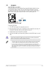
Clear RTC RAM (3-pin CLRTC)

This jumper allows you to clear the Real Time Clock (RTC) RAM in CMOS. You can 

clear the CMOS memory of date, time, and system setup parameters by erasing 

the CMOS RTC RAM data. The onboard button cell battery powers the RAM data in 

CMOS, which include system setup information such as system passwords.

Except when clearing the RTC RAM, never remove the cap on CLRTC jumper default 

position. Removing the cap will cause system boot failure!

•  If the steps above do not help, remove the onboard battery and move the jumper again 

to clear the CMOS RTC RAM data. After clearing the CMOS, reinstall the battery.

•  You do not need to clear the RTC when the system hangs due to overclocking. For 

system failure due to overclocking, use the CPU Parameter Recall (C.P.R.) feature. Shut 

down and reboot the system, then the BIOS automatically resets parameter settings to 

default values.

To erase the RTC RAM:
1.  Turn OFF the computer and unplug the power cord.
2.  Move the jumper cap from pins 1-2 (default) to pins 2-3. Keep the cap on pins 2-3 

for about 5-10 seconds, then move the cap back to pins 1-2.

3.  Plug the power cord and turn ON the computer.
4.  Hold down the <

Del

> key during the boot process and enter BIOS setup to re-enter 

data.

P8H61-M LX

P8H61-M LX Clear RTC RAM

1 2

2 3

Normal

(Default)

Clear RTC

CLRTC

Summary of Contents for P8H61-M LX PLUS R2.0

Page 1: ...Motherboard P8H61 M LX Series P8H61 M LX P8H61 M LX PLUS ...

Page 2: ...anation and to the owners benefit without intent to infringe Offer to Provide Source Code of Certain Software This product may contain copyrighted software that is licensed under the General Public License GPL and under the Lesser General Public License Version LGPL The GPL and LGPL licensed code in this product is distributed without any warranty Copies of these licenses are included in this prod...

Page 3: ...t 1 7 1 5 4 Layout contents 1 7 1 6 Central Processing Unit CPU 1 8 1 6 1 Installing the CPU 1 8 1 6 2 Installing the CPU heatsink and fan 1 11 1 6 3 Uninstalling the CPU heatsink and fan 1 12 1 7 System memory 1 13 1 7 1 Overview 1 13 1 7 2 Memory configurations 1 14 1 7 3 Installing a DIMM 1 17 1 7 4 Removing a DIMM 1 17 1 8 Expansion slots 1 18 1 8 1 Installing an expansion card 1 18 1 8 2 Conf...

Page 4: ...xxxx 2 11 2 3 3 System Time xx xx xx 2 11 2 3 4 Security 2 11 2 4 Ai Tweaker menu 2 13 2 4 1 Memory Frequency Auto 2 13 2 4 2 iGPU Max Frequency Auto 2 13 2 4 3 EPU Power Saving Mode Disabled 2 14 2 4 4 GPU Boost OK 2 14 2 4 5 DRAM Timing Control 2 14 2 4 6 CPU Power Management 2 14 2 4 7 iGPU Offset Mode Sign 2 15 2 4 8 CPU Offset Mode Sign 2 15 2 4 9 DRAM Voltage Auto 2 15 2 4 10 VCCIO Voltage A...

Page 5: ...Voltage 5V Voltage 12V Voltage 2 23 2 6 5 Anti Surge Support Enabled 2 23 2 7 Boot menu 2 24 2 7 1 Bootup NumLock State On 2 24 2 7 2 Full Screen Logo Enabled 2 24 2 7 3 Wait for F1 If Error Enabled 2 24 2 7 4 Option ROM Messages Force BIOS 2 25 2 7 5 Setup Mode EZ Mode 2 25 2 7 6 Boot Option Priorities 2 25 2 7 7 Boot Override 2 25 2 8 Tools menu 2 26 2 8 1 ASUS EZ Flash Utility 2 26 2 8 2 ASUS S...

Page 6: ...g measures Reorient or relocate the receiving antenna Increase the separation between the equipment and receiver Connect the equipment to an outlet on a circuit different from that to which the receiver is connected Consult the dealer or an experienced radio TV technician for help The use of shielded cables for connection of the monitor to the graphics card is required to assure compliance with FC...

Page 7: ...isconnect all power cables from the existing system before you add a device Before connecting or removing signal cables from the motherboard ensure that all power cables are unplugged Seek professional assistance before using an adapter or extension cord These devices could interrupt the grounding circuit Ensure that your power supply is set to the correct voltage in your area If you are not sure ...

Page 8: ...entation such as warranty flyers that may have been added by your dealer These documents are not part of the standard package Typography Bold text Indicates a menu or an item to select Italics Used to emphasize a word or a phrase Key Keys enclosed in the less than and greater than sign means that you must press the enclosed key Example Enter means that you must press the Enter or Return key Key1 K...

Page 9: ...to www asus com for the latest Memory QVL Qualified Vendors List When you install a total memory of 4GB capacity or more Windows 32 bit operating system may only recognize less than 3GB We recommend a maximum of 3GB system memory if you are using a Windows 32 bit operating system Graphics Intel Quick Sync Video Technology Support Supports Microsoft DirectX 10 1 Supports D Sub with max resolution u...

Page 10: ...o jacks support 8 channel Internal connectors switches buttons 3 x USB 2 0 1 1 connectors support additional 6 USB 2 0 1 1 ports 4 x SATA 3 0 Gb s connectors 1 x CPU fan connector 1 x Chassis fan connector 1 x Front panel audio connector 1 x S PDIF Out connector 1 x speaker connector 1 x System panel connector 1 x 24 pin EATX power connector 1 x 4 pin ATX 12V power connector BIOS features 32 Mb Fl...

Page 11: ...sors This motherboard supports the Intel second generation Core i7 Core i5 Core i3 processors in LGA1155 package with memory and PCI Express controllers integrated to support 2 channel 2 DIMMs DDR3 memory and 16 PCI Express 2 0 lanes This provides great graphics performance Intel second generation Core i7 Core i5 Core i3 processors are among the most powerful and energy efficient CPUs in the world...

Page 12: ...at types of peripherals are plugged into the audio I O jacks and notifies users of inappropriate connection which means there will be no more confusion of Line in Line out and Mic jacks Gigabit LAN solution The onboard LAN controller is a highly integrated Gb LAN controller It is enhanced with an ACPI management function to provide efficient power management for advanced operating systems 100 All ...

Page 13: ...n hot airflows generated by the northbridge chipset Combined with usability and aesthetics the ASUS stylish Heatsink will give users an extremely silent and cooling experience with the elegant appearance ESD Protect Your Computer with ESD Guards Electrostatic discharge ESD conditions can happen while plugging or unplugging any USB peripherals causing damage to the computer ASUS ESD Guards clamp th...

Page 14: ...he BIOS C P R feature automatically restores the CPU default settings when the system hangs due to overclocking failure C P R eliminates the need to open the system chassis and clear the RTC data Simply shut down and reboot the system and the BIOS automatically restores the CPU parameters to their default settings ErP ready The motherboard is European Union s Energy related Products ErP ready and ...

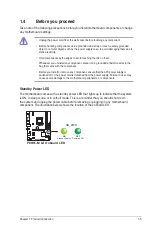
Page 15: ...place it on a grounded antistatic pad or in the bag that came with the component Before you install or remove any component ensure that the ATX power supply is switched off or the power cord is detached from the power supply Failure to do so may cause severe damage to the motherboard peripherals or components Standby Power LED The motherboard comes with a standby power LED that lights up to indica...

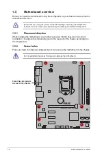
Page 16: ...hysical injury and damage motherboard components 1 5 1 Placement direction When installing the motherboard ensure that you place it into the chassis in the correct orientation The edge with external ports goes to the rear part of the chassis as indicated in the image below 1 5 2 Screw holes Place six screws into the holes indicated by circles to secure the motherboard to the chassis Do not overtig...

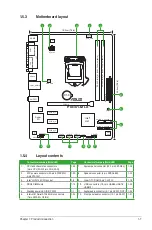
Page 17: ...ors 10 1 pin USB56 USB78 USB910 1 23 5 Standby power LED SB_PWR 1 1 11 Digital audio connector 4 1 pin SPDIF_OUT 1 24 6 Intel H61 Serial ATA 3 0Gb s connectors 7 pin SATA3G_1 2 3 4 1 24 12 Front panel audio connector 10 1 pin AAFP 1 21 P8H61 M LX PCIEX16 PCIEX1_1 PCIEX1_2 PCIEX1_3 F_PANEL SPEAKER CLRTC AAFP ATX12V EATXPWR CPU_FAN CHA_FAN Lithium Cell CMOS Power Super I O ALC 887 RTL 8111E EPU 32Mb...

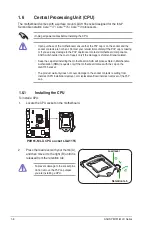
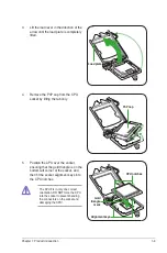
Page 18: ...amage is shipment transit related Keep the cap after installing the motherboard ASUS will process Return Merchandise Authorization RMA requests only if the motherboard comes with the cap on the LGA1155 socket The product warranty does not cover damage to the socket contacts resulting from incorrect CPU installation removal or misplacement loss incorrect removal of the PnP cap 1 6 1 Installing the ...

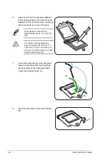
Page 19: ...ng the tab only The CPU fits in only one correct orientation DO NOT force the CPU into the socket to prevent bending the connectors on the socket and damaging the CPU Gold triangle mark Alignment keys CPU notches 5 Position the CPU over the socket ensuring that the gold triangle is on the bottom left corner of the socket and then fit the socket alignment keys into the CPU notches PnP cap ...

Page 20: ...ntion tab 6 Apply some Thermal Interface Material to the exposed area of the CPU that the heatsink will be in contact with ensuring that it is spread in an even thin layer Some heatsinks come with pre applied thermal paste If so skip this step The Thermal Interface Material is toxic and inedible DO NOT eat it If it gets into your eyes or touches your skin wash it off immediately and seek professio...

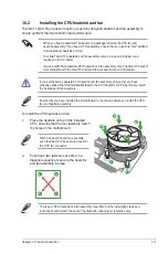
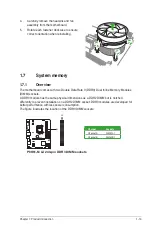
Page 21: ...nsion Ensure that you have installed the motherboard to the chassis before you install the CPU fan and heatsink assembly The type of CPU heatsink and fan assembly may differ but the installation steps and functions should remain the same The illustration above is for reference only To install the CPU heatsink and fan 1 Place the heatsink on top of the installed CPU ensuring that the four fasteners...

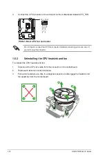
Page 22: ...nector 1 6 3 Uninstalling the CPU heatsink and fan To uninstall the CPU heatsink and fan 1 Disconnect the CPU fan cable from the connector on the motherboard 2 Rotate each fastener counterclockwise 3 Pull up two fasteners at a time in a diagonal sequence to disengage the heatsink and fan assembly from the motherboard A A B B A A B B CPU_FAN CPU FAN PWM CPU FAN IN CPU FAN PWR GND P8H61 M LX P8H61 M...

Page 23: ...ame physical dimensions as a DDR2 DIMM but is notched differently to prevent installation on a DDR2 DIMM socket DDR3 modules are developed for better performance with less power consumption The figure illustrates the location of the DDR3 DIMM sockets 4 Carefully remove the heatsink and fan assembly from the motherboard 5 Rotate each fastener clockwise to ensure correct orientation when reinstallin...

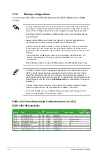
Page 24: ...otect the CPU Always install DIMMs with the same CAS latency For optimum compatibility we recommend that you obtain memory modules from the same vendor Due to the memory address limitation on 32 bit Windows OS when you install 4GB or more memory on the motherboard the actual usable memory for the OS can be about 3GB or less For effective use of memory we recommend that you do any of the following ...

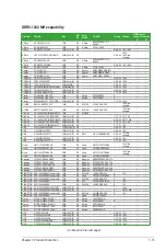
Page 25: ...9QC 16GB 4 x 4GB DS 9 9 9 24 1 5V GEIL GV32GB1333C9DC 2GB 2 x 1GB DS 9 9 9 24 1 5V GEIL GG34GB1333C9DC 4GB 2 x 2GB DS GEIL GL1L128M88BA12N 9 9 9 24 1 3V low voltage GEIL GV34GB1333C9DC 4GB 2 x 2GB DS 9 9 9 24 1 5V GEIL GVP34GB1333C7DC 4GB 2 x 2GB DS 7 7 7 24 1 5V Hynix HMT112U6TFR8A H9 1GB SS Hynix H5TC1G83TFRH9A 1 35V low voltage Hynix HMT325U6BFR8C H9 2GB SS Hynix H5TQ2G83BFRH9C Hynix HMT125U6TF...

Page 26: ...65V OCZ OCZ3X1333LV6GK XMP 6GB 3 x 2GB DS 8 8 8 20 1 60V OCZ OCZ3G1333LV8GK 8GB 2x 4GB DS 9 9 9 20 1 65V OCZ OCZ3RPR1333C9LV8GK 8GB 2x 4GB DS 9 9 9 20 1 65V PSC AL7F8G73F DJ2 1GB SS PSC A3P1GF3FGF PSC AL8F8G73F DJ2 2GB DS PSC A3P1GF3FGF SAMSUNG M378B2873FHS CH9 1GB SS SAMSUNG K4B1G0846F SAMSUNG M378B5673FH0 CH9 2GB DS SAMSUNG K4B1G0846F SAMSUNG M378B5273CH0 CH9 4GB DS SAMSUNG K4B2G0846C Super Tale...

Page 27: ...MM notch 2 1 A DIMM is keyed with a notch so that it fits in only one direction DO NOT force a DIMM into a socket in the wrong direction to avoid damaging the DIMM 3 Firmly insert the DIMM into the socket until the retaining clips snap back in place and the DIMM is properly seated Locked Retaining Clip 3 1 7 4 Removing a DIMM To remove a DIMM 1 Simultaneously press the retaining clips outward to u...

Page 28: ...seated on the slot 5 Secure the card to the chassis with the screw you removed earlier 6 Replace the system cover 1 8 2 Configuring an expansion card After installing the expansion card configure it by adjusting the software settings 1 Turn on the system and change the necessary BIOS settings if any See Chapter 2 for information on BIOS setup 2 Assign an IRQ to the card 3 Install the software driv...

Page 29: ... the jumper again to clear the CMOS RTC RAM data After clearing the CMOS reinstall the battery You do not need to clear the RTC when the system hangs due to overclocking For system failure due to overclocking use the CPU Parameter Recall C P R feature Shut down and reboot the system then the BIOS automatically resets parameter settings to default values To erase the RTC RAM 1 Turn OFF the computer...

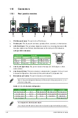
Page 30: ... Front Speaker Out 6 Microphone port pink This port connects to a microphone Activity Link LED Speed LED Status Description Status Description OFF No link OFF 10Mbps connection ORANGE Linked ORANGE 100Mbps connection BLINKING Data activity GREEN 1Gbps connection Refer to the audio configuration table below for the function of the audio ports in 2 4 6 or 8 channel configuration Audio 2 4 6 or 8 cha...

Page 31: ...gacy AC 97 audio standard Connect one end of the front panel audio I O module cable to this connector We recommend that you connect a high definition front panel audio module to this connector to avail of the motherboard s high definition audio capability If you want to connect a high definition front panel audio module to this connector set the Front Panel Type item in the BIOS setup to HD If you...

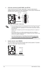
Page 32: ...rt asus com PowerSupplyCalculator PSCalculator aspx SLanguage en us for details 2 ATX power connectors 24 pin EATXPWR 4 pin ATX12V These connectors are for ATX power supply plugs The power supply plugs are designed to fit these connectors in only one orientation Find the proper orientation and push down firmly until the connectors completely fit P8H61 M LX P8H61 M LX ATX power connectors EATXPWR P...

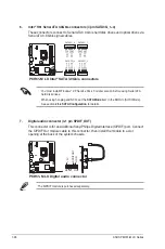
Page 33: ...CPU FAN PWM CPU FAN IN CPU FAN PWR GND Rotation 12V GND P8H61 M LX P8H61 M LX CPU connectors CHA_FAN 5 USB connectors 10 1 pin USB56 USB78 USB910 These connectors are for USB 2 0 ports Connect the USB module cable to any of these connectors then install the module to a slot opening at the back of the system chassis These USB connectors comply with USB 2 0 specification that supports up to 480 Mbps...

Page 34: ...P2 RSATA_TXN2 GND RSATA_RXP2 RSATA_RXN2 GND GND RSATA_RXN4 RSATA_RXP4 GND RSATA_TXN4 RSATA_TXP4 GND SATA3G_4 SATA3G_1 GND RSATA_TXP1 RSATA_TXN1 GND RSATA_RXP1 RSATA_RXN1 GND GND RSATA_RXN3 RSATA_RXP3 GND RSATA_TXN3 RSATA_TXP3 GND SATA3G_3 P8H61 M LX P8H61 M LX Intel SATA 3 0Gb s connectors 7 Digital audio connector 4 1 pin SPDIF_OUT This connector is for an additional Sony Philips Digital Interfac...

Page 35: ...d disk drive activity LED 2 pin HDLED This 2 pin connector is for the HDD Activity LED Connect the HDD Activity LED cable to this connector The IDE LED lights up or flashes when data is read from or written to the HDD Power Soft off button 2 pin PWRBTN This 2 pin connector is for the system power button Reset button 2 pin RESET This 2 pin connector is for the chassis mounted reset button for syste...

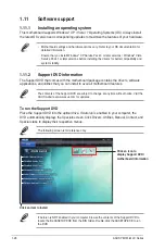
Page 36: ...e motherboard package contains the drivers software applications and utilities that you can install to avail all motherboard features If Autorun is NOT enabled in your computer browse the contents of the Support DVD to locate the file ASSETUP EXE from the BIN folder Double click the ASSETUP EXE to run the DVD The following screen is for reference only The contents of the Support DVD are subject to...

Page 37: ... and then click ASUS Update from the popup menu The ASUS Update main screen appears From the list select either of the following methods Updating from the Internet a Select Update BIOS from the Internet then click Next b Select the ASUS FTP site nearest you to avoid network traffic then click Next c From the FTP site select the BIOS version that you wish to download then click Next 2 1 1 ASUS Upda...

Page 38: ...tility and press Enter to enable it The ASUS Update utility is capable of updating itself through the Internet Always update the utility to avail all its features Updating from a BIOS file a Select Update BIOS from file then click Next b Locate the BIOS file from the Open window then click Open 3 Follow the onscreen instructions to complete the updating process Flash Info MODEL P8H61 M LX VER 0206...

Page 39: ...he utility reads the BIOS file and enters ASUS EZ Flash 2 utility automatically 4 The system requires you to enter BIOS Setup to recover BIOS setting To ensure system compatibility and stability we recommend that you press F5 to load default BIOS values DO NOT shut down or reset the system while updating the BIOS Doing so can cause system boot failure 3 Press Tab to switch to the Drive field 4 Pre...

Page 40: ...g process The succeeding utility screens are for reference only The actual utility screen displays may not be same as shown Before updating BIOS 1 Prepare the motherboard support DVD and a USB flash drive in FAT32 16 format and single partition 2 Download the latest BIOS file and BIOS Updater from the ASUS website at http support asus com and save them on the USB flash drive NTFS is not supported ...

Page 41: ...SB flash drive is not write protected and has at least 4MB free space to save the file 1 At the FreeDOS prompt type bupdater o filename and press Enter The filename is any user assigned filename with no more than eight alphanumeric characters for the filename and three alphanumeric characters for the extension ASUSTek BIOS Updater for DOS V1 18 Current ROM Update ROM Note Saving BIOS PATH A BOARD ...

Page 42: ...d keys to select the BIOS file and press Enter BIOS Updater checks the selected BIOS file and prompts you to confirm BIOS update Are you sure to update BIOS Yes No 4 Select Yes and press Enter When BIOS update is done press ESC to exit BIOS Updater Restart your computer DO NOT shut down or reset the system while updating the BIOS to prevent system boot failure For BIOS Updater version 1 04 or late...

Page 43: ...the Load Optimized Defaults item under the Exit menu See section 2 9 Exit Menu for details If the system fails to boot after changing any BIOS setting try to clear the CMOS and reset the motherboard to the default value See section 1 9 Jumpers for information on how to erase the RTC RAM 2 2 BIOS setup program Use the BIOS Setup program to update the BIOS or configure its parameters The BIOS screen...

Page 44: ...d to the system P8H61 M LX BIOS Version 0206 Build Date 05 16 2011 CPU Type Intel R Core TM i5 2400 CPU 3 10GHz Speed 3100 MHz Total Memory 1024 MB DDR3 1333MHz Exit Advanced Mode Temperature Voltage Fan Speed CPU 113 0ºF 45 0ºC CPU 1 248V 5V 5 160V CPU_FAN 3325RPM CHA_FAN N A MB 75 2ºF 40 0ºC 3 3V 3 344V 12V 12 248V English EFI BIOS Utility EZ Mode Friday 10 08 2010 Normal Boot Menu F8 Default F5...

Page 45: ...EFI BIOS Utility Advanced Mode Menu bar The menu bar on top of the screen has the following main items Main For changing the basic system configuration Ai Tweaker For changing the overclocking settings Advanced For changing the advanced system settings Monitor For displaying the system temperature power status and changing the fan settings Boot For changing the system boot configuration Tool For c...

Page 46: ...uration options for that item Scroll bar A scroll bar appears on the right side of a menu screen when there are items that do not fit on the screen Press the Up Down arrow keys or Page Up Page Down keys to display the other items on the screen Navigation keys At the bottom right corner of the menu screen are the navigation keys for the BIOS setup program Use the navigation keys to select items in ...

Page 47: ... security settings If you have forgotten your BIOS password erase the CMOS Real Time Clock RTC RAM to clear the BIOS password See section 1 9 Jumpers for information on how to erase the RTC RAM The Administrator or User Password items on top of the screen show the default Not Installed After you set a password these items show Installed Main Ai Tweaker Advanced Monitor Boot Tool Exit EFI BIOS Util...

Page 48: ...ter when prompted to create confirm the password After you clear the password the Administrator Password item on top of the screen shows Not Installed User Password If you have set a user password you must enter the user password for accessing the system The User Password item on top of the screen shows the default Not Installed After you set a password this item shows Installed To set a user pass...

Page 49: ...tility Advanced Mode Target DRAM Speed xxxxMHz Displays the current DRAM speed 2 4 1 Memory Frequency Auto Allows you to set the memory operating frequency Configuration options DDR3 800MHz DDR3 1066MHz DDR3 1333MHz Selecting a very high memory frequency may cause the system to become unstable If this happens revert to the default setting 2 4 2 iGPU Max Frequency Auto Auto The iGPU frequency may b...

Page 50: ...le If this happens revert to the default settings 2 4 6 CPU Power Management The sub items in this menu allow you to set the CPU ratio and features CPU Ratio Auto Allows you to manually adjust the maximum non turbo CPU ratio Use and keys or the numeric keypad to adjust the ratio The valid value ranges vary according to your CPU model Enhanced Intel SpeedStep Technology Enabled Allows you to enable...

Page 51: ...e CPU Voltage Auto Allows you to set the Offset voltage The values range from 0 310V to 0 630V with a 0 010V interval Refer to the CPU documentation before setting the CPU voltage Setting a high voltage may damage the CPU permanently and setting a low voltage may make the system unstable 2 4 9 DRAM Voltage Auto Allows you to set the DRAM voltage The values range from 1 185V to 2 135V with a 0 005V...

Page 52: ...SC Exit F12 Print Screen CPU Configuration System Agent Configuration PCH Configuration SATA Configuration USB Configuration Onboard Devices Configuration APM 2 5 1 CPU Configuration The items in this menu show the CPU related information that the BIOS automatically detects The items shown in submenu may be different due to the CPU you installed 2 4 12 PCH Voltage Auto Allows you to set the Platfo...

Page 53: ...rtualization Technology Disabled Enabled Allows a hardware platform to run multiple operating systems separately and simultaneously enabling one system to virtually function as several systems Disabled Disables this function Enhanced Intel SpeedStep Technology Enabled Allows you to enable or disable the Enhanced Intel SpeedStep Technology EIST Disabled The CPU runs at its default speed Enabled The...

Page 54: ...t items show Not Present if no SATA device is installed to the corresponding SATA port SATA Mode IDE Mode Allows you to set the SATA configuration Disabled Disables the SATA function IDE Mode Set to IDE Mode when you want to use the Serial ATA hard disk drives as Parallel ATA physical storage devices AHCI Mode Set to AHCI Mode when you want the SATA hard disk drives to use the AHCI Advanced Host C...

Page 55: ...led If no USB device is detected the legacy USB support is disabled EHCI Hand off Disabled Enabled Enables the support for operating systems without an EHCI hand off feature Disabled Disables the function 2 5 6 Onboard Devices Configuration HD Audio Controller Enabled Enabled Enables the High Definition Audio Controller Disabled Disables the controller The following two items appear only when you ...

Page 56: ...IO 378h IRQ 5 6 7 9 10 11 12 IO 278h IRQ 5 6 7 9 10 11 12 IO 3BCh IRQ 5 6 7 9 10 11 12 Device Mode STD Printer Mode Allows you to select the Printer Port mode Configuration options STD Printer Mode SPP Mode EPP 1 9 and SPP Mode EPP 1 7 and SPP Mode ECP Mode ECP and EPP 1 9 Mode ECP and EPP 1 7 Mode 2 5 7 APM Restore AC Power Loss Power Off Power On The system goes into on state after an AC power l...

Page 57: ...ices to generate a wake event Power On By Ring Disabled Disabled Disables Ring to generate a wake event Enabled Enables Ring to generate a wake event Power On By RTC Disabled Disabled Disables RTC to generate a wake event Enabled When set to Enabled the items RTC Alarm Date Days and Hour Minute Second will become user configurable with set values ...

Page 58: ...tem appears only when you enable the CPU Q Fan Control feature and allows you to disable or set the CPU fan warning speed Configuration options Ignore 200 RPM 300 RPM 400 RPM 500 RPM 600 RPM CPU Fan Profile Standard This item appears only when you enable the CPU Q Fan Control feature and allows you to set the appropriate performance level of the CPU fan Standard Sets to Standard to make the CPU fa...

Page 59: ...re reaches the upper limit the CPU fan will operate at the maximum duty cycle CPU Lower Temperature 20 Use the and keys to adjust the lower limit of the CPU temperature The values range from 20ºC to 75ºC CPU Fan Min Duty Cycle 20 Use the and keys to adjust the minimum CPU fan duty cycle The values range from 0 to 100 When the CPU temperature is under the lower limit the CPU fan will operate at the...

Page 60: ...5 sec 6 sec 7 sec 8 sec 9 sec 10 sec Until Press ESC 2 7 3 Wait for F1 If Error Enabled When this item is set to Enabled the system waits for the F1 key to be pressed when error occurs Configuration options Disabled Enabled Main Ai Tweaker Advanced Monitor Boot Tool Exit Version 2 00 1201 Copyright C 2010 American Megatrends Inc Select the keyboard NumLock state Select Screen Select Item Enter Sel...

Page 61: ... default screen for entering the BIOS setup program 2 7 6 Boot Option Priorities These items specify the boot device priority sequence from the available devices The number of device items that appears on the screen depends on the number of devices installed in the system To select the boot device during system startup press F8 when ASUS Logo appears To access Windows OS in Safe Mode press F8 afte...

Page 62: ...options Slot 1 Slot 2 2 8 3 ASUS O C Profile This item allows you to store or load multiple BIOS settings The Setup Profile Status items show Not Installed if no profile is created DO NOT shut down or reset the system while updating the BIOS to prevent the system boot failure We recommend that you update the BIOS file only coming from the same memory CPU configuration and BIOS version Save to Prof...

Page 63: ...the Exit menu to ensure the values you selected are saved When you select this option or if you press F10 a confirmation window appears Select Yes to save changes and exit Discard Changes Exit This option allows you to exit the Setup program without saving your changes When you select this option or if you press Esc a confirmation window appears Select Yes to discard changes and exit ASUS EZ Mode ...

Page 64: ...2 28 ASUS P8H61 M LX Series ...

Page 65: ...510 739 3777 Fax 1 510 608 4555 Web site usa asus com Technical Support Telephone 1 812 282 2787 Support fax 1 812 284 0883 Online support support asus com ASUS COMPUTER GmbH Germany and Austria Address Harkort Str 21 23 D 40880 Ratingen Germany Fax 49 2102 959911 Web site www asus de Online contact www asus de sales Technical Support Telephone Component 49 1805 010923 Telephone System Notebook Ee...

Page 66: ... V1 3 1 2007 09 EN 301 357 2 V1 3 1 2006 05 EN 302 623 V1 1 1 2009 01 2006 95 EC LVD Directive EN 60950 1 2006 EN 60950 1 2006 A11 2009 EN 60065 2002 A1 2006 A11 2008 2009 125 EC ErP Directive Regulation EC No 1275 2008 EN 62301 2005 Regulation EC No 642 2009 EN 62301 2005 Regulation EC No 278 2009 EN 62301 2005 Ver 110101 CE marking Declaration Date Jul 27 2011 Year to begin affixing CE marking 2...

Reviews: