


ASUS P7P55 WS Supercomputer
3-15
3.4
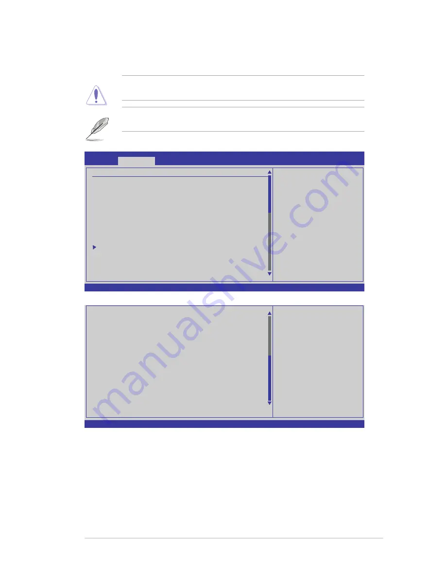
Ai Tweaker menu
The Ai Tweaker menu items allow you to configure overclocking�related items.
Take caution when changing the settings of the
Ai Tweaker
menu items.
Incorrect field values can cause the system to malfunction.
The default values of the following items vary depending on the CPU and
memory modules you install on the motherboard.
v02.61 (C)Copyright 1985-2009, American Megatrends, Inc.
BIOS SETUP UTILITY
Main
AI Tweaker
Advanced Power Boot Tools Exit
[D.O.C.P.]
It’s designed to
overclock DRAM
frequency by adjusting
BCLK frequency.
[X.M.P.]
When X.M.P. is enabled
BLCK frequency, CPU
ratio and memory
parameters will be
auto optimized.
←→
Select Screen
↑↓
Select Item
+- Change Field
F1 General Help
F10 Save and Exit
ESC Exit
Configure System Performance Settings
Ai Overclock Tuner
[Auto]
Ratio CMOS Setting
[Auto]
Intel(R) SpeedStep(TM) Tech [Enabled]
Intel(R) TurboMode Tech
[Enabled]
TurboMode Prevention
[Auto]
Xtreme Phase Full Power Mode [Auto]
DRAM Frequency
[Auto]
QPI Frequency
[Auto]
OC Tuner Utility
OC Tuner limit Value
[Good Performance]
DRAM Timing Control
CPU Differential Amplitude
[Auto]
CPU Clock Skew
[Auto]
******* Please key in numbers directly! *******
CPU Voltage Mode
[Offset]
v02.61 (C)Copyright 1985-2009, American Megatrends, Inc.
←→
Select Screen
↑↓
Select Item
+- Change Option
F1 General Help
F10 Save and Exit
ESC Exit
Offset Voltage
[Auto]
Current CPU Core Voltage
[ 1.048V]
IMC Voltage
[Auto]
Current IMC Voltage
[ 1.109V]
DRAM Voltage
[Auto]
Current DRAM Voltage
[ 1.500V]
CPU PLL Voltage
[Auto]
Current CPU PLL Voltage
[ 1.800V]
PCH Voltage
[Auto]
Current PCH Voltage
[ 1.040V]
DRAM DATA REF Voltage on CHA [Auto]
DRAM CTRL REF Voltage on CHA [Auto]
DRAM DATA REF Voltage on CHB [Auto]
DRAM CTRL REF Voltage on CHB [Auto]
***********************************************
Load-Line Calibration
[Auto]
CPU Spread Spectrum
[Auto]
PCIE Spread Spectrum
[Auto]
Scroll down to display the following items:


