background image

A S U S   P 5 R D 1 - V   D e l u x e

A S U S   P 5 R D 1 - V   D e l u x e

A S U S   P 5 R D 1 - V   D e l u x e

A S U S   P 5 R D 1 - V   D e l u x e

A S U S   P 5 R D 1 - V   D e l u x e

4 - 2 9

4 - 2 9

4 - 2 9

4 - 2 9

4 - 2 9

4.4.6

4.4.6

4.4.6

4.4.6

4.4.6

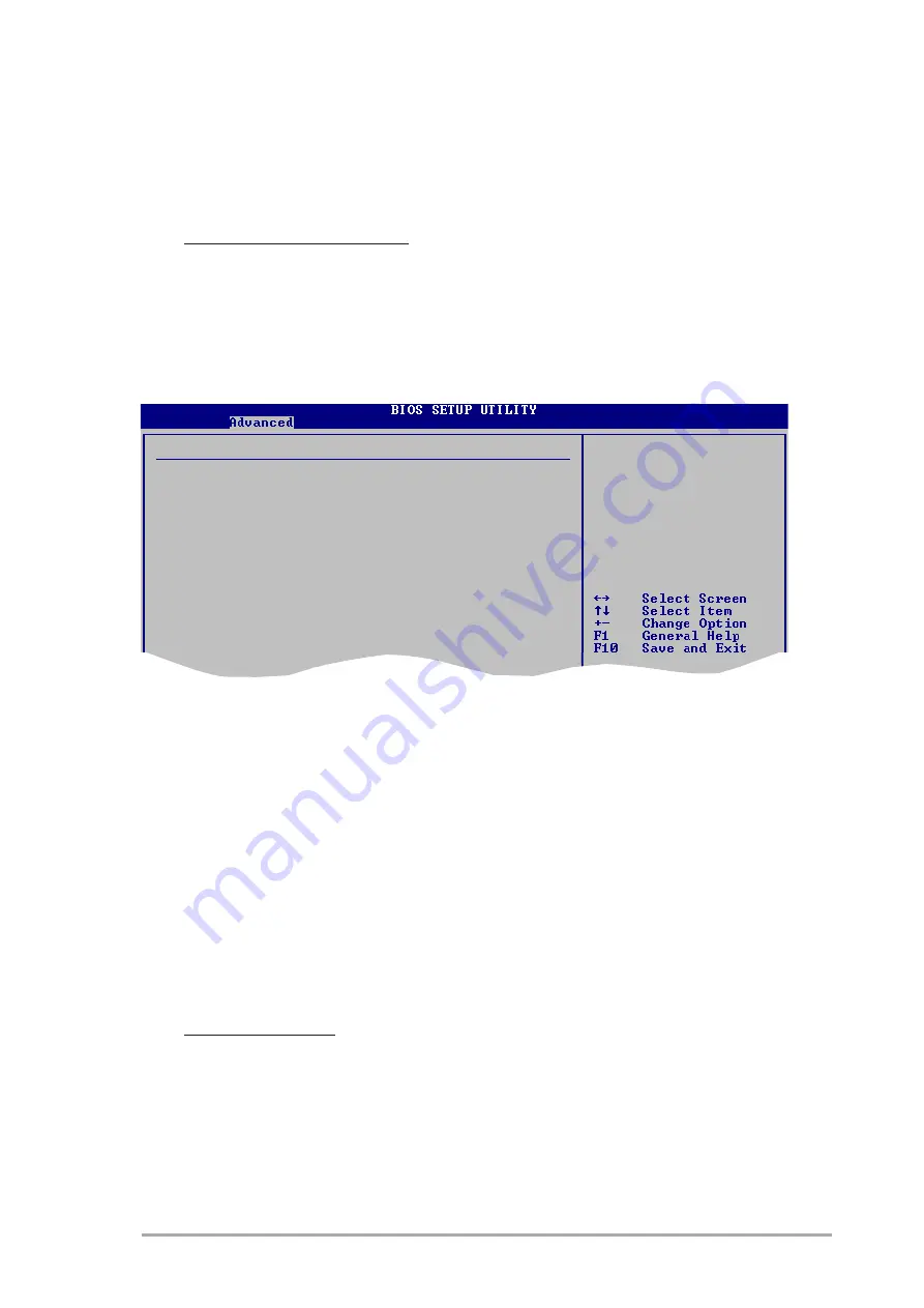
Onboard Devices Configuration

Onboard Devices Configuration

Onboard Devices Configuration

Onboard Devices Configuration

Onboard Devices Configuration

Configure ITE8712 Super IO Chipset

Serial Port1 Address

[3F8/IRQ4]

Parallel Port Address

[378]

Parallel Port Mode

[ECP]

EPP Version

[1.9]

  Parallel Port IRQ

[IRQ7]

Onboard Game Port

[Enabled]

Onboard MIDI Port

[330]

MIDI IRQ Select

[IRQ5]

Serial Port1 Address [3F8/IRQ4]

Serial Port1 Address [3F8/IRQ4]

Serial Port1 Address [3F8/IRQ4]

Serial Port1 Address [3F8/IRQ4]

Serial Port1 Address [3F8/IRQ4]

Allows you to select the Serial Port1 base address.
Configuration options: [Disabled] [3F8/IRQ4] [2F8/IRQ3] [3E8/IRQ4]
[2E8/IRQ3]

Parallel Port Address [378]

Parallel Port Address [378]

Parallel Port Address [378]

Parallel Port Address [378]

Parallel Port Address [378]

Allows you to select the Parallel Port base addresses.
Configuration options: [Disabled] [378] [278] [3BC]

Parallel Port Mode [EPP]

Parallel Port Mode [EPP]

Parallel Port Mode [EPP]

Parallel Port Mode [EPP]

Parallel Port Mode [EPP]

Allows you to select the Parallel Port  mode.
Configuration options: [Normal] [EPP] [ECP] [ECP+EPP]

EPP Version [1.9]

Allows you to select the parallel port EPP  version. This item becomes
configurable only if the P a r a l l e l   P o r t   M o d e

P a r a l l e l   P o r t   M o d e

P a r a l l e l   P o r t   M o d e

P a r a l l e l   P o r t   M o d e

P a r a l l e l   P o r t   M o d e is set to [EPP] or

[ECP+EPP]. Configuration options: [1.9] [1.7]

Enable or disable the
Azalia controller.

O n B o a r d   L A N   B o o t   R O M   [ D i s a b l e d ]

O n B o a r d   L A N   B o o t   R O M   [ D i s a b l e d ]

O n B o a r d   L A N   B o o t   R O M   [ D i s a b l e d ]

O n B o a r d   L A N   B o o t   R O M   [ D i s a b l e d ]

O n B o a r d   L A N   B o o t   R O M   [ D i s a b l e d ]

Allows you to enable or disable the onboard LAN boot ROM.
Configuration options: [Disabled] [Enabled]

Philips TV Tuner [Enabled]

Allows you to enable or disable the Philips TV tuner.
Configuration options: [Enabled] [Disabled]

Summary of Contents for P5RD1-V Deluxe

Page 1: ...Motherboard P5RD1 V Deluxe ...

Page 2: ...OR CONDITIONS OF MERCHANTABILITY OR FITNESS FOR A PARTICULAR PURPOSE IN NO EVENT SHALL ASUS ITS DIRECTORS OFFICERS EMPLOYEES OR AGENTS BE LIABLE FOR ANY INDIRECT SPECIAL INCIDENTAL OR CONSEQUENTIAL DAMAGES INCLUDING DAMAGES FOR LOSS OF PROFITS LOSS OF BUSINESS LOSS OF USE OR DATA INTERRUPTION OF BUSINESS AND THE LIKE EVEN IF ASUS HAS BEEN ADVISED OF THE POSSIBILITY OF SUCH DAMAGES ARISING FROM ANY...

Page 3: ...ation Hardware information Hardware information Hardware information 2 1 Before you proceed 2 1 2 2 Motherboard overview 2 2 2 2 1 Placement direction 2 2 2 2 2 Screw holes 2 2 2 2 3 Motherboard layout 2 3 2 2 4 Layout Contents 2 4 2 3 Central Processing Unit CPU 2 6 2 3 1 Installing the CPU 2 6 2 3 2 Installing the CPU heatsink and fan 2 9 2 3 3 Uninstalling the CPU heatsink and fan 2 11 2 4 Syst...

Page 4: ...up BIOS setup BIOS setup BIOS setup 4 1 Managing and updating your BIOS 4 1 4 1 1 Creating a bootable floppy disk 4 1 4 1 2 AFUDOS utility 4 2 4 1 3 ASUS EZ Flash utility 4 5 4 1 4 ASUS CrashFree BIOS 2 utility 4 6 4 1 5 ASUS Update utility 4 8 4 2 BIOS setup program 4 11 4 2 1 BIOS menu screen 4 12 4 2 2 Menu bar 4 12 4 2 3 Navigation keys 4 12 4 2 4 Menu items 4 13 4 2 5 Sub menu items 4 13 4 2 ...

Page 5: ...nu 4 37 4 6 1 Boot Device Priority 4 37 4 6 2 Boot Settings Configuration 4 38 4 6 3 Security 4 39 4 7 Exit menu 4 41 Chapter 5 Chapter 5 Chapter 5 Chapter 5 Chapter 5 Software support Software support Software support Software support Software support 5 1 Installing an operating system 5 1 5 2 Support CD information 5 1 5 2 1 Running the support CD 5 1 5 2 2 Drivers menu 5 2 5 2 3 Utilities menu ...

Page 6: ...sk 5 42 Appendix Appendix Appendix Appendix Appendix Reference information Reference information Reference information Reference information Reference information A 1 Enhanced Intel SpeedStep Technology EIST 5 1 A 1 1 System requirements 5 1 A 1 2 Using the EIST 5 1 A 2 Intel Hyper Threading Technology 5 3 A 3 Remote controller specifications 5 4 A 4 Using the remote controller 5 4 A 5 Remote cont...

Page 7: ...e user is encouraged to try to correct the interference by one or more of the following measures Reorient or relocate the receiving antenna Increase the separation between the equipment and receiver Connect the equipment to an outlet on a circuit different from that to which the receiver is connected Consult the dealer or an experienced radio TV technician for help Canadian Department of Communica...

Page 8: ... correct voltage in your area If you are not sure about the voltage of the electrical outlet you are using contact your local power company If the power supply is broken do not try to fix it by yourself Contact a qualified service technician or your retailer Operation safety Operation safety Operation safety Operation safety Operation safety Before installing the motherboard and adding devices on ...

Page 9: ... system settings through the BIOS Setup menus Detailed descriptions of the BIOS parameters are also provided Chapter 5 Software support Chapter 5 Software support Chapter 5 Software support Chapter 5 Software support Chapter 5 Software support This chapter describes the contents of the support CD that comes with the motherboard package Appendix Reference information Appendix Reference information ...

Page 10: ...lp you complete a task IMPORTANT IMPORTANT IMPORTANT IMPORTANT IMPORTANT Instructions that you MUST follow to complete a task Typography Typography Typography Typography Typography Bold text Bold text Bold text Bold text Bold text Indicates a menu or an item to select Italics Used to emphasize a word or a phrase Key Keys enclosed in the less than and greater than sign means that you must press the...

Page 11: ...sor Compatible with Intel PCG 04A and O4B processors Supports Intel FMB 1 5 specification Supports Intel Hyper Threading Technology Supports Enhanced Intel SpeedStep Technology EIST Northbridge ATI Radeon XPRESS 200 Southbridge ULI M1573 800 533 MHz Dual channel memory architecture 4 x 184 pin DIMM sockets support unbufferred non ECC 400 333 266 MHz DDR memory modules 1 x PCI Express x16 slot for ...

Page 12: ... x Chassis fan connector 1 x Power fan connector 1 x Serial port connector 2 x USB 2 0 connectors for four additional USB 2 0 ports 1 x 24 pin ATX power connector 1 x 4 pin ATX 12 V power connector 1 x IEEE 1394a connector 1 x GAME MIDI connector 1 x MIDI connector 1 x Front panel audio connector 1 x S PDIF out connector 1 x Capture in connector 1 x TV out connector 1 x System panel connector P5RD...

Page 13: ... x 9 6 in 30 5 cm x 24 4 cm P5RD1 V Deluxe specifications summary Support CD Support CD Support CD Support CD Support CD contents contents contents contents contents Form factor Form factor Form factor Form factor Form factor Specifications are subject to change without notice Due to chipset limitation you cannot configure a RAID 0 JBOD set across more than two hard disk drives ...

Page 14: ...x i v x i v x i v x i v x i v ...

Page 15: ...1 Product introduction This chapter describes the motherboard features and the new technologies it supports ...

Page 16: ...ASUS P5RD1 V Deluxe ASUS P5RD1 V Deluxe ASUS P5RD1 V Deluxe ASUS P5RD1 V Deluxe ASUS P5RD1 V Deluxe Chapter summary 1 1 1 Welcome 1 1 1 2 Package contents 1 1 1 3 Special features 1 2 ...

Page 17: ...2 Package contents Check your motherboard package for the following items Motherboard Motherboard Motherboard Motherboard Motherboard ASUS P5RD1 V Deluxe motherboard I O modules I O modules I O modules I O modules I O modules 1 x TV out capture in module 1 x Serial port module 1 x IEEE 1394a 1 port module 1 x USB 2 0 2 ports and Game 1 port module Cables Cables Cables Cables Cables 1 x 4 in 1 Flop...

Page 18: ... processor in the 775 land package with 533 800 MHz front side bus FSB dual channel DDR memory three PCI Express x1 slots and a PCI Express x16 slot for discrete graphics card The ULI M1573 Southbridge represents the sixth generation I O controller hub that provides the interface for PCI Express and 8 channel high definition audio Enhanced Intel SpeedStep Enhanced Intel SpeedStep Enhanced Intel Sp...

Page 19: ...ount reduced voltage requirement and up to 150 MB s data transfer rate See page 2 28 for details SATA RAID solution SATA RAID solution SATA RAID solution SATA RAID solution SATA RAID solution Onboard RAID controllers provide the motherboard with RAID functionality The ULI M1573 Southbridge allows RAID 0 RAID 1 RAID 0 1 and JBOD configuration See page 5 35 for details Gigabit LAN Gigabit LAN Gigabi...

Page 20: ...erclocking System AI NOS Non Delay Overclocking System ASUS Non delay Overclocking System NOS is a technology that auto detects the CPU loading and dynamically overclocks the CPU speed only when needed See pages 4 20 and 4 22 for details AI NET2 AI NET2 AI NET2 AI NET2 AI NET2 The AI NET2 is a BIOS based diagnostic tool that detects and reports Ethernet cable faults and shorts With this utility yo...

Page 21: ...uy a replacement ROM chip See page 4 6 for details ASUS MyLogo 2 ASUS MyLogo 2 ASUS MyLogo 2 ASUS MyLogo 2 ASUS MyLogo 2 This feature allows you to personalize and add style to your system with customizable boot logos See page 5 7 for details C P R CPU Parameter Recall C P R CPU Parameter Recall C P R CPU Parameter Recall C P R CPU Parameter Recall C P R CPU Parameter Recall The C P R feature of t...

Page 22: ...1 6 1 6 1 6 1 6 1 6 Chapter 1 Product introduction Chapter 1 Product introduction Chapter 1 Product introduction Chapter 1 Product introduction Chapter 1 Product introduction ...

Page 23: ... Hardware information This chapter lists the hardware setup procedures that you have to perform when installing system components It includes description of the jumpers and connectors on the motherboard ...

Page 24: ...5RD1 V Deluxe ASUS P5RD1 V Deluxe ASUS P5RD1 V Deluxe Chapter summary 2 2 1 Before you proceed 2 1 2 2 Motherboard overview 2 2 2 3 Central Processing Unit CPU 2 6 2 4 System memory 2 13 2 5 Expansion slots 2 18 2 6 Jumpers 2 21 2 7 Connectors 2 24 ...

Page 25: ...e to static electricity Hold components by the edges to avoid touching the ICs on them Whenever you uninstall any component place it on a grounded antistatic pad or in the bag that came with the component Before you install or remove any component ensure Before you install or remove any component ensure Before you install or remove any component ensure Before you install or remove any component en...

Page 26: ...ing so can damage the motherboard 2 2 1 2 2 1 2 2 1 2 2 1 2 2 1 Placement direction Placement direction Placement direction Placement direction Placement direction When installing the motherboard make sure that you place it into the chassis in the correct orientation The edge with external ports goes to the rear part of the chassis as indicated in the image below 2 2 2 2 2 2 2 2 2 2 2 2 2 2 2 Scre...

Page 27: ...USB34 COM1 DDR DIMM_A1 64 bit 184 pin module CPU_FAN LGA775 Below Center Subwoofer Center Side Speaker Out Top Rear Speaker Out 24 5cm 9 6in 30 5cm 12 0in DDR DIMM_A2 64 bit 184 pin module DDR DIMM_B1 64 bit 184 pin module DDR DIMM_B2 64 bit 184 pin module PCIEX1_1 PCIEX1_2 PCIEX1_3 PCIEX16 PCI1 PCI2 PCI3 F_USB12 AAFP SPDIF_OUT CHASSIS USB56 USB78 USBPW78 USBPW56 FLOPPY SEC_IDE CLRTC SATA2 SATA1 S...

Page 28: ... a g e P a g e P a g e 1 Clear RTC RAM 3 pin CLRTC 2 21 2 USB Device wake up 3 pin USBPW12 USBPW34 USBPW56 USBPW78 2 22 3 CPU Fan type selector 3 pin FANSEL 2 23 Rear panel connectors Rear panel connectors Rear panel connectors Rear panel connectors Rear panel connectors P a g e P a g e P a g e P a g e P a g e 1 Parallel port 2 24 2 IEEE 1394a port 2 24 3 LAN RJ 45 port 2 24 4 Rear Speaker Out por...

Page 29: ...t connector 10 1 pin COM1 2 30 8 USB connectors 10 1 USB56 USB78 2 30 9 ATX power connector 24 pin EATXPWR 2 31 10 ATX 12V power connector 4 pin ATX12V 2 31 11 Optical drive audio connector 4 pin CD 2 32 12 GAME MIDI connector 16 1 pin GAME 2 32 13 Chassis intrusion connector 4 1 pin CHASSIS 2 33 14 IEEE 1394a connector 10 1 pin IE1394_1 2 33 15 Front panel audio connector 10 1 pin AAFP 2 34 16 Di...

Page 30: ...me with installation instructions for the CPU heatsink and the retention mechanism If the instructions in this section do not match the CPU documentation follow the latter Upon purchase of the motherboard make sure that the PnP cap is on the socket and the socket contacts are not bent Contact your retailer immediately if the PnP cap is missing or if you see any damage to the PnP cap socket contact...

Page 31: ... into the CPU notch Alignment key Alignment key Alignment key Alignment key Alignment key Gold triangle mark Gold triangle mark Gold triangle mark Gold triangle mark Gold triangle mark Load plate Load plate Load plate Load plate Load plate A B 2 Press the load lever with your thumb A then move it to the left B until it is released from the retention tab Retention tab Retention tab Retention tab Re...

Page 32: ...entation DO NOT force the CPU into the socket to prevent bending the connectors on the socket and damaging the CPU 6 Close the load plate A then push the load lever B until it snaps into the retention tab A B The motherboard supports Intel Pentium 4 LGA775 processors with the Enhanced Intel SpeedStep Technology EIST and Hyper Threading Technology Refer to the Appendix for more information on these...

Page 33: ...multi directional heatsink and fan Your Intel Pentium 4 LGA775 heatsink and fan assembly comes in a push pin design and requires no tool to install If you purchased a separate CPU heatsink and fan assembly make sure that you have properly applied Thermal Interface Material to the CPU heatsink or CPU before you install the heatsink and fan assembly Make sure to orient each fastener with the narrow ...

Page 34: ...CPU fan cable to the connector on the motherboard labeled CPU_FAN Do not forget to connect the CPU fan connector Hardware monitoring errors can occur if you fail to plug this connector 2 Push down two fasteners at a time in a diagonal sequence to secure the heatsink and fan assembly in place B B A A A A B B P5RD1 V CPU_FAN GND CPU FAN PWR CPU FAN IN CPU FAN PWM P5RD1 V DELUXE CPU fan connector ...

Page 35: ... heatsink and fan Uninstalling the CPU heatsink and fan Uninstalling the CPU heatsink and fan Uninstalling the CPU heatsink and fan To uninstall the CPU heatsink and fan 1 Disconnect the CPU fan cable from the connector on the motherboard 2 Rotate each fastener counterclockwise 3 Pull up two fasteners at a time in a diagonal sequence to disengage the heatsink and fan assembly from the motherboard ...

Page 36: ...arefully remove the heatsink and fan assembly from the motherboard 5 Rotate each fastener clockwise to ensure correct orientation when reinstalling The narrow end of the groove should point outward after resetting The photo shows the groove shaded for emphasis Narrow end of the groove Narrow end of the groove Narrow end of the groove Narrow end of the groove Narrow end of the groove ...

Page 37: ...ry Configurations Memory Configurations Memory Configurations You may install 256 MB 512 MB and 1 GB unbuffered non ECC DDR DIMMs into the DIMM sockets using the memory configurations in this section Always install DIMMs with the same CAS latency For optimum compatibility we recommend that you obtain memory modules from the same vendor Due to chipset resource allocation the system may detect less ...

Page 38: ...neon DS HYB25D256809BT 5B 256 MB KINGSTON KVR400X64C3A 256 KINGSTON SS D3208DL2T 5 512 MB KINGSTON KHX3200A 512 DS 3 1024 MB KINGSTON KVR400X64C3A 1G DS HYB25D512800BE 5B 3 1024 MB KINGSTON KHX3200ULK2 1G DS 2 256 MB SAMSUNG M368L3223ETM CCC SAMSUNG SS K4H560838E TCCC 256 MB SAMSUNG M368L3223FTN CCC SAMSUNG SS K4H560838F TCCC 4 512 MB SAMSUNG M368L6423FTN CCC SAMSUNG DS K4H560838F TCCC 4 512 MB SA...

Page 39: ...Z Hynix DS HY5DU56822CT D43 3 256 MB A DATA MDOAD5F3G31Y0D1E02 SS ADD8608A8A 5B 2 5 512 MB A DATA MDOAD5F3H41Y0D1E02 DS ADD8608A8A 5B 2 5 256 MB Winbond W9425GCDB 5 Winbond SS W942508CH 5 3 512 MB Winbond W9451GCDB 5 Winbond DS W942508CH 5 256 MB PSC AL5D8B53T 5B1K PSC SS A2S56D30BTP 2 5 512 MB PSC AL6D8B53T 5B1K PSC DS A2S56D30BTP 2 5 256 MB KINGMAX MPXB62D 38KT3R SS KDL388P4LA 50 512 MB KINGMAX ...

Page 40: ...fied Vendors List DDR 400 MHz Qualified Vendors List DDR 400 MHz Qualified Vendors List DDR 400 MHz Qualified Vendors List S i z e S i z e S i z e S i z e S i z e V e n d o r V e n d o r V e n d o r V e n d o r V e n d o r M o d e l M o d e l M o d e l M o d e l M o d e l B r a n d B r a n d B r a n d B r a n d B r a n d S i d e s S i d e s S i d e s S i d e s S i d e s C o m p o n e n t C o m p o...

Page 41: ... clips snap back in place and the DIMM is properly seated 1 Unlock a DIMM socket by pressing the retaining clips outward 2 Align a DIMM on the socket such that the notch on the DIMM matches the break on the socket Locked Retaining Clip Locked Retaining Clip Locked Retaining Clip Locked Retaining Clip Locked Retaining Clip Make sure to unplug the power supply before adding or removing DIMMs or othe...

Page 42: ...n a chassis 3 Remove the bracket opposite the slot that you intend to use Keep the screw for later use 4 Align the card connector with the slot and press firmly until the card is completely seated on the slot 5 Secure the card to the chassis with the screw you removed earlier 6 Replace the system cover 2 5 2 2 5 2 2 5 2 2 5 2 2 5 2 Configuring an expansion card Configuring an expansion card Config...

Page 43: ...l 15 10 Secondary IDE SATA Channel These IRQs are usually available for ISA or PCI devices These IRQs are usually available for ISA or PCI devices These IRQs are usually available for ISA or PCI devices These IRQs are usually available for ISA or PCI devices These IRQs are usually available for ISA or PCI devices When using PCI cards on shared slots ensure that the drivers support Share IRQ or tha...

Page 44: ... 5 5 2 5 5 2 5 5 PCI Express x16 slot PCI Express x16 slot PCI Express x16 slot PCI Express x16 slot PCI Express x16 slot This motherboard supports PCI Express x16 graphic cards that comply with the PCI Express specifications The following figure shows a graphics card installed on the PCI Express x16 slot 2 5 6 2 5 6 2 5 6 2 5 6 2 5 6 PCI Express x1 slot PCI Express x1 slot PCI Express x1 slot PCI...

Page 45: ...wer cord 2 Remove the onboard battery 3 Move the jumper cap from pins 1 2 default to pins 2 3 Keep the cap on pins 2 3 for about 5 10 seconds then move the cap back to pins 1 2 4 Reinstall the battery 5 Plug the power cord and turn ON the computer 6 Hold down the Del key during the boot process and enter BIOS setup to re enter data Except when clearing the RTC RAM never remove the cap on CLRTC jum...

Page 46: ...eshed system running in low power mode using the connected USB devices Set to 5VSB to wake up from S3 and S4 sleep modes no power to CPU DRAM in slow refresh power supply in reduced power mode The USBPWR12 and USBPWR34 jumpers are for the rear USB ports The USBPWR56 and USBPWR78 jumper is for the internal USB connectors that you can connect to additional USB ports The USB device wake up feature re...

Page 47: ...e selector 3 pin FANSEL CPU Fan type selector 3 pin FANSEL CPU Fan type selector 3 pin FANSEL CPU Fan type selector 3 pin FANSEL Set this jumper to 1 2 Default if you are using a 4 pin CPU fan Set this jumper to 2 3 if you are using a 3 pin CPU fan We recommend the use of a 4 pin CPU fan P5RD1 V P5RD1 V DELUXE CPU Fan type setting FANSEL 4 pin CPU fan 3 pin CPU fan Default 2 1 2 3 ...

Page 48: ...Description Description Description Description Description S t a t u s S t a t u s S t a t u s S t a t u s S t a t u s Description Description Description Description Description OFF No link OFF 10Mbps connection GREEN Linked ORANGE 100Mbps connection BLINKING Acting GREEN 1Gbps connection LAN port LAN port LAN port LAN port LAN port ACT LINK ACT LINK ACT LINK ACT LINK ACT LINK L E D L E D L E D ...

Page 49: ...guration Audio 2 4 6 or 8 channel configuration Light Blue Line In Line In Line In Line In Lime Line Out Front Speaker Out Front Speaker Out Front Speaker Out Pink Mic In Mic In Mic In Mic In Gray Rear Speaker Out Rear Speaker Out Rear Speaker Out Black Side Speaker Out Yellow Orange Center Subwoofer Center Subwoofer P o r t P o r t P o r t P o r t P o r t H e a d s e t H e a d s e t H e a d s e t...

Page 50: ...34 1 pin FLOPPY1 Floppy disk drive connector 34 1 pin FLOPPY1 Floppy disk drive connector 34 1 pin FLOPPY1 Floppy disk drive connector 34 1 pin FLOPPY1 This connector is for the provided floppy disk drive FDD signal cable Insert one end of the cable to this connector then connect the other end to the signal connector at the back of the floppy disk drive Pin 5 on the connector is removed to prevent...

Page 51: ...on the motherboard a black connector for an Ultra DMA 133 100 66 IDE slave device optical drive hard disk drive and a gray connector for an Ultra DMA 133 100 66 IDE master device hard disk drive If you install two hard disk drives you must configure the second drive as a slave device by setting its jumper accordingly Refer to the hard disk documentation for the jumper settings Pin 20 on the IDE co...

Page 52: ...rd disk drives you can can create a RAID 0 RAID 1 RAID 0 1 and JBODconfiguration Refer to Chapter 5 for information on creating a RAID configuration P5RD1 V P5RD1 V DELUXE SATA connectors SATA1 GND RSATA_TXP1 RSATA_TXN1 GND RSATA_RXP1 RSATA_RXN1 GND SATA4 GND RSATA_TXP4 RSATA_TXN4 GND RSATA_RXP4 RSATA_RXN4 GND SATA3 GND RSATA_TXP3 RSATA_TXN3 GND RSATA_RXP3 RSATA_RXN3 GND SATA2 GND RSATA_TXP2 RSATA...

Page 53: ...in CHA_FAN1 4 pin CPU_FAN 3 pin PWR_FAN 3 pin CHA_FAN1 The fan connectors support cooling fans of 350 mA 2000 mA 24 W max or a total of 1 A 3 48 A 41 76 W max at 12 V Connect the fan cables to the fan connectors on the motherboard making sure that the black wire of each cable matches the ground pin of the connector Do not forget to connect the fan cables to the fan connectors Insufficient air flow...

Page 54: ... 1394 cable 1394 cable 1394 cable to the USB connectors Doing so will damage the motherboard 6 6 6 6 6 USB connectors 10 1 pin USB56 USB78 USB connectors 10 1 pin USB56 USB78 USB connectors 10 1 pin USB56 USB78 USB connectors 10 1 pin USB56 USB78 USB connectors 10 1 pin USB56 USB78 These connectors are for USB 2 0 ports Connect the USB GAME module cable to any of these connectors then install the ...

Page 55: ...mpliant power supply unit PSU that provides a minimum power of 350 W is recommended for a fully configured system Do not forget to connect the 4 pin ATX 12 V power plug otherwise the system will not boot up Use of a PSU with a higher power output is recommended when configuring a system with more power consuming devices The system may become unstable or may not boot up if the power is inadequate Y...

Page 56: ...onnector 16 1 pin GAME GAME MIDI port connector 16 1 pin GAME GAME MIDI port connector 16 1 pin GAME GAME MIDI port connector 16 1 pin GAME GAME MIDI port connector 16 1 pin GAME This connector is for a GAME MIDI port Connect the USB GAME module cable to this connector then install the module to a slot opening at the back of the system chassis The GAME MIDI port connects a joystick or game pad for...

Page 57: ... intrusion event By default the pins labeled Chassis Signal and Ground are shorted with a jumper cap Remove the jumper caps only when you intend to use the chassis intrusion detection feature 11 11 11 11 11 IEEE 1394a connector 10 1 pin IE1394_1 IEEE 1394a connector 10 1 pin IE1394_1 IEEE 1394a connector 10 1 pin IE1394_1 IEEE 1394a connector 10 1 pin IE1394_1 IEEE 1394a connector 10 1 pin IE1394_...

Page 58: ...want to enable support for legacy AC 97 audio disable the AC97 Azalia LINK A AC97 Azalia LINK A AC97 Azalia LINK A AC97 Azalia LINK A AC97 Azalia LINK A item in the Southbridge configuration section of the Advanced Menu See page 4 28 for details 13 13 13 13 13 Digital audio connector 4 1 pin SPDIF_OUT Digital audio connector 4 1 pin SPDIF_OUT Digital audio connector 4 1 pin SPDIF_OUT Digital audio...

Page 59: ... TV_OUT TV out connector 6 1 pin TV_OUT TV out connector 6 1 pin TV_OUT TV out connector 6 1 pin TV_OUT TV out connector 6 1 pin TV_OUT This connector is for a TV out cable module that allows your television screen to be used as a monitor for your desktop computer P5RD1 V P5RD1 V DELUXE Capture in connector CAP_IN GND GND GND GND CVBS inputs S video Y in GND GND S video C in GND Audio in Left Audi...

Page 60: ...DD Activity LED Connect the HDD Activity LED cable to this connector The IDE LED lights up or flashes when data is read from or written to the HDD System warning speaker Orange 4 pin SPEAKER System warning speaker Orange 4 pin SPEAKER System warning speaker Orange 4 pin SPEAKER System warning speaker Orange 4 pin SPEAKER System warning speaker Orange 4 pin SPEAKER This 4 pin connector is for the c...

Page 61: ...3 Powering up This chapter describes the power up sequence the vocal POST messages and ways of shutting down the system ...

Page 62: ...ASUS P5RD1 V Deluxe ASUS P5RD1 V Deluxe ASUS P5RD1 V Deluxe ASUS P5RD1 V Deluxe ASUS P5RD1 V Deluxe Chapter summary 3 3 1 Starting up for the first time 3 1 3 2 Powering off the computer 3 2 ...

Page 63: ...nitor LED may light up or switch between orange and green after the system LED turns on The system then runs the power on self tests or POST While the tests are running the BIOS beeps see BIOS beep codes table below or additional messages appear on the screen If you do not see anything within 30 seconds from the time you turned on the power the system may have failed a power on test Check the jump...

Page 64: ...dows shuts down If you are using Windows XP 1 Click the Start Start Start Start Start button then select Turn Off Computer Turn Off Computer Turn Off Computer Turn Off Computer Turn Off Computer 2 Click the Turn Off Turn Off Turn Off Turn Off Turn Off button to shut down the computer 3 The power supply should turn off after Windows shuts down 3 2 2 3 2 2 3 2 2 3 2 2 3 2 2 Using the dual function p...

Page 65: ...4 BIOS setup This chapter tells how to change the system settings through the BIOS Setup menus Detailed descriptions of the BIOS parameters are also provided ...

Page 66: ...US P5RD1 V Deluxe ASUS P5RD1 V Deluxe ASUS P5RD1 V Deluxe Chapter summary 4 4 1 Managing and updating your BIOS 4 1 4 2 BIOS setup program 4 11 4 3 Main menu 4 14 4 4 Advanced menu 4 18 4 5 Power menu 4 32 4 6 Boot menu 4 36 4 7 Exit menu 4 40 ...

Page 67: ... create a bootable floppy disk DOS environment a Insert a 1 44MB floppy disk into the drive b At the DOS prompt type format A S then press Enter Windows XP environment a Insert a 1 44 MB floppy disk to the floppy disk drive b Click Start Start Start Start Start from the Windows desktop then select M y M y M y M y M y Computer Computer Computer Computer Computer c Select the 3 1 2 Floppy Drive icon...

Page 68: ...t a assuming that D is your optical drive e Press Enter then follow screen instructions to continue 2 Copy the original or the latest motherboard BIOS file to the bootable floppy disk Main filename Main filename Main filename Main filename Main filename Extension name Extension name Extension name Extension name Extension name 1 Copy the AFUDOS utility afudos exe from the motherboard support CD to...

Page 69: ... the motherboard support CD to the bootable floppy disk you created earlier 3 Boot the system in DOS mode then at the prompt type afudos i filename where filename is the latest or the original BIOS file on the bootable floppy disk Updating the BIOS file Updating the BIOS file Updating the BIOS file Updating the BIOS file Updating the BIOS file To update the BIOS file using the AFUDOS utility 1 Vis...

Page 70: ... during flash BIOS Reading file done Reading flash done Search bootblock version Advance Check Erasing flash done Writing flash done Verifying flash done Please restart your computer A 4 The utility verifies the file and starts updating the BIOS Do not shut down or reset the system while updating the BIOS to prevent system boot failure A afudos iP5RD1VD ROM AMI Firmware Update Utility Version 1 19...

Page 71: ... P5RD1VD ROM P5RD1VD ROM P5RD1VD ROM P5RD1VD ROM 2 Save the BIOS file to a floppy disk then restart the system 3 Press Alt F2 during POST to display the following EZFlash starting BIOS update Checking for floppy 4 Insert the floppy disk that contains the BIOS file to the floppy disk drive When the correct BIOS file is found EZ Flash performs the BIOS update process and automatically reboots the sy...

Page 72: ...an auto recovery tool that allows you to restore the BIOS file when it fails or gets corrupted during the updating process You can update a corrupted BIOS file using the motherboard support CD or the floppy disk that contains the updated BIOS file Recovering the BIOS from a floppy disk Recovering the BIOS from a floppy disk Recovering the BIOS from a floppy disk Recovering the BIOS from a floppy d...

Page 73: ...e floppy disk for the original or updated BIOS file Bad BIOS checksum Starting BIOS recovery Checking for floppy Floppy not found Checking for CD ROM CD ROM found Reading file P5RD1VD ROM Completed Start flashing When no floppy disk is found the utility automatically checks the optical drive for the original or updated BIOS file The utility then updates the corrupted BIOS file Bad BIOS checksum St...

Page 74: ...ties Utilities Utilities screen menu 3 The ASUS Update utility is copied to your system 4 1 5 4 1 5 4 1 5 4 1 5 4 1 5 ASUS Update utility ASUS Update utility ASUS Update utility ASUS Update utility ASUS Update utility The ASUS Update is a utility that allows you to manage save and update the motherboard BIOS in Windows environment The ASUS Update utility allows you to Save the current BIOS file Do...

Page 75: ...e Internet Updating the BIOS through the Internet To update the BIOS through the Internet 1 Launch the ASUS Update utility from the Windows desktop by clicking Start Start Start Start Start Programs Programs Programs Programs Programs ASUS ASUS ASUS ASUS ASUS ASUSUpdate ASUSUpdate ASUSUpdate ASUSUpdate ASUSUpdate ASUSUpdate ASUSUpdate ASUSUpdate ASUSUpdate ASUSUpdate The ASUS Update main window ap...

Page 76: ...SUSUpdate ASUSUpdate ASUSUpdate ASUSUpdate ASUSUpdate ASUSUpdate ASUSUpdate ASUSUpdate The ASUS Update main window appears 2 Select Update BIOS from a Update BIOS from a Update BIOS from a Update BIOS from a Update BIOS from a file file file file file option from the drop down menu then click Next Next Next Next Next 4 From the FTP site select the BIOS version that you wish to download Click Next ...

Page 77: ... Press Del during the Power On Self Test POST to enter the Setup utility otherwise POST continues with its test routines If you wish to enter Setup after POST restart the system by pressing Ctrl Alt Delete or by pressing the reset button on the system chassis You can also restart by turning the system off and then back on Do this last option only if the first two failed The Setup program is design...

Page 78: ...m is highlighted Some of the navigation keys differ from one screen to another 4 2 3 4 2 3 4 2 3 4 2 3 4 2 3 Navigation keys Navigation keys Navigation keys Navigation keys Navigation keys At the bottom right corner of a menu screen are the navigation keys for that particular menu Use the navigation keys to select items in the menu and change the settings System Time 16 37 21 System Date Tue 01 11...

Page 79: ... list of options Refer to 4 2 7 Pop up window 4 2 7 4 2 7 4 2 7 4 2 7 4 2 7 Pop up window Pop up window Pop up window Pop up window Pop up window Select a menu item then press Enter to display a pop up window with the configuration options for that item 4 2 8 4 2 8 4 2 8 4 2 8 4 2 8 Scroll bar Scroll bar Scroll bar Scroll bar Scroll bar A scroll bar appears on the right side of a menu screen when ...

Page 80: ... 5 in 1 44M 3 5 in 2 88M 3 5 in Refer to section 4 2 1 BIOS menu screen for information on the menu screen items and how to navigate through them Use ENTER TAB or SHIFT TAB to select a field Use or to configure the System time System Time 16 37 21 System Date Tue 09 21 2004 Legacy Diskette A 1 44M 3 5 in Primary IDE Master ST320413A Primary IDE Slave ASUS CD S520 A Secondary IDE Master Not Detecte...

Page 81: ...endor Size LBA Mode Block Mode PIO Mode Async DMA Ultra DMA and SMART monitoring These values are not user configurable These items show N A if no IDE device is installed in the system Type Auto Type Auto Type Auto Type Auto Type Auto Selects the type of IDE drive Setting to Auto allows automatic selection of the appropriate IDE device type Select CDROM if you are specifically configuring a CD ROM...

Page 82: ...ode Configuration options Auto SWDMA0 SWDMA1 SWDMA2 MWDMA0 MWDMA1 MWDMA2 UDMA0 UDMA1 UDMA2 UDMA3 UDMA4 UDMA5 SMART Monitoring Auto SMART Monitoring Auto SMART Monitoring Auto SMART Monitoring Auto SMART Monitoring Auto Sets the Smart Monitoring Analysis and Reporting Technology Configuration options Auto Disabled Enabled 32Bit Data Transfer Disabled 32Bit Data Transfer Disabled 32Bit Data Transfer...

Page 83: ...m specifications The BIOS automatically detects the items in this menu AMI BIOS AMI BIOS AMI BIOS AMI BIOS AMI BIOS Displays the auto detected BIOS information Processor Processor Processor Processor Processor Displays the auto detected CPU specification System Memory System Memory System Memory System Memory System Memory Displays the auto detected system memory AMIBIOS Version 08 00 10 Build Dat...

Page 84: ...Devices Enabled USB Devices Enabled items show the auto detected values If no USB device is detected the item shows N o n e N o n e N o n e N o n e N o n e 4 4 1 4 4 1 4 4 1 4 4 1 4 4 1 USB Configuration USB Configuration USB Configuration USB Configuration USB Configuration The items in this menu allow you to change the USB related features Select an item then press Enter to display the configura...

Page 85: ...evice is detected the legacy USB support is disabled Configuration options Disabled Enabled Auto USB 2 0 Controller Mode HiSpeed USB 2 0 Controller Mode HiSpeed USB 2 0 Controller Mode HiSpeed USB 2 0 Controller Mode HiSpeed USB 2 0 Controller Mode HiSpeed Allows you to set the USB 2 0 controller mode to HiSpeed 480 Mbps or FullSpeed 12 Mbps Configuration options FullSpeed HiSpeed BIOS EHCI Hand O...

Page 86: ...Select either one of the preset overclocking configuration options Manual Manual Manual Manual Manual Allows you to individually set overclocking parameters Auto Auto Auto Auto Auto Loads the optimal settings for the system Standard Standard Standard Standard Standard Loads the standard settings for the system Overclock Profle Overclock Profle Overclock Profle Overclock Profle Overclock Profle Loa...

Page 87: ...sired CPU frequency using the numberic keypad The values range from 100 to 400 Refer to the table below for the correct Front Side Bus and CPU External Frequency settings Memory Clock Mode Auto Allows you to synchronize the PCI frequency with the PCI Express or CPU frequency Configuration options Auto Sync to CPU Async Manual Mode Memory Frequency xxx Allows you to set the memory frequency This it...

Page 88: ...lected NOS Mode Configuration options Overclock 3 Overclock 5 Overclock 7 Overclock 10 Overclock 15 Overclock 20 The following item appeasr only when the NOS Mode NOS Mode NOS Mode NOS Mode NOS Mode item is set to Standard Sensitive or Heavy The following item appears when the AI Overclocking AI Overclocking AI Overclocking AI Overclocking AI Overclocking item is set to AI N O S PCIE Frequency 100...

Page 89: ... NB Core Voltage 1 2V Auto Over NB Core Voltage 1 2V Auto Allows you enable or disable the feature to increase the Northbridge core voltage by 0 1 V Configuration options Auto Disabled Enabled Over PCIE Voltage 1 8V Auto Over PCIE Voltage 1 8V Auto Over PCIE Voltage 1 8V Auto Over PCIE Voltage 1 8V Auto Over PCIE Voltage 1 8V Auto Allows you to enable or disable the feature to increase the PCI Exp...

Page 90: ... ratio between the CPU Core Clock and the Front Side Bus frequency The default value of this item is auto detected by BIOS Use the or keys to adjust the values You can only adjust the Ratio CMOS Ratio CMOS Ratio CMOS Ratio CMOS Ratio CMOS setting if you installed an unlocked CPU Refer to the CPU documentation for details HyperThreading Function Enabled HyperThreading Function Enabled HyperThreadin...

Page 91: ...nal Thermal Control Auto CPU Internal Thermal Control Auto CPU Internal Thermal Control Auto Disables or sets the CPU internal thermal control Configuration options Auto Disabled The following item appears only when you installed an Intel Pentium 4 CPU that supports the Enhanced Intel SpeedStep Technology EIST Intel R SpeedStep Technology Automatic Intel R SpeedStep Technology Automatic Intel R Sp...

Page 92: ...thbridge Configuration Northbridge Configuration Northbridge Configuration Memory Reference Code MRC Version 3 2 Boot Graphic Adapter Priority PEG IGD Current Memory Clock 400MHz Surround View Function Disabled UMA Frame Buffer Size 64MB Advanced NB Video Display Devices Auto TV Standard NTSC Boot Graphic Adapter Priority PEG IGD Allows selection of the graphics controller to use as a primary boot...

Page 93: ...ecomes available Configuration options 1 0 Clock 1 5 Clock 2 0 Clocks 2 5 Clocks 3 0 Clocks 3 5 Clocks DRAM tRP Select 3 0 Clocks DRAM tRP Select 3 0 Clocks DRAM tRP Select 3 0 Clocks DRAM tRP Select 3 0 Clocks DRAM tRP Select 3 0 Clocks Configuration options 2 0 Clocks 3 0 Clocks 4 0 Clocks 5 0 Clocks DRAM tRCD Select 3 0 Clocks DRAM tRCD Select 3 0 Clocks DRAM tRCD Select 3 0 Clocks DRAM tRCD Se...

Page 94: ...SATA Controller Enabled Allows you to enable or disable the onboard Serial ATA controller Configuration options Disabled Enabled Onboard SATA Boot ROM Enabled Onboard SATA Boot ROM Enabled Onboard SATA Boot ROM Enabled Onboard SATA Boot ROM Enabled Onboard SATA Boot ROM Enabled Allows you to enable or disable the onboard SATA boot ROM Configuration options Disabled Enabled If this item is set to D...

Page 95: ...378 Parallel Port Address 378 Parallel Port Address 378 Parallel Port Address 378 Allows you to select the Parallel Port base addresses Configuration options Disabled 378 278 3BC Parallel Port Mode EPP Parallel Port Mode EPP Parallel Port Mode EPP Parallel Port Mode EPP Parallel Port Mode EPP Allows you to select the Parallel Port mode Configuration options Normal EPP ECP ECP EPP EPP Version 1 9 A...

Page 96: ...ard Game Port Enabled Onboard Game Port Enabled Onboard Game Port Enabled Onboard Game Port Enabled Allows you to enable or disable the Game port Configuration options Disabled Enabled Onboard Midi Port 330 Onboard Midi Port 330 Onboard Midi Port 330 Onboard Midi Port 330 Onboard Midi Port 330 Allows you to select the MIDI port address or to disable the port Configuration options Disabled 330 300 ...

Page 97: ...figures all the devices in the system When set to Yes and if you install a Plug and Play operating system the operating system configures the Plug and Play devices not required for boot Configuration options No Yes PCI Latency Timer 64 PCI Latency Timer 64 PCI Latency Timer 64 PCI Latency Timer 64 PCI Latency Timer 64 Allows you to select the value in units of PCI clocks for the PCI device latency...

Page 98: ...ume No Determines whether to invoke VGA BIOS POST on S3 STR resume Configuration options No Yes 4 5 3 4 5 3 4 5 3 4 5 3 4 5 3 ACPI 2 0 Support No ACPI 2 0 Support No ACPI 2 0 Support No ACPI 2 0 Support No ACPI 2 0 Support No Allows you to add more tables for Advanced Configuration and Power Interface ACPI 2 0 specifications Configuration options No Yes 4 5 4 4 5 4 4 5 4 4 5 4 4 5 4 ACPI APIC Supp...

Page 99: ...off or on state whatever the system state was before the AC power loss Configuration options Power Off Power On Last State Power On By PS 2 Keyboard Disabled Power On By PS 2 Keyboard Disabled Power On By PS 2 Keyboard Disabled Power On By PS 2 Keyboard Disabled Power On By PS 2 Keyboard Disabled Allows you to use specific keys on the keyboard to turn on the system This feature requires an ATX pow...

Page 100: ...options Disabled Enabled The computer cannot receive or transmit data until the computer and applications are fully running Thus connection cannot be made on the first try Turning an external modem off and then back on while the computer is off causes an initialization string that turns the system on Power On By PCI Devices Disabled Power On By PCI Devices Disabled Power On By PCI Devices Disabled...

Page 101: ...onnected to the motherboard the field shows N A Chassis Fan Speed Ignored or N A Chassis Fan Speed Ignored or N A Chassis Fan Speed Ignored or N A Chassis Fan Speed Ignored or N A Chassis Fan Speed Ignored or N A The onboard hardware monitor automatically detects and displays the chassis fan speed in rotations per minute RPM If the fan is not connected to the chassis the specific field shows N A P...

Page 102: ...vice Priority 1st xxth Boot Device 1st Floppy Drive 1st xxth Boot Device 1st Floppy Drive 1st xxth Boot Device 1st Floppy Drive 1st xxth Boot Device 1st Floppy Drive 1st xxth Boot Device 1st Floppy Drive These items specify the boot device priority sequence from the available devices The number of device items that appears on the screen depends on the number of devices installed in the system Conf...

Page 103: ...n options Disabled Enabled Full Screen Logo Enabled Full Screen Logo Enabled Full Screen Logo Enabled Full Screen Logo Enabled Full Screen Logo Enabled This allows you to enable or disable the full screen logo display feature Configuration options Disabled Enabled Add On ROM Display Mode Force BIOS Add On ROM Display Mode Force BIOS Add On ROM Display Mode Force BIOS Add On ROM Display Mode Force ...

Page 104: ...sor Password Not Installed User Password Not Installed Change Supervisor Password Boot Sector Virus Protection Disabled Enter to change password Enter again to disabled password Change Supervisor Password Change Supervisor Password Change Supervisor Password Change Supervisor Password Change Supervisor Password Select this item to set or change the supervisor password The Supervisor Password item ...

Page 105: ...g all the fields in the Setup utility Change User Password Change User Password Change User Password Change User Password Change User Password Select this item to set or change the user password The User Password item on top of the screen shows the default Not Installed Not Installed Not Installed Not Installed Not Installed After you set a password this item shows Installed Installed Installed In...

Page 106: ... for user password both when accessing Setup and booting the system Configuration options Setup Always Boot Sector Virus Protection Disabled Boot Sector Virus Protection Disabled Boot Sector Virus Protection Disabled Boot Sector Virus Protection Disabled Boot Sector Virus Protection Disabled Allows you to enable or disable the boot sector virus protection Configuration options Disabled Enabled 4 7...

Page 107: ...tup Defaults This option allows you to load the default values for each of the parameters on the Setup menus When you select this option or if you press F5 a confirmation window appears Select Y e s Y e s Y e s Y e s Y e s to load default values Select Exit Save Changes Exit Save Changes Exit Save Changes Exit Save Changes Exit Save Changes or make other changes before saving the values to the non...

Page 108: ...4 42 4 42 4 42 4 42 4 42 Chapter 4 BIOS setup Chapter 4 BIOS setup Chapter 4 BIOS setup Chapter 4 BIOS setup Chapter 4 BIOS setup ...

Page 109: ...5 Software support This chapter describes the contents of the support CD that comes with the motherboard package ...

Page 110: ...luxe Chapter summary 5 5 1 Installing an operating system 5 1 5 2 Support CD information 5 1 5 3 Software information 5 7 5 5 Uninstalling the TV tuner driver 5 16 5 4 Installing the TV tuner driver 5 16 5 5 ASUS Home Theater 5 17 5 6 RAID configurations 5 35 5 7 Creating a RAID driver disk 5 42 ...

Page 111: ...ures 5 2 1 5 2 1 5 2 1 5 2 1 5 2 1 Running the support CD Running the support CD Running the support CD Running the support CD Running the support CD Place the support CD to the optical drive The CD automatically displays the Drivers Drivers Drivers Drivers Drivers menu if Autorun is enabled in your computer Motherboard settings and hardware options vary Use the setup procedures presented in this ...

Page 112: ...Make ULi Chipset Driver Disk Make ULi Chipset Driver Disk Make ULi Chipset Driver Disk Make ULi Chipset Driver Disk Make ULi Chipset Driver Disk Allows you to create the ULI chipset driver disk for Serial ATA and RAID features Marvell Yukon Gigabit Driver Marvell Yukon Gigabit Driver Marvell Yukon Gigabit Driver Marvell Yukon Gigabit Driver Marvell Yukon Gigabit Driver Installs the driver for the ...

Page 113: ... reports LAN cable faults and shorts See page 5 9 for details ASUS PC Probe ASUS PC Probe ASUS PC Probe ASUS PC Probe ASUS PC Probe This smart utility monitors the fan speed CPU temperature and system voltages and alerts you of any detected problems This utility helps you keep your computer in healthy operating condition ASUS Update ASUS Update ASUS Update ASUS Update ASUS Update The ASUS Update u...

Page 114: ...ti virus application scans identifies and removes computer viruses View the online help for detailed information ASUS Home Theater ASUS Home Theater ASUS Home Theater ASUS Home Theater ASUS Home Theater The ASUS Home Theater allows you to maximize the multimedia functions of the motherboard letting you watch and record live TV play DVD VCD movies view video clips and listen to audio files ADOBE Ac...

Page 115: ...ontents of the support CD Click an icon to display the specified information Motherboard Info Motherboard Info Motherboard Info Motherboard Info Motherboard Info Displays the general specifications of the motherboard 5 2 4 5 2 4 5 2 4 5 2 4 5 2 4 ASUS Contact information ASUS Contact information ASUS Contact information ASUS Contact information ASUS Contact information Click the Contact Contact Co...

Page 116: ... Form Technical support Form Technical support Form Displays the ASUS Technical Support Request Form that you have to fill out when requesting technical support Filelist Filelist Filelist Filelist Filelist Displays the contents of the support CD and a brief description of each in text format Browse this CD Browse this CD Browse this CD Browse this CD Browse this CD Displays the support CD contents...

Page 117: ...e option Launch MyLogo to replace system boot Launch MyLogo to replace system boot Launch MyLogo to replace system boot Launch MyLogo to replace system boot Launch MyLogo to replace system boot logo before flashing BIOS logo before flashing BIOS logo before flashing BIOS logo before flashing BIOS logo before flashing BIOS then click Next Next Next Next Next 4 Select Update BIOS from a file Update ...

Page 118: ...urns to the ASUS Update utility flash the original BIOS to load the new boot logo 10 After flashing the BIOS restart the computer to display the new boot logo during POST 8 Adjust the boot image to your desired size by selecting a value on the Ratio Ratio Ratio Ratio Ratio box 7 When the logo images appear on the right window pane select an image to enlarge by clicking on it ...

Page 119: ...le Tester Using the Virtual Cable Tester Using the Virtual Cable Tester To use the the Marvell Virtual Cable Tester utility 1 Launch the VCT utility from the Windows desktop by clicking Start All Programs Marvell Virtual Cable Tester Start All Programs Marvell Virtual Cable Tester Start All Programs Marvell Virtual Cable Tester Start All Programs Marvell Virtual Cable Tester Start All Programs Mar...

Page 120: ...io Audio Audio Audio Driver and Application Driver and Application Driver and Application Driver and Application Driver and Application from the support CD that came with the motherboard package If the Realtek audio software is correctly installed you will find the SoundEffect icon on the taskbar From the taskbar double click on the SoundEffect SoundEffect SoundEffect SoundEffect SoundEffect icon ...

Page 121: ...IF button 2 Click the option buttons to change your S PDIF out settings 3 Click the Exit X X X X X button on the upper right hand corner of the window to exit To set the sound effect options 1 From the Realtek Audio Control Panel click the Sound Effect Sound Effect Sound Effect Sound Effect Sound Effect button 2 Click the shortcut buttons to change the acoustic environment adjust the equalizer or ...

Page 122: ...ion 1 From the Realtek Audio Control Panel click the Speaker Speaker Speaker Speaker Speaker Configuration Configuration Configuration Configuration Configuration button 2 Select from the combo list box your current speaker setup then click Auto Test Auto Test Auto Test Auto Test Auto Test to test your settings 3 Click the UAJ Automatic UAJ Automatic UAJ Automatic UAJ Automatic UAJ Automatic butto...

Page 123: ... through the connector sensing option that allows you to check if your audio devices are connected properly To start the connector sensing 1 From the Realtek Audio Control Panel click the Connector Sensing Connector Sensing Connector Sensing Connector Sensing Connector Sensing button 2 Click the Bracket Bracket Bracket Bracket Bracket button to display connected audio devices 3 Click the Option Op...

Page 124: ...tton on the upper right hand corner of the window to exit audio control panel HRTF Demo HRTF Demo HRTF Demo HRTF Demo HRTF Demo This option shows a demo of the Head Related Transfer Functions HRTF To start the HRTF demo 1 From the Realtek Audio Control Panel click the HRTF Demo HRTF Demo HRTF Demo HRTF Demo HRTF Demo button 2 Click the option buttons to change the sound moving path or EAX settings...

Page 125: ...ker Out Pink Mic In Mic In Mic In Mic In Gray Rear Speaker Out Rear Speaker Out Rear Speaker Out Black Side Speaker Out Yellow Orange Center Subwoofer Center Subwoofer P o r t P o r t P o r t P o r t P o r t H e a d s e t H e a d s e t H e a d s e t H e a d s e t H e a d s e t 4 channel 4 channel 4 channel 4 channel 4 channel 6 channel 6 channel 6 channel 6 channel 6 channel 8 channel 8 channel 8 ...

Page 126: ...e Windows task bar Go to Settings Control Panel Add or Remove Programs 3 Select TV Tuner Driver then click the Remove button 5 4 Installing the TV tuner driver You need to install the TV tuner driver to your computer so you can use the TV feature of the motherboard To install the TV tuner driver 1 Turn on your computer 2 Place the support CD in your optical drive 3 On the Drivers menu click on the...

Page 127: ...5 1 5 5 1 Installing ASUS Home Theater Installing ASUS Home Theater Installing ASUS Home Theater Installing ASUS Home Theater Installing ASUS Home Theater To install ASUS Home Theater 1 Place the support CD in the optical drive 2 Click the Utilities menu tab 3 Click on the ASUS Home ASUS Home ASUS Home ASUS Home ASUS Home Theater Theater Theater Theater Theater item to begin installation 4 The ini...

Page 128: ...Home Intervideo Home Intervideo Home Intervideo Home Intervideo Home Theater Theater Theater Theater Theater Click Next Next Next Next Next 7 When prompted select the program folder where you want to save the ASUS Home Theater program icons Click Next Next Next Next Next 8 The Home Theater application is copied into your system The Setup Status Setup Status Setup Status Setup Status Setup Status w...

Page 129: ...iation Association Association window appears Select the media files for which you want Home Theater to be the default player 10 The Setup Complete Setup Complete Setup Complete Setup Complete Setup Complete window appears indicating that Home Theater has been installed Click Y e s Y e s Y e s Y e s Y e s to restart your computer now or N o N o N o N o N o to restart later Click Finish Finish Fini...

Page 130: ...click the Home Home Home Home Home Theater Theater Theater Theater Theater shortcut on your desktop 3 The Setup Setup Setup Setup Setup window appears when you launch the ASUS Home Theater for the first time 4 Click Start Start Start Start Start to begin configuring the settings 5 The General Settings General Settings General Settings General Settings General Settings window appears Make your desi...

Page 131: ...ions Entertainment mode buttons Entertainment mode buttons Entertainment mode buttons Entertainment mode buttons Entertainment mode buttons Click on a bar to launch an entertainment mode Setup Setup Setup Setup Setup Click this bar to display the setup window Computer account name Computer account name Computer account name Computer account name Computer account name Displays the user currently us...

Page 132: ...c o n t r o l c o n t r o l c o n t r o l c o n t r o l c o n t r o l buttons buttons buttons buttons buttons Window control buttons Window control buttons Window control buttons Window control buttons Window control buttons Controls the Home Theater window Click to return to the Home Theater main window Click to return to the previous window Click to return to open the Help window Click to minimi...

Page 133: ... to take a break from the program you are watching then replay the program from where you left off or jump back to live view To use Time Shifting 1 Click the Pause Pause Pause Pause Pause button on the Control Panel or press the Space Bar Space Bar Space Bar Space Bar Space Bar on your keyboard 2 To replay the program from where you paused click the Pause Pause Pause Pause Pause or Play Play Play ...

Page 134: ...aption Closed Caption Closed Caption Closed Caption Closed Caption option is available only in the United States This feature provides subtitles if available TeleText TeleText TeleText TeleText TeleText is available only in Europe This is a service that provides additional information such as weather or program schedule if available Schedule The Schedule Schedule Schedule Schedule Schedule option ...

Page 135: ...hannel Surfing To surf for available channels in your location 1 Click the Channel Surfing Channel Surfing Channel Surfing Channel Surfing Channel Surfing bar 2 Multiple channel previews appear on screen 3 Double click a channel to display 3 Key in the program name 4 Select the Channel Frequency Start Date Start Hour Start Minute Duration and Record Quality using the buttons 5 Click Finish Finish ...

Page 136: ...ome Theater records TV programs in InterVideo Media File format Preview window Preview window Preview window Preview window Preview window Take a Snapshot Home Theater allows you to take a still photo from live TV or a recorded program Click the Take a Snapshot Take a Snapshot Take a Snapshot Take a Snapshot Take a Snapshot bar to take a still photo View a Snapshot Click the View Snapshots View Sn...

Page 137: ...hot Take a Snapshot Take a Snapshot bar to take a still photo Click the View View View View View Snapshot Snapshot Snapshot Snapshot Snapshot to view the photo DVD VCD DVD VCD DVD VCD DVD VCD DVD VCD Watch a movie with the ASUS Home Theater DVD VCD player Place a DVD VCD in the optical drive then click the Play Play Play Play Play button on the control panel Double click the screen for full screen...

Page 138: ...ge Subtitle Language Subtitle Language Subtitle Language Subtitle Language Allows you to select an available DVD subtitle language Auto Resume Auto Resume Auto Resume Auto Resume Auto Resume Allows you to resume watching a movie from the beginning or from where you stopped Source Source Source Source Source Displays the video input source Audio output Audio output Audio output Audio output Audio o...

Page 139: ...to return to the Pictures window To start the slideshow click the Play Play Play Play Play button on the control panel Rotate left Rotate left Rotate left Rotate left Rotate left Rotate right Rotate right Rotate right Rotate right Rotate right Play slideshow Play slideshow Play slideshow Play slideshow Play slideshow Previous Previous Previous Previous Previous N e x t N e x t N e x t N e x t N e ...

Page 140: ...shot Take a Snapshot Take a Snapshot bar to take a still photo View Snapshots Click the View Snapshots View Snapshots View Snapshots View Snapshots View Snapshots bar to view the photo Home Theater automatically saves snapshots in the Windows M y M y M y M y M y Pictures Pictures Pictures Pictures Pictures folder in bitmap bmp format Videos Videos Videos Videos Videos View play and organize your v...

Page 141: ...ons The Music Music Music Music Music window lists the title album artist and genre of available audio files Click the Rewind Replay Rewind Replay Rewind Replay Rewind Replay Rewind Replay or Forward Forward Forward Forward Forward button on the control panel to change the media browser ambience Home Theater only lists the MP3 files saved in the Windows My Music My Music My Music My Music My Music...

Page 142: ... a t R e p e a t Allows you to play your selected music again and again S h u f f l e S h u f f l e S h u f f l e S h u f f l e S h u f f l e Allows you to listen to your selected music in random order Add to Playlist Allows you to add audio files to your Playlist Other Media Displays the available removable media where audio files may be stored e g memory cards CDs etc Update Music Allows you to ...

Page 143: ...ble animation Control Panel Auto Hide Allows you to specify within how many seconds the control panel will hide itself Display Options Allows you to choose Single Display or Multiple Displays TV settings TV settings TV settings TV settings TV settings Use this window to adjust the Home Theater TV properties TV Source TV Source TV Source TV Source TV Source Allows you to select Cable or Antenna as ...

Page 144: ...s Adjust the DVD VCD player settings on this window Click Finish Finish Finish Finish Finish to return to the main window You may also modify the Home Theater configuration in Windows In the Windows desktop click Start Start Start Start Start A l l A l l A l l A l l A l l Programs Programs Programs Programs Programs Intervideo Home Theater Intervideo Home Theater Intervideo Home Theater Intervideo...

Page 145: ... in the other drive This RAID configuration provides data protection and increases fault tolerance to the entire system Use two new drives or use an existing drive and a new drive for this setup The new drive must be of the same size or larger than the existing drive RAID 0 1 RAID 0 1 RAID 0 1 RAID 0 1 RAID 0 1 is data striping and data mirroring combined without parity redundancy data having to b...

Page 146: ...talling Parallel ATA hard disks Installing Parallel ATA hard disks Installing Parallel ATA hard disks To install IDE hard disks for a RAID configuration 1 Set the jumpers of each hard disk as Master Master or Slave Slave 2 Install the hard disks into the drive bays 3 Connect the HDD signal cables 4 Connect a 4 pin power cable to the power connector on each drive Installing Serial ATA SATA hard dis...

Page 147: ...ings Partition ESC Exit Rebuild RAID Array Drive Model Mode Capacity RAID Array Type B Channel 0 Master XXXXXXXXXXX SATA 1 XXXXX MB Channel 1 Master XXXXXXXXXXX SATA 1 XXXXX MB Channel 2 Master XXXXXXXXXXX SATA 1 XXXXX MB Channel 3 Master XXXXXXXXXXX SATA 1 XXXXX MB Capacity RAID Type Stripe Size RAID Name RAID Array A RAID Array B RAID Array C The Main Menu on the upper left side allows you to se...

Page 148: ...heir corresponding functions SPACE SPACE SPACE SPACE SPACE Select an item Move cursor to the next item Enter Enter Enter Enter Enter Confirms a selected item E S C E S C E S C E S C E S C Exit Creating a RAID 0 configuration Creating a RAID 0 configuration Creating a RAID 0 configuration Creating a RAID 0 configuration Creating a RAID 0 configuration To create a RAID 0 set 1 From the ULI RAID BIOS...

Page 149: ...he second drive 4 The utility prompts the following warning message Create RAID 1 Y N Press Y to continue or press N to return to the menu 5 Key in a RAID name with a maximum of eight 8 alphanumeric characters then press Enter Do not use special characters or symbols 6 The utility prompts the following confirmation message Duplicate Data from M to m Y N Press Y to duplicate data from the source di...

Page 150: ...e special characters or symbols 4 The utility displays the RAID Array settings at the bottom of the screen Creating a JBOD configuration Creating a JBOD configuration Creating a JBOD configuration Creating a JBOD configuration Creating a JBOD configuration To create a JBOD set 1 From the ULI RAID BIOS Setup utility menu move the cursor to Create JBOD for integrated capacity Create JBOD for integra...

Page 151: ...te RAID Settings Partition Delete RAID Settings Partition Delete RAID Settings Partition Delete RAID Settings Partition Delete RAID Settings Partition then press Enter 2 Use the up or down arrow keys to select a RAID set then press Space or Enter The striped mark E appears before a selected drive 3 The utility prompts the following warning message Data on RAID drives will be deleted Y N Press Y to...

Page 152: ... 3 _ 7 Press 1 to create a RAID driver disk 8 Insert a formatted floppy disk into the floppy drive then press Enter 9 Follow succeeding screen instructions to complete the process OR 1 Start Windows 2 Place the motherboard support CD into the optical drive 3 When the Drivers Drivers Drivers Drivers Drivers menu appears click Make ULI Chipset Driver Make ULI Chipset Driver Make ULI Chipset Driver M...

Page 153: ...tion The Appendix describes the CPU features and technologies that the motherboard supports The Appendix also includes information on the optional remote controller the key table and international TV systems and standards ...

Page 154: ...chnology EIST 5 1 A 1 1 System requirements 5 1 A 1 2 Using the EIST 5 1 A 2 Intel Hyper Threading Technology 5 3 A 3 Remote controller specifications 5 4 A 4 Using the remote controller 5 4 A 5 Remote controller layout 5 5 A 6 Remote controller functions 5 5 A 6 1 System buttons 5 5 A 6 2 Key table 5 6 A 7 International TV systems and standards 5 7 ...

Page 155: ... use the EIST feature 1 Turn on the computer then enter the BIOS Setup 2 Go to the Advanced Menu Advanced Menu Advanced Menu Advanced Menu Advanced Menu highlight CPU Configuration CPU Configuration CPU Configuration CPU Configuration CPU Configuration then press Enter 3 Set the Intel R SpeedStep Technology Intel R SpeedStep Technology Intel R SpeedStep Technology Intel R SpeedStep Technology Inte...

Page 156: ...ffice Desktop Home Office Desktop or Always On Always On Always On Always On Always On 9 Click Apply Apply Apply Apply Apply then click O K O K O K O K O K 10 Close the Display Properties Display Properties Display Properties Display Properties Display Properties window After you adjust the power scheme the CPU internal frequency slightly decreases when the CPU loading is low The screen displays a...

Page 157: ...efore installing a supported operating system For more information on Hyper Threading Technology visit www intel com info hyperthreading Using the Hyper Threading Technology Using the Hyper Threading Technology Using the Hyper Threading Technology Using the Hyper Threading Technology Using the Hyper Threading Technology To use the Hyper Threading Technology 1 Install an Intel Pentium 4 CPU that su...

Page 158: ...imum operation 2 Turn on your computer then open the ASUS Home Theater Refer to section 5 5 ASUS Home Theater for details 3 Navigate through the ASUS Home Theater windows using the remote controller not included not included not included not included not included Operating range Operating range Operating range Operating range Operating range 5 meters max Power Source Power Source Power Source Powe...

Page 159: ... A 6 1 A 6 1 System buttons System buttons System buttons System buttons System buttons B u t t o n B u t t o n B u t t o n B u t t o n B u t t o n Function Function Function Function Function Power Off Launch TV mode Print Close Home Theater Launch Music mode Launch Pictures mode Launch Video Mode Open the DVD Menu screen SYSTEM BUTTONS SYSTEM BUTTONS SYSTEM BUTTONS SYSTEM BUTTONS SYSTEM BUTTONS ...

Page 160: ...r o l c o n t r o l c o n t r o l c o n t r o l m o u s e m o u s e m o u s e m o u s e m o u s e Right VK_Right Right Up VK_Up Up Down VK_Down Down Left VK_Left Left Back Backspace Left click OK Select VK_Return Enter Tab VK_Tab Right click Toggle Switch between Tv and remote mouse mode Previous chapter Ctrl B Pause Ctrl P Play Ctrl Shift P Next Ctrl F Rewind Ctrl Shift B Stop Ctrl S Fwd Ctr Shif...

Page 161: ...E SUBTITLE SUBTITLE Albania B G PAL Argentina N PAL N Australia B G PAL FM FM Teletext Austria B G PAL FM FM Teletext Azores Is Portugal B PAL Bahamas M NTSC Bahrain B PAL Barbados N NTSC Belgium B G PAL Nicam Teletext Bermuda M NTSC Brazil M PAL M MTS Bulgaria D SECAM Canada M NTSC MTS CC Canary Is B PAL China D PAL Colombia N NTSC Cyprus B PAL Czech Republic D K SECAM PAL Denmark B PAL Nicam Tel...

Page 162: ...L G SECAM PAL Morocco B SECAM Netherlands B G PAL FM FM TeleText New Zealand B G PAL Nicam TeleText North Korea D D K SECAM PAL Norway B G PAL Nicam Pakistan B PAL Paraguay N PAL Peru M NTSC Philipines M NTSC Poland D K PAL Teletext Portugal B G PAL Nicam Teletext Romania G PAL Russia D K SECAM Saudi Arabia B SECAM Seychelles I PAL Singapore B PAL South Africa I PAL South Korea N NTSC Spain B G PA...

Reviews: