background image

4-12

Chapter 4: BIOS setup

4.2.4 

Menu items

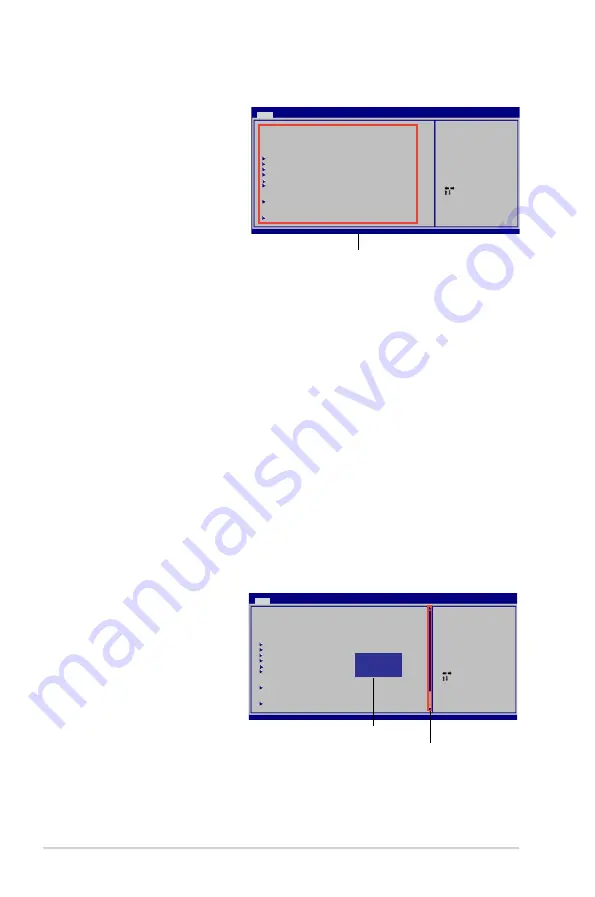
The highlighted item on the 

menu bar displays the specific 

items for that menu. For 

example, selecting Main shows 

the Main menu items.
The other items (Ai Tweaker, 

Advanced, Power, Boot, and 

Exit) on the menu bar have their 

respective menu items.

4.2.5 

Sub-menu items

A solid triangle before each item on any menu screen means that the iteam has a 

sub-menu. To display the sub-menu, select the item and press 

<Enter>

.

4.2.6 

Configuration fields

These fields show the values for the menu items. If an item is user- configurable, 

you can change the value of the field opposite the item. You cannot select an item 

that is not user-configurable.
A configurable field is enclosed in brackets, and is highlighted when selected. To 

change the value of a field, select it then press 

<Enter>

 to display a list of options. 

Refer to “

4.2.7 Pop-up window

.”

4.2.7 

Pop-up window

Select a menu item then press 

<Enter>

 to display a pop-up window with the 

configuration options for that item.

4.2.8 

Scroll bar

A scroll bar appears on the right 

side of a menu screen when 

there are items that do not fit on 

the screen. Press the  

<Up> / <Down>

 arrow keys 

or 

<Page Up> /<Page Down>


keys to display the other items 

on the screen.

4.2.9 

General help

At the top right corner of the menu screen is a brief description of the selected 

item.

Main menu items


Select Screen

    Select Item

+-   Change Field

Tab   Select Field

F1   General Help

F10   Save and Exit

ESC   Exit

v02.61 (C)Copyright 1985-2008, American Megatrends, Inc.

BIOS SETUP UTILITY

Main

    Ai Tweaker    Advanced    Power    Boot    Tools    Exit

System Time 


[14:14:35]

System Date 


[Wed 04/16/2008]

Legacy Diskette A 


[1.44M, 3.5 in]


 SATA 1 


[Not Detected]

 SATA 2 


[Not Detected]

 SATA 3 


[Not Detected]

 SATA 4 


[Not Detected]

  SATA 5 


[Not Detected]

 SATA 6 


[Not Detected]

 Storage Configuration

 System Information

Use [ENTER], [TAB] or 

[SHIFT-TAB] to select 

a field.

Use [+] or [-] to 

configure system 

Time.


Select Screen

    Select Item

+-   Change Field

Tab   Select Field

F1   General Help

F10   Save and Exit

ESC   Exit

v02.61 (C)Copyright 1985-2008, A m e r i c a n Megatrends, Inc.

BIOS SETUP UTILITY

Main

    Ai Tweaker    Advanced    Power    Boot    Tools    Exit

System Time 


[14:14:35]

System Date 


[Wed 04/16/2008]

Legacy Diskette A 


[1.44M, 3.5 in]


 SATA 1 


[Not Detected]

 SATA 2 


[Not Detected]

 SATA 3 


[Not Detected]

 SATA 4 


[Not Detected]

  SATA 5 


[Not Detected]

 SATA 6 


[Not Detected]

 Storage Configuration

 System Information

Use [ENTER], [TAB] or 

[SHIFT-TAB] to select 

a field.

Use [+] or [-] to 

configure system 

Time.

  Options

Disabled

720K,     3.5 in.

1.44M,    3.5 in.

Pop-up window

Scroll bar

Summary of Contents for P5QLD PRO

Page 1: ...Motherboard P5QLD PRO ...

Page 2: ...RCHANTABILITY OR FITNESS FOR A PARTICULAR PURPOSE IN NO EVENT SHALL ASUS ITS DIRECTORS OFFICERS EMPLOYEES OR AGENTS BE LIABLE FOR ANY INDIRECT SPECIAL INCIDENTAL OR CONSEQUENTIAL DAMAGES INCLUDING DAMAGES FOR LOSS OF PROFITS LOSS OF BUSINESS LOSS OF USE OR DATA INTERRUPTION OF BUSINESS AND THE LIKE EVEN IF ASUS HAS BEEN ADVISED OF THE POSSIBILITY OF SUCH DAMAGES ARISING FROM ANY DEFECT OR ERROR IN...

Page 3: ...2 2 2 2 1 Placement direction 2 2 2 2 2 Screw holes 2 2 2 2 3 Motherboard layout 2 3 2 2 4 Layout contents 2 4 2 3 Central Processing Unit CPU 2 6 2 3 1 Installing the CPU 2 7 2 3 2 Installing the CPU heatsink and fan 2 10 2 3 3 Uninstalling the CPU heatsink and fan 2 11 2 4 System memory 2 12 2 4 1 Overview 2 12 2 4 2 Memory configurations 2 12 2 4 3 Installing a DIMM 2 17 2 4 4 Removing a DIMM 2...

Page 4: ... 2 Creating a bootable floppy disk 4 4 4 1 3 ASUS EZ Flash 2 utility 4 5 4 1 4 AFUDOS utility 4 6 4 1 5 ASUS CrashFree BIOS 3 utility 4 8 4 2 BIOS setup program 4 10 4 2 1 BIOS menu screen 4 11 4 2 2 Menu bar 4 11 4 2 3 Navigation keys 4 11 4 2 4 Menu items 4 12 4 2 5 Sub menu items 4 12 4 2 6 Configuration fields 4 12 4 2 7 Pop up window 4 12 4 2 8 Scroll bar 4 12 4 2 9 General help 4 12 4 3 Main...

Page 5: ... 32 4 7 2 Boot Settings Configuration 4 33 4 7 3 Security 4 34 4 8 Tools menu 4 36 4 8 1 ASUS EZ Flash 2 4 37 4 8 2 Express Gate 4 37 4 8 3 AI NET 2 4 38 4 8 4 ASUS O C Profile 4 38 4 9 Exit menu 4 40 Chapter 5 Software support 5 1 Installing an operating system 5 1 5 2 Support DVD information 5 1 5 2 1 Running the support DVD 5 1 5 2 2 Drivers menu 5 2 5 2 3 Utilities menu 5 3 5 2 4 Manual menu 5...

Page 6: ...3 8 ASUS EPU 4 Engine 5 26 5 3 9 ASUS Express Gate 5 30 Appendix CPU features A 1 Intel EM64T A 1 Using the Intel EM64T feature A 1 A 2 Enhanced Intel SpeedStep Technology EIST A 1 A 2 1 System requirements A 1 A 2 2 Using the EIST A 2 A 3 Intel Hyper Threading Technology A 3 Using the Hyper Threading Technology A 3 ...

Page 7: ...n between the equipment and receiver Connect the equipment to an outlet on a circuit different from that to which the receiver is connected Consult the dealer or an experienced radio TV technician for help Canadian Department of Communications Statement This digital apparatus does not exceed the Class B limits for radio noise emissions from digital apparatus set out in the Radio Interference Regul...

Page 8: ...optional component may or may not be included in your motherboard and is defined as a CLASS 1 LASER PRODUCT DO NOT throw the mercury containing button cell battery in municipal waste This symbol of the crossed out wheeled bin indicates that the battery should not be placed in municipal waste INVISIBLE LASER RADIATION AVOID EXPOSURE TO BEAM Never dispose of the battery in fire it could explode and ...

Page 9: ...uence and ways of shutting down the system Chapter 4 BIOS setup This chapter tells how to change system settings through the BIOS Setup menus Detailed descriptions of the BIOS parameters are also provided Chapter 5 Software support This chapter describes the contents of the support CD that comes with the motherboard package Appendix CPU features The Appendix describes the CPU features and technolo...

Page 10: ...ample Enter means that you must press the Enter or Return key Key1 Key2 Key3 If you must press two or more keys simultaneously the key names are linked with a plus sign Example Ctrl Alt D Command Means that you must type the command exactly as shown then supply the required item or value enclosed in brackets Example At the DOS prompt type the command line afudos i filename afudos iP5QLDPRO ROM Whe...

Page 11: ...n system may only recognize less than 3GB Hence a total installed memory of less than 3GB is recommended if you are using a Windows 32 bit operation system Expansion Slots 1 x PCI Express x16 slot 2 x PCI Express x1 slots 3 x PCI slots Storage Intel ICH10 southbridge supports 6 x Serial ATA 3 0Gb s ports JMB368 PATA controller supports 1 x UltraDMA 133 100 66 for up to 2 PATA devices LAN PCIe Giga...

Page 12: ...2 0 1 1 ports 8 channel audio I O ports Internal Connectors 3 x USB connectors support 6 additional USB ports 1 x Floppy disk drive connector 1 x IDE connector 6 x Serial ATA connectors 1 x CPU 1 x Chassis 1 x Power fan connectors 1 x COM connector 1 x S PDIF Out header 1 x Chassis intrusion connector Front panel audio connector 1 x CD audio in connector 1 x 24 pin ATX power connector 1 x 4 pin AT...

Page 13: ...1 Product introduction This chapter describes the motherboard features and the new technologies it supports ...

Page 14: ...ASUS P5QLD PRO Chapter summary 1 1 1 Welcome 1 1 1 2 Package contents 1 1 1 3 Special features 1 2 ...

Page 15: ... motherboard and hardware devices on it check the items in your package with the list below If any of the above items is damaged or missing contact your retailer 1 2 Package contents Check your motherboard package for the following items Motherboard ASUS P5QLD PRO motherboard Cables 2 x Serial ATA signal cables 1 x Ultra DMA 133 100 66 cable Accessories 1 x I O shield 2 in 1 Q Connector Applicatio...

Page 16: ... powerful and energy efficient CPU in the world See page 2 6 for details Intel P43 Chipset The Intel P43 Express Chipset is designed to support dual channel DDR2 1066 800 667MHz architecture 1333 1066 800 FSB Front Side Bus PCIe 2 0 and multi core CPUs It supports Intel Fast Memory Access technology that significantly optimizes the use of available memory bandwidth and reduces the latency of the m...

Page 17: ...picture manager lets you view your pictures without entering Windows at anytime ASUS Power Saving Solution ASUS Power Saving solution intelligently and automatically provides balanced computing power and energy consumption ASUS EPU 4 Engine The new ASUS EPU the world s first power saving engine has been upgraded to a new four engine version which provides total system power savings by detecting cu...

Page 18: ...nt geographic regions and system loading Built in variety of useful profiles offer flexible controls of fan speed to achieve a quiet and cool environment ASUS Crystal Sound This feature can enhance speech centric applications like Skype online game video conference and recording Noise Filter This feature detects repetitive and stationary noises non voice signals like computer fans air conditioners...

Page 19: ...ils ASUS CrashFree BIOS 3 The ASUS CrashFree BIOS 3 allows users to restore corrupted BIOS data from a bootable floppy disk a USB flash disk or the motherboard support DVD containing the BIOS file See page 4 8 for details ASUS EZ Flash 2 EZ Flash 2 is a user friendly BIOS update utility Simply press the predefined hotkey to launch the utility and update the BIOS without entering the OS Update your...

Page 20: ... This feature allows you to fine tune the CPU memory voltage and gradually increase the memory Front Side Bus FSB and PCI Express frequency at 1MHz increment to achieve maximum system performance See page 4 17 to 4 22 for details C P R CPU Parameter Recall The C P R feature of the motherboard BIOS allows automatic re setting to the BIOS default settings in case the system hangs due to overclocking...

Page 21: ... Hardware information This chapter lists the hardware setup procedures that you have to perform when installing system components It includes description of the jumpers and connectors on the motherboard ...

Page 22: ... P5QLD PRO Chapter summary 2 2 1 Before you proceed 2 1 2 2 Motherboard overview 2 2 2 3 Central Processing Unit CPU 2 6 2 4 System memory 2 12 2 5 Expansion slots 2 18 2 6 Jumpers 2 21 2 7 Connectors 2 23 ...

Page 23: ...t on a grounded antistatic pad or in the bag that came with the component Before you install or remove any component ensure that the ATX power supply is switched off or the power cord is detached from the power supply Failure to do so may cause severe damage to the motherboard peripherals and or components Onboard LED The motherboard comes with a standby power LED that lights up to indicate that t...

Page 24: ...hysical injury and damage motherboard components Do not overtighten the screws Doing so can damage the motherboard 2 2 1 Placement direction When installing the motherboard make sure that you place it into the chassis in the correct orientation The edge with external ports goes to the rear part of the chassis as indicated in the image below Place this side towards the rear of the chassis 2 2 2 Scr...

Page 25: ...in module DDR2 DIMMB2 64 bit 240 pin module DDR2 DIMMA1 64 bit 240 pin module DDR2 DIMMA2 64 bit 240 pin module CD 19 3cm 7 6in CPU_FAN Intel P43 Intel ICH10 CHASSIS CLRTC FLOPPY PCIEX16 PCI1 PCI2 PCI3 PCIEX1_1 PCIEX1_2 CR2032 3V Lithium Cell CMOS Power 4Mb BIOS USBPW7 10 USBPW1112 Super I O SPDIF_OUT AAFP ALC 1200 COM1 PS2_USBPW56 ATX12V EATXPWR PANEL SB_PWR ICS 9LPRS916JGLF CHA_FAN PWR_FAN SPDIF...

Page 26: ... up 3 pin USBPW1 4 USBPW7 10 USBPW1112 2 22 Rear panel connectors Page 1 PS 2 mouse port green 2 23 2 LAN RJ 45 port 2 23 3 Rear Speaker Out port black 2 23 4 Center Subwoofer port orange 2 23 5 Line In port light blue 2 23 6 Line Out port lime 2 23 7 Microphone port pink 2 24 8 Side Speaker Out port gray 2 24 9 USB 2 0 ports 1 and 2 2 24 10 USB 2 0 ports 3 and 4 2 24 11 Coaxial S PDIF Out port 2 ...

Page 27: ...is and power fan connectors 4 pin CPU_FAN 3 pin CHA_FAN 3 pin PWR_FAN 2 29 8 Serial port connector 10 1 pin COM1 2 29 9 Chassis intrusion connector 4 1 pin CHASSIS 2 30 10 Front panel audio connector 10 1 pin AAFP 2 30 11 ATX power connectors 24 pin EATXPWR 4 pin EATX12V 2 31 12 System panel connector 20 8 pin PANEL System power LED 2 pin PLED Hard disk drive activity LED 2 pin IDE_LED System warn...

Page 28: ...ge to the PnP cap socket contacts motherboard components ASUS will shoulder the cost of repair only if the damage is shipment transit related Keep the cap after installing the motherboard ASUS will process Return Merchandise Authorization RMA requests only if the motherboard comes with the cap on the LGA775 socket The product warranty does not cover damage to the socket contacts resulting from inc...

Page 29: ...nt damage to the socket pins do not remove the PnP cap unless you are installing a CPU 2 Press the load lever with your thumb A then move it to the left B until it is released from the retention tab A B Load lever Retention tab 4 Lift the load plate with your thumb and forefinger to a 100º angle 4A then push the PnP cap from the load plate window to remove 4B 3 Lift the load lever in the direction...

Page 30: ...ermal Interface Material to the exposed area of the CPU that the heatsink will be in contact with ensuring that it is spread in an even thin layer DO NOT eat the Thermal Interface Material If it gets into your eyes or touches your skin ensure that you wash it off immediately and seek professional medical help Some heatsinks come with pre applied thermal paste If so skip this step To prevent contam...

Page 31: ... load lever B until it snaps into the retention tab A B The motherboard supports Intel LGA775 processors with the Intel Enhanced Intel SpeedStep Technology EIST and Hyper Threading Technology Refer to the Appendix for more information on these CPU features ...

Page 32: ...A775 processor requires a specially designed heatsink and fan assembly to ensure optimum thermal condition and performance When you buy a boxed Intel processor the package includes the CPU fan and heatsink assembly If you buy a CPU separately ensure that you use only Intel certified multi directional heatsink and fan Your Intel LGA775 heatsink and fan assembly comes in a push pin design and requir...

Page 33: ...diagonal sequence to disengage the heatsink and fan assembly from the motherboard A A B B A A B B 4 Carefully remove the heatsink and fan assembly from the motherboard 3 Connect the CPU fan cable to the connector on the motherboard labeled CPU_FAN Do not forget to connect the CPU fan connector Hardware monitoring errors can occur if you fail to plug this connector P5QLD PRO CPU Fan Connector GND C...

Page 34: ...ates the location of the DDR2 DIMM sockets P5QLD PRO 240 pin DDR2 DIMM Sockets 128 Pins 112 Pins DIMM_A2 DIMM_B1 DIMM_B2 DIMM_A1 P5QLD PRO 2 4 2 Memory configurations You may install 512MB 1GB 2GB and 4GB unbuffered non ECC DDR2 DIMMs into the DIMM sockets Recommended Memory Configurations Mode Sockets DIMM_A1 DIMM_A2 DIMM_B1 DIMM_B2 Single Channel Populated Populated Dual channel 1 Populated Popu...

Page 35: ...hen you want to install 4GB or more memory on the motherboard This motherboard does not support DIMMs made up of 256 megabits Mb chips or less The default memory operation frequency is dependent on its SPD Under the default state some memory modules for overclocking may operate at a lower frequency than the vendor marked value To operate at the vendor marked or at a higher frequency see section 4 ...

Page 36: ...ize Vendor Part No CL Chip Brand SS DS Chip No DIMM support A B C 1G Kingston KHX6400D2LL 1G N A Kingston DS Heat Sink Package 512MB Kingston KHX6400D2LLK2 1GN N A Kingston SS Heat Sink Package 512MB Kingston KVR800D2N5 512 N A Promos SS V59C1512804QCF25SY032406PECPA 512MB Kingston KVR800D2N6 512 N A Elpida SS E5108AJBG 8E E 1G Kingston KVR800D2N5 1G N A Elpida DS E5108AJBG 8E E 1G Kingston KVR800...

Page 37: ...6400C4DC 4 GEIL DS GL2L128M88BA25AB 2G GEIL GB24GB6400C5DC 5 GEIL DS GL2L128M88BA25AB 2G GEIL GB28GB6400C5QC 5 GEIL DS GL2L128M88BA25AB 2G GEIL GB28GB6400C4QC 4 GEIL DS GL2L128M88BA25AB 2G GEIL GX22GB6400LX 5 GEIL DS Heat Sink Package 2G GEIL GX24GB6400DC 5 GEIL DS Heat Sink Package 2G GEIL GE28GB800C5QC 5 GEIL DS Heat Sink Package 2G GEIL GE28GB800C4QC 4 GEIL DS Heat Sink Package 2G GEIL GX22GB64...

Page 38: ...B5 N A Kingmax DS KKEA88B4LAUG 29DX 512MB Apacer AU512E667C5KBGC 5 Apacer SS AM4B5708MIJS7E0627B 512MB Apacer AU512E667C5KBGC 5 Apacer SS AM4B5708GQJS7E06332F 512MB Apacer 78 91G92 9K5 5 Apacer SS AM4B5708JQJS7E0751C 1G Apacer 78 01G9O 9K5 5 Apacer SS AM4B5808CQJS7E0751C 1G Apacer AU01GE667C5KBGC N A Apacer DS AM4B5708GQJS7E0636B 1G Apacer AU01GE667C5KBGC 5 Apacer DS AM4B5708MIJS7E0627B 2G Apacer ...

Page 39: ...when pressing the retaining clips The DIMM might get damaged when it flips out with extra force 3 Firmly insert the DIMM into the socket until the retaining clips snap back in place and the DIMM is properly seated A DDR2 DIMM is keyed with a notch so that it fits in only one direction DO NOT force a DIMM into a socket to avoid damaging the DIMM Unlocked retaining clip 1 DDR2 DIMM notch 1 Unlock a ...

Page 40: ... Secure the card to the chassis with the screw you removed earlier 6 Replace the system cover Ensure to unplug the power cord before adding or removing expansion cards Failure to do so may cause you physical injury and damage motherboard components When using PCI cards on shared slots ensure that the drivers support Share IRQ or that the cards do not need IRQ assignments Otherwise conflicts will a...

Page 41: ...d shared shared shared PCIE X16 slot shared shared shared shared Onboard USB1 1 controller 1 shared Onboard USB1 1 controller 2 shared Onboard USB1 1 controller 3 shared Onboard USB1 1 controller 4 shared Onboard USB1 1 controller 5 shared Onboard USB1 1 controller 6 shared Onboard USB1 1 controller 7 shared Onboard USB2 0 controller 1 shared Onboard USB2 0 controller 2 shared Onboard IDE PORT sha...

Page 42: ... Express x1 slots This motherboard supports PCI Express x1 network cards SCSI cards and other cards that comply with the PCI Express specifications The following photo shows a network card installed on the PCI Express x1 slot 2 5 6 PCI Express x16 slot This motherboard supports one PCI Express x16 graphics card that complies with the PCI Express specifications The photo shows a graphics card insta...

Page 43: ...stall the battery 5 Plug the power cord and turn ON the computer 6 Hold down the Del key during the boot process and enter BIOS setup to re enter data You do not need to clear the RTC when the system hangs due to overclocking For system failure due to overclocking use the C P R CPU Parameter Recall feature Shut down and reboot the system so the BIOS can automatically reset parameter settings to de...

Page 44: ...ing in the BIOS The jumper is for the rear USB ports P5QLD PRO USB Device Wake Up 3 2 2 1 USBPW1112 Default 5V 5VSB 3 2 2 1 USBPW7 10 Default 5V 5VSB P5QLD PRO 3 2 2 1 USBPW1 4 Default 5V 5VSB 3 USB device wake up 3 pin USBPW1 4 USBPW7 10 USBPW1112 Set these jumpers to 5V to wake up the computer from S1 sleep mode CPU stopped DRAM refreshed system running in low power mode using the connected USB ...

Page 45: ...t light blue This port connects the tape CD DVD player or other audio sources 6 Line Out port lime This port connects a headphone or a speaker In 4 channel 6 channel and 8 channel configuration the function of this port becomes Front Speaker Out LAN port LED indications ACT LINK LED SPEED LED Status Description Status Description OFF No link OFF 10 Mbps connection YELLOW Linked ORANGE 100 Mbps con...

Page 46: ...8 channel configuration 7 Microphone port pink This port connects a microphone 8 Side Speaker Out port gray This port connects the side speakers in an 8 channel audio configuration 9 USB 2 0 ports 1 and 2 These two 4 pin Universal Serial Bus USB ports are available for connecting USB 2 0 devices 10 USB 2 0 ports 3 and 4 These two 4 pin Universal Serial Bus USB ports are available for connecting US...

Page 47: ...cable connection when using a FDD cable with a covered Pin 5 P5QLD PRO Floppy Disk Drive Connector PIN1 NOTE Orient the red markings on the floppy ribbon cable to PIN 1 FLOPPY P5QLD PRO 2 Digital audio connector 4 1 pin SPDIF_OUT This connector is for an additional Sony Philips Digital Interface S PDIF port s Connect the S PDIF Out module cable to this connector then install the module to a slot o...

Page 48: ...in 20 on the IDE connector is removed to match the covered hole on the Ultra DMA cable connector This prevents incorrect insertion when you connect the IDE cable Use the 80 conductor IDE cable for Ultra DMA 133 100 66 IDE devices If any device jumper is set as Cable Select make sure all other device jumpers have the same setting Drive jumper setting Mode of device s Cable connector Single device C...

Page 49: ... port to avoid mechanical conflict with huge graphics cards right angle side P5QLD PRO SATA Connectors GND RSATA_TXP6 RSATA_TXN6 GND RSATA_RXN6 RSATA_RXP6 GND SATA6 GND RSATA_TXP5 RSATA_TXN5 GND RSATA_RXN5 RSATA_RXP5 GND SATA5 GND RSATA_TXP3 RSATA_TXN3 GND RSATA_RXN3 RSATA_RXP3 GND SATA3 GND RSATA_TXP1 RSATA_TXN1 GND RSATA_RXN1 RSATA_RXP1 GND SATA1 GND RSATA_TXP4 RSATA_TXN4 GND RSATA_RXN4 RSATA_RX...

Page 50: ...the ASUS Q Connector USB blue first and then install the Q Connector USB to the USB connector onboard if your chassis supports front panel USB ports The USB module cable is purchased separately P5QLD PRO USB 2 0 Connectors USB78 USB 5V USB_P8 USB_P8 GND NC USB 5V USB_P7 USB_P7 GND 1 USB1112 USB 5V USB_P12 USB_P12 GND NC USB 5V USB_P11 USB_P11 GND 1 USB910 USB 5V USB_P10 USB_P10 GND NC USB 5V USB_P...

Page 51: ...ir flow inside the system may damage the motherboard components These are not jumpers Do not place jumper caps on the fan connectors Only the 4 pin CPU_FAN connector supports the ASUS Q FAN feature 8 Serial port connector 10 1 pin COM1 This connector is for a serial COM port Connect the serial port module cable to this connector then install the module to a slot opening at the back of the system c...

Page 52: ...Audio or legacy AC 97 audio standard Connect one end of the front panel audio I O module cable to this connector We recommend that you connect a high definition front panel audio module to this connector to avail of the motherboard s high definition audio capability If you want to connect a high definition front panel audio module to this connector set the Front Panel Type item in the BIOS setup t...

Page 53: ... power requirements with the following configuration CPU Intel Pentium Extreme 3 73GHz Memory 512 MB DDR2 x4 Graphics card ASUS EAX1900XT Parallel ATA device IDE hard disk drive Serial ATA device SATA hard disk drive x2 Optical drive DVD RW 11 ATX power connectors 24 pin EATXPWR 4 pin EATX12V These connectors are for ATX power supply plugs The power supply plugs are designed to fit these connector...

Page 54: ...speaker The speaker allows you to hear system beeps and warnings ATX power button soft off button 2 pin PWRSW This connector is for the system power button Pressing the power button turns the system on or puts the system in sleep or soft off mode depending on the BIOS settings Pressing the power switch for more than four seconds while the system is ON turns the system OFF Reset button 2 pin RESET ...

Page 55: ...nly a few steps Directions below shows how to install ASUS Q Connector Step2 Properly install the ASUS Q Connector to the System panel connctor Step1 Connect correct front panel to ASUS Q Connector first You can refer to the marking on Q Connector itself to know the detail pin definition Step3 Front panel functions are enabled ...

Page 56: ...2 34 Chapter 2 Hardware information ...

Page 57: ...3 Powering up This chapter describes the power up sequence the vocal POST messages and ways of shutting down the system ...

Page 58: ...ASUS P5QLD PRO Chapter summary 3 3 1 Starting up for the first time 3 1 3 2 Turning off the computer 3 2 ...

Page 59: ...e monitor LED may light up or switch between orange and green after the system LED turns on The system then runs the power on self tests or POST While the tests are running the BIOS beeps see BIOS beep codes table below or additional messages appear on the screen If you do not see anything within 30 seconds from the time you turned on the power the system may have failed a power on self test Check...

Page 60: ...are using Windows Vista 1 Click the Start button then select ShutDown 2 The power supply should turn off after Windows shuts down 3 2 2 Using the dual function power switch While the system is ON pressing the power switch for less than four seconds puts the system to sleep mode or to soft off mode depending on the BIOS setting Pressing the power switch for more than four seconds lets the system en...

Page 61: ...4 BIOS setup This chapter tells how to change the system settings through the BIOS Setup menus Detailed descriptions of the BIOS parameters are also provided ...

Page 62: ... P5QLD PRO 4 1 Managing and updating your BIOS 4 1 4 2 BIOS setup program 4 10 4 3 Main menu 4 13 4 4 Ai Tweaker menu 4 17 4 5 Advanced menu 4 22 4 6 Power menu 4 28 4 7 Boot menu 4 31 4 8 Tools menu 4 36 4 9 Exit menu 4 40 ...

Page 63: ...DOS utilities Installing ASUS Update To install ASUS Update 1 Place the support DVD in the optical drive The Drivers menu appears 2 Click the Utilities tab then click Install ASUS Update 3 The ASUS Update utility is copied to your system 4 1 1 ASUS Update utility The ASUS Update is a utility that allows you to manage save and update the motherboard BIOS in Windows environment The ASUS Update utili...

Page 64: ...ext Updating the BIOS through the Internet To update the BIOS through the Internet 1 Launch the ASUS Update utility from the Windows desktop by clicking Start Programs ASUS ASUSUpdate ASUSUpdate The ASUS Update main window appears 2 Select Update BIOS from the Internet option from the drop down menu then click Next ...

Page 65: ... file option from the drop down menu then click Next 4 From the FTP site select the BIOS version that you wish to download Click Next 5 Follow the screen instructions to complete the update process The ASUS Update utility is capable of updating itself through the Internet Always update the utility to avail all its features 3 Locate the BIOS file from the Open window then click Open 4 Follow the sc...

Page 66: ...2 Floppy Drive icon d Click File from the menu then select Format A Format 3 1 2 Floppy Disk window appears e Select Create an MS DOS startup disk from the format options field then click Start Windows Vista environment a Insert a formatted high density 1 44 MB floppy disk to the floppy disk drive b Click from the Windows desktop then select Computer c Right click Floppy Disk Drive then click Form...

Page 67: ...ive or the USB port Press Alt F2 during POST to display the following This function can support devices such as USB flash disk or floppy disk with FAT 32 16 format and single partition only Do not shut down or reset the system while updating the BIOS to prevent system boot failure ASUSTek EZ Flash 2 BIOS ROM Utility V3 24 Current ROM Update ROM A Note FLASH TYPE MXIC 25L8005 PATH A BOARD P5QLD Pro...

Page 68: ...for the main filename and three alphanumeric characters for the extension name Main filename Extension name A afudos oOLDBIOS1 rom Make sure that the floppy disk is not write protected and has at least 1024KB free space to save the file The succeeding BIOS screens are for reference only The actual BIOS screen displays may not be the same as shown The utility returns to the DOS prompt after copying...

Page 69: ...ROM AMI Firmware Update Utility Version 1 19 ASUS V2 07 03 11 24BB Copyright C 2002 American Megatrends Inc All rights reserved WARNING Do not turn off power during flash BIOS Reading file done Reading flash done Advance Check Erasing flash done Writing flash done Verifying flash done Please restart your computer A A afudos iP5QLDPRO ROM AMI Firmware Update Utility Version 1 19 ASUS V2 07 03 11 24...

Page 70: ...the SATA1 SATA 2 connector otherwise the utility will not function Recovering the BIOS from a floppy disk To recover the BIOS from a floppy disk 1 Turn on the system 2 Insert the floppy disk with the original or updated BIOS file to the floppy disk drive 3 The utility displays the following message and automatically checks the floppy disk for the original or updated BIOS file Bad BIOS checksum Sta...

Page 71: ... flash disk 1 Insert a USB flash disk that contains BIOS file to the USB port 2 Turn on the system 3 The utility will automatically checks the devices for the BIOS file When found the utility reads the BIOS file and starts flashing the corrupted BIOS file 4 Restart the system after the utility completes the updating process Bad BIOS checksum Starting BIOS recovery Checking for floppy Bad BIOS chec...

Page 72: ... If you wish to enter Setup after POST reboot the system by doing any of the following procedures Restart using the OS standard shut down procedure Press Ctrl Alt Del simultaneously Press the reset button on the system chassis Press the power button to turn the system off then back on The default BIOS settings for this motherboard apply for most conditions to ensure optimum performance If the syst...

Page 73: ...on keys differ from one screen to another Select Screen Select Item Change Field Tab Select Field F1 General Help F10 Save and Exit ESC Exit v02 61 C Copyright 1985 2008 American Megatrends Inc BIOS SETUP UTILITY Main Ai Tweaker Advanced Power Boot Tools Exit System Time 14 14 35 System Date Wed 04 16 2008 Legacy Diskette A 1 44M 3 5 in SATA 1 Not Detected SATA 2 Not Detected SATA 3 Not Detected S...

Page 74: ...keys or Page Up Page Down keys to display the other items on the screen 4 2 9 General help At the top right corner of the menu screen is a brief description of the selected item Main menu items Select Screen Select Item Change Field Tab Select Field F1 General Help F10 Save and Exit ESC Exit v02 61 C Copyright 1985 2008 American Megatrends Inc BIOS SETUP UTILITY Main Ai Tweaker Advanced Power Boot...

Page 75: ...n 4 2 1 BIOS menu screen for information on the menu screen items and how to navigate through them Select Screen Select Item Change Field Tab Select Field F1 General Help F10 Save and Exit ESC Exit v02 61 C Copyright 1985 2008 American Megatrends Inc BIOS SETUP UTILITY Main Ai Tweaker Advanced Power Boot Tools Exit System Time 14 14 35 System Date Wed 04 16 2008 Legacy Diskette A 1 44M 3 5 in SATA...

Page 76: ...he LBA mode if the device supports this mode and if the device was not previously formatted with LBA mode disabled Configuration options Disabled Auto Block Multi sector Transfer M Auto Enables or disables data multi sectors transfers When set to Auto the data transfer from and to the device occurs multiple sectors at a time if the device supports multi sector transfer feature When set to Disabled...

Page 77: ...to set or change the configurations for the SATA devices installed in the system Select an item then press Enter if you want to configure the item SATA Configuration SATA Configuration Enhanced Configure SATA as IDE Hard Disk Write Protect Disabled IDE Detect Time Out Sec 35 Options Disabled Compatiable Enhanced Hard Disk Write Protect Disabled Disables or enables device write protection This will...

Page 78: ...rocessor Displays the auto detected CPU specification System Memory Displays the auto detected system memory Select Screen Select Item F1 General Help F10 Save and Exit ESC Exit v02 61 C Copyright 1985 2008 American Megatrends Inc BIOS SETUP UTILITY Main Bios Information Version 0314 Build Date 05 27 08 Processor Type Intel R Core TM 2 CPU 6300 1 86GHz Speed 1866MHz Count 2 System Memory Installed...

Page 79: ... Transaction Booster Auto C P A1 A2 A3 A4 LVL 09 09 09 09 Please Key in numbers directly CPU Voltage Auto FSB Termination Voltage Auto Manual Auto Take caution when changing the settings of the Extreme Tweaker menu items Incorrect field values can cause the system to malfunction Scroll down to display the following items v02 61 C Copyright 1985 2008 American Megatrends Inc Memory Voltage Auto Nort...

Page 80: ... frequency using the numeric keypad The values range from 100 to 180 FSB Strap to North Bridge Auto Allows you to adjust the FSB strap Configuration options Auto 200MHz 266MHz 333MHz 400MHz DRAM Frequency Auto Allows you to set the DDR2 operating frequency Configuration options Auto DDR2 533MHz DDR2 639MHz DDR2 667MHz DDR2 709MHz DDR2 800MHz DDR2 852MHz DDR2 887MHZ DDR2 1066MHz DRAM Timing Control...

Page 81: ...options Auto 1 DRAM Clocks 15 DRAM Clocks Read to Precharge Time Auto Configuration options Auto 1 DRAM Clocks 15 DRAM Clocks 2nd Information 8 3 5 4 6 4 6 READ to WRITE Delay S D Auto Configuration options Auto 1 DRAM Clocks 15 DRAM Clocks WRITE to READ Delay S Auto Configuration options Auto 1 DRAM Clocks 15 DRAM Clocks WRITE to READ Delay D Auto Configuration options Auto 1 DRAM Clocks 15 DRAM ...

Page 82: ...ns Auto Disabled Enabled MEM OC Charger Auto Adjusting this item might enhance DRAM overclocking ability Configuration options Auto Disabled Enabled Ai Clock Twister Auto Allows you to set the DRAM performance Set this item to Light or Lighter to enhance DRAM compatibility or Strong or Stronger to accelerate DRAM performance Configuration options Auto Lighter Light Moderate Strong Stronger Ai Tran...

Page 83: ... standard values become 1 10V when 45nm CPU is detected Memory Voltage Auto Allows you to set the memory voltage manually or Auto Use the and keys to adjust the value Configuration options Auto North Bridge Voltage Auto Allows you to set the NB voltage manually or Auto Use the and keys to adjust the value Configuration options Auto Setting a very high voltage may damage the component permanently a...

Page 84: ...ange the settings for the CPU and other system devices Take caution when changing the settings of the Advanced menu items Incorrect field values can cause the system to malfunction v02 61 C Copyright 1985 2008 American Megatrends Inc BIOS SETUP UTILITY Main Ai Tweaker Advanced Power Boot Tools Exit CPU Configuration Chipset Onboard Devices Configuration USB Configuration PCIPnP Select Screen Selec...

Page 85: ...U core clock and the FSB frequency Configuration options Auto Sets the ratio between CPU Core Clock and the FSB Frequency NOTE If an invalid ratio is set in CMOS then actual and setpoint values may differ C1E Support Enabled Allows you to enable or disable C1E Support Configuration options Disabled Enabled Max CPUID Value Limit Disabled Setting this item to Enabled allows legacy operating systems ...

Page 86: ...ture Set this item to Disabled if you do not want to use the EIST Configuration options Enabled Disabled The following item appears only when you installed an Intel Pentium 4 or later CPU that supports the Enhanced Intel SpeedStep Technology EIST 4 5 2 Chipset The Chipset menu allows you to change the advanced chipset settings Select an item then press Enter to display the sub menu Advanced Chipse...

Page 87: ...dio Enabled Front Panel Type HD Audio SPDIF_OUT Mode Setting SPDIF Output JMB368 IDE controller Enabled Onboard PCIE GbE LAN Enabled LAN Option ROM Disabled Serial Port1 Address 3F8 IRQ4 Enable or Disable High Definition Audio Controller BIOS SETUP UTILITY Advanced High Definition Audio Enabled Allows you to enable or disable the High Definition Audio The following item appears only when you enabl...

Page 88: ...ion options The USB Devices Enabled item shows auto detected values If no USB device is detected the item shows None USB Functions Enabled Allows you to enable or disable the USB functions Configuration options Disabled Enabled USB 2 0 Controller Enabled Allows you to enable or disable the USB 2 0 controller Configuration options Enabled Disabled Select Screen Select Item Change Option F1 General ...

Page 89: ... No When set to No BIOS configures all the devices in the system When set to Yes and if you install a Plug and Play operating system the operating system configures the Plug and Play devices not required for boot Configuration options No Yes USB 2 0 Controller Mode HiSpeed Allows you to set the USB 2 0 controller mode to HiSpeed 480 Mbps or FullSpeed 12 Mbps This item appears only when you enable ...

Page 90: ...n signaled by a wake up device or event the system resumes to its working state exactly where it was left off Auto Detected by OS Select Screen Select Item Change Option F1 General Help F10 Save and Exit ESC Exit v02 61 C Copyright 1985 2008 American Megatrends Inc Suspend Mode Auto ACPI 2 0 Support Disabled ACPI APIC Support Enabled APM Configuration Hardware Monitor Select the ACPI state used fo...

Page 91: ...ptions Disabled Enabled Select Screen Select Item Change Option F1 General Help F10 Save and Exit ESC Exit v02 61 C Copyright 1985 2008 American Megatrends Inc APM Configuration Restore on AC Power Loss Power Off Power On By RTC Alarm Disabled Power On By External Modems Disabled Power On By PCI Devices Disabled Power On By PCIE Devices Disabled Power On By PS 2 Keyboard Disabled Power On By PS 2 ...

Page 92: ...erature v02 61 C Copyright 1985 2008 American Megatrends Inc BIOS SETUP UTILITY Power Hardware Monitor CPU Temperature 25ºC 77ºF MB Temperature 41ºC 105 5ºF CPU Fan Speed 4440RPM CPU Q Fan Control Disabled Chassis Fan Speed N A Power Fan Speed N A CPU Voltage 1 080V 3 3V Voltage 3 232V 5V Voltage 5 040V 12V Voltage 12 208V Power On By PS 2 Keyboard Disabled Allows you to disable the Power On by PS...

Page 93: ...ows N A CPU Voltage 3 3V Voltage 5V Voltage 12V Voltage xxxxV or Ignored The onboard hardware monitor automatically detects the voltage output through the onboard voltage regulators Select Ignored if you do not want to detect this item 4 7 Boot menu The Boot menu items allow you to change the system boot options Select an item then press Enter to display the sub menu Select Screen Select Item Ente...

Page 94: ...guration options 1st FLOPPY DRIVE Hard Drive ATAPI CD ROM Disabled Select Screen Select Item Change Option F1 General Help F10 Save and Exit ESC Exit v02 61 C Copyright 1985 2008 American Megatrends Inc Boot Device Priority 1st Boot Device 1st FLOPPY DRIVE 2nd Boot Device Hard Drive 3rd Boot Device ATAPI CD ROM Specifies the boot sequence from the availabe devices A device enclosed in parenthesis ...

Page 95: ... AddOn ROM Display Mode Force BIOS Bootup Num Lock On PS 2 Mouse Support Auto Wait For F1 If Error Enabled Hit DEL Message Display Enabled Interrupt 19 Capture Disabled Allows BIOS to skip certain tests while booting This will decrease the time needed to boot the system BIOS SETUP UTILITY Boot Set this item to Enabled to use the ASUS MyLogo2 feature AddOn ROM Display Mode Force BIOS Sets the displ...

Page 96: ... run Setup during POST Configuration options Disabled Enabled Interrupt 19 Capture Disabled When set to Enabled this function allows the option ROMs to trap Interrupt 19 Configuration options Disabled Enabled Change Supervisor Password Select this item to set or change the supervisor password The Supervisor Password item on top of the screen shows the default Not Installed After you set a password...

Page 97: ...lect this item to set or change the user password The User Password item on top of the screen shows the default Not Installed After you set a password this item shows Installed To set a User Password 1 Select the Change User Password item and press Enter 2 On the password box key in a password containing up to six letter or numbers or both then click Enter 3 Confirm the password when prompted Sele...

Page 98: ...e Press ENTER to run the utility to select and update BIOS This utility doesn t support 1 NTFS format BIOS SETUP UTILITY Main Ai Tweaker Advanced Power Boot Tools Exit The message Password Installed appears after you set your password successfully To change the user password follow the same steps in setting a user password Clear User Password Select this item to clear the user password Password Ch...

Page 99: ... User 1 second 3 seconds 5 seconds 10 seconds 15 seconds 20 seconds 30 seconds Reset User Data No Allows you to clear Express Gate s user data Configuration options No Reset When setting this item to Reset make sure to save the setting to the BIOS so that the user data will be cleared the next time you enter the Express Gate User data includes the Express Gate s settings as well as any personal in...

Page 100: ...s LAN cable Disabled Check Atheros LAN cable during POST BIOS SETUP UTILITY Tools 4 8 4 ASUS O C Profile Select Screen Select Item Enter Go to Sub Screen F1 General Help F10 Save and Exit ESC Exit v02 61 C Copyright 1985 2008 American Megatrends Inc O C PROFILE Configuration O C Profile 1 Status Not Installed O C Profile 2 Status Not Installed Save to Profile 1 Load from Profile 1 Save to Profile ...

Page 101: ...e utility to save and load CMOS Press Enter to run the utility This function can support devices such as USB flash disk or floppy disk with FAT 32 16 format and single partition only DO NOT shut down or reset the system while updating the BIOS to prevent the system boot failure ASUSTek O C Profile Utility V1 24 Current CMOS Update CMOS A Note PATH A BOARD P5QLD Pro VER 0314 H 00 B 03 DATE 05 27 20...

Page 102: ...ion a confirmation appears Select OK to discard any changes and load the previously saved values Load Setup Defaults This option allows you to load the default values for each of the parameters on the Setup menus When you select this option or if you press F5 a confirmation window appears Select OK to load default values Select Exit Save Changes or make other changes before saving the values to th...

Page 103: ...5 Software support This chapter describes the contents of the support CD that comes with the motherboard package ...

Page 104: ...ASUS P5QLD PRO Chapter summary 5 5 1 Installing an operating system 5 1 5 2 Support DVD information 5 1 5 3 Software information 5 10 ...

Page 105: ...run is enabled in your computer Motherboard settings and hardware options vary Use the setup procedures presented in this chapter for reference only Refer to your OS documentation for detailed information Ensure that you install the Windows XP Service Pack3 or later versions before installing the drivers for better compatibility and system stability The contents of the support DVD are subject to c...

Page 106: ... ASUS InstAll Installation wizard for drivers Norton Internet Security 2009 Installs the Norton Internet security 2009 Realtek Audio Driver Installs the Realtek ALC1200 audio driver and application Intel Chipset Inf Update Program Installs the Intel chipset Inf update program Atheros AR8121 PCI E Ethernet Controller Installs the Atheros AR8121 PCI E Ethernet controller ASUS EPU 4 Engine Installs t...

Page 107: ...y detected problems This utility helps you keep your computer in healthy operating condition ASUS Update The ASUS Update utility allows you to update the motherboard BIOS in a Windows environment This utility requires an Internet connection either through a network or an Internet Service Provider ISP ASUS AI Suite The ASUS AI Suite is an innovative application to do overclocking fan control power ...

Page 108: ...aphics and sound DirectX improves the multimedia features of you computer so you can enjoy watching TV and movies capturing videos or playing games in your computer Visit the Microsoft website at http www microsoft com for updates ASUS Express Gate Installer Allows you to install or update Express Gate functions Atheros Ethernet Utility Installs the Atheros Ethernet utility ...

Page 109: ...rtable Document Format PDF Install the Adobe Reader from the Utilities menu before opening a user manual file Realtek HD Audio User s Manual Allows you to open the Realtek HD Audio User Manual NIS 2009 Subscription Renewal Guide Allows you to open the NIS 2009 Subscription Renewal Guide ASUS Motherboard Installation Guide Allows you to open the ASUS Motherboard Installation Guide ...

Page 110: ...5 Chapter 5 Software support 5 2 5 ASUS Contact information Click the Contact tab to display the ASUS contact information You can also find this information on the inside front cover of this user guide ...

Page 111: ...ormat 5 2 6 Other information The icons on the top right corner of the screen give additional information on the motherboard and the contents of the support DVD Click an icon to display the specified information Motherboard Info Displays the general specifications of the motherboard ...

Page 112: ...5 Chapter 5 Software support Filelist Displays the contents of the support DVD and a brief description of each in text format ...

Page 113: ...ty for details 2 Select Options from the drop down menu then click Next 3 Check the option Launch MyLogo to replace system boot logo before flashing BIOS then click Next 4 Select Update BIOS from a file from the drop down menu then click Next 5 When prompted locate the new BIOS file then click Next The ASUS MyLogo window appears 6 From the left window pane select the folder that contains the image...

Page 114: ...l BIOS to load the new boot logo 10 After flashing the BIOS restart the computer to display the new boot logo during POST 8 Adjust the boot image to your desired size by selecting a value on the Ratio box 7 When the logo images appear on the right window pane select an image to enlarge by clicking on it ...

Page 115: ...orts eliminating cable connection errors and giving users plug and play convenience Follow the installation wizard to install the Realtek Audio Driver from the Support DVD that came with the motherboard package If the Realtek audio software is correctly installed you will find the Realtek HD Audio Manager icon on the taskbar From the taskbar double click on the SoundEffect icon to display the Real...

Page 116: ... in this area to configure your audio settings Sound Effect The Realtek ALC1200 Audio CODEC allows you to set your listening environment adjust the equalizer set the karaoke or select pre programmed equalizer settings for your listening pleasure To set the sound effect options 1 From the Realtek HD Audio Manager click the Sound Effect tab 2 Click the shortcut buttons or the drop down menus for opt...

Page 117: ... Synth Front Rear CD volume Mic volume Line Volume and Stereo mix etc by clicking the control tabs and dragging them up and down until you get the desired levels Click the next button to display more menu options 4 Click to effect the Mixer settings and exit Audio I O TheAudio I O option allows you configure your input output settings To set the Audio I O options 1 From the Realtek HD Audio Manage...

Page 118: ...kground noise when recording 3 Click the Acoustic Echo Cancellation option button to reduce the echo from the front speakers when recording 4 Click to effect the Microphone settings and exit 3D Audio Demo The 3D Audio Demo option gives you a demonstration of the 3D audio feature To start the 3D Audio Demo 1 FromtheRealtekHDAudioManager click the 3D Audio Demo tab 2 Click the option buttons to chan...

Page 119: ...xe file from the ASUS PC Probe II folder Double click the setup exe file to start installation 2 Click the Utilities tab then click ASUS PC Probe II 3 Follow the screen instructions to complete installation Launching PC Probe II You can launch the PC Probe II right after installation or anytime from the Windows desktop To launch the PC Probe II from the Windows desktop click Start All Programs ASU...

Page 120: ...turns red Refer to the Monitor panels section for details Button Function Opens the Configuration window Opens the Report window Opens the Desktop Management Interface window Opens the Peripheral Component Interconnect window Opens the Windows Management Instrumentation window Opens the hard disk drive memory CPU usage window Shows Hides the Preference section Minimizes the application Closes the ...

Page 121: ...he hardware monitor panels display the current value of a system sensor such as fan rotation CPU temperature and voltages The hardware monitor panels come in two display modes hexagonal large and rectangular small When you check the Enable Monitoring Panel option from the Preference section the monitor panels appear on your computer s desktop Large display Small display Click to increase value Cli...

Page 122: ...ser displays various Windows management information Click an item from the left panel to display on the right panel Click the plus sign before WMI Information to display the available information You can enlarge or reduce the browser size by dragging the bottom right corner of the browser DMI browser Click to display the DMI Desktop Management Interface browser This browser displays various deskto...

Page 123: ...ory usage Click to display the Usage browser CPU usage The CPU tab displays real time CPU usage in line graph representation If the CPU has an enabled Hyper Threading two separate line graphs display the operation of the two logical processors Hard disk drive space usage The Hard Disk tab displays the used and available hard disk drive space The left panel of the tab lists all logical drives Click...

Page 124: ...the sensor threshold values The Config window has two tabs Sensor Threshold and Preference The Sensor Threshold tab enables you to activate the sensors or to adjust the sensor threshold values The Preference tab allows you to customize sensor alerts or change the temperature scale Loads the default threshold values for each sensor Applies your changes Cancels or ignores your changes Loads your sav...

Page 125: ...aunching AI Suite You can launch AI Suite right after installation or anytime from the Windows desktop To launch AI Suite from the Windows desktop click Start All Programs ASUS AI Suite AI Suite v1 xx xx The AI Suite main window appears After launching the application the AI Suite icon appears in the Windows taskbar Click this icon to close or restore the application Using AI Suite Click the AI Na...

Page 126: ...f the main window to open the monitor window Click on right corner of the expanded window to switch the temperature from degrees Centigrade to degrees Fahrenheit Displays the CPU system temperature CPU memory PCIE voltage and CPU chassis fan speed Displays the FSB CPU frequency ...

Page 127: ... After installing AI Suite from the bundled support DVD you can launch the utility by double clicking the AI Suite icon on the Windows OS taskbar and click the AI Booster button on the AI Suite main window The options on the taskbar allow you to use the default settings adjust CPU Memory PCI E frequency manually or create and apply your personal overclocking configurations ...

Page 128: ...you can launch the utility by double clicking the AI Suite icon on the Windows OS taskbar and click the AI Nap button on the AI Suite main window Click Yes on the confirmation screen To exit AI Nap mode press the system power or mouse button then click Yes on the confirmation screen To switch the power button functions from AI Nap to shutting down just right click the AI Suite icon on the OS taskb...

Page 129: ...ols of fan speed to achieve a quiet and cool environment Install AI Suite from the bundled support DVD To launch the ASUS Fan Xpert utility double click the AI Suite icon on the Windows notification bar and click the Fan Xpert button on the AI Suite main window Dropdown list button Click to display the dropdown list and select a fan profile mode Click to display the current CPU temperature and the...

Page 130: ...Fan Control Installing 4 Engine To install 4 Engine on your computer 1 Place the support DVD to the optical drive The Drivers menu appears if Autorun is enabled on your computer 2 Click ASUS EPU 4 Engine 3 Follow the screen instructions to complete installation Launching 4 Engine Launch 4 Engine by double clicking the 4 Engine icon on the Windows notification area The first time you launch 4 Engin...

Page 131: ...isplay of Total and Current CO2 reduced Displays the amount of CO2 reduced Displays the following message if no VGA power saving engine is detected Exits the utility Displays the system properties of each mode Displays current mode Lights up when power saving engine is activated Click Current to show the CO2 that has been reduced since you click the Renew button Click Total to show the total CO2 t...

Page 132: ... The following lists the configuration options and their definitions in Setting menu vCore Voltage Downgrade Lowers CPU vCore voltage High Downgrades voltage to the highest level for CPU power saving Medium Downgrades voltage to the medium level Small Downgrades voltage to the minimum level Turn Off hard disks Turns off hard disk drives when they are not accessed after a certain time CPU Loadline ...

Page 133: ...edium Heavy Light Medium Heavy Fan Control N A N A Keep Bios Setting Slow Keep Bios Setting Quiet AI Nap Idle Time Never After 3 mins After 5 hours Never After 3 mins After 5 hours Never After 3 mins After 5 hours Never After 3 mins After 5 hours Refer to the following table for the configuration options in each mode Fan Control Adjusts fan speeds to reduce noise and save system power Quiet Lowers...

Page 134: ...et controlled onboard SATA ports only All onboard extended SATA ports and external SATA ports are NOT supported See chapter 2 for the exact location of onboard SATA ports ASUS Express Gate supports installation on USB HDDs and Flash drives but the software performance may be slower than installed on SATA HDDs To install Express Gate on your computer 1 Place the Support DVD to the optical drive The...

Page 135: ...ou enter the Express Gate environment by launching either web or Skype from the first screen a first time wizard will guide you through basic Express Gate configurations Basic configurations include language date and time and screen resolution 5 Select the target disk volume for you to install Express Gate If you have multiple volumes and OS installed in your hard drive it is recommended to instal...

Page 136: ...ottom of the screen to launch or switch between softwares You can re arrange re size and move windows Bring a window to the foreground by clicking within it or by clicking on its corresponding software icon Re size a window by dragging any of its four corners Move a window by dragging its title bar Besides using the LaunchBar you can also switch between softwares by pressing Alt Tab on the keyboar...

Page 137: ...differ from motherboards You can connect the LAN cable to either port and Express Gate will automatically use the connected port Also specify whether each port uses DHCP most common or static IP For PPPoE and wireless optional set the login credentials user name password SSID etc as well Environment Settings This function allows you to clear the Express Gate settings as well as any personal inform...

Page 138: ...ssaging tool Starts the Skype software which lets you call other people on Skype for free as well as offering affordable high quality voice communications to phones all over the world Opens Configuration Panel which lets you specify network settings and other preferences In the rare case that one of the above softwares stops responding you can right click on its icon and then select Close to force...

Page 139: ...ate Click to open Express Gate Help Click to bring up power options window to boot to OS restart or power down This window is also shown when you press Ctrl Alt Del on the keyboard Power off Enter OS Cancel and return to Express Gate Restart Check to save user profile How Do I Get on to the Internet If Internet doesn t seem to be working in the Express Gate environment check the following 1 Open t...

Page 140: ...2 Express Gate will automatically use whichever port LAN1 or LAN2 is connected The most common scenario is for your computer to automatically obtain network settings i e DHCP If this is the case you don t need to click Setup for any LAN port If this is not the case click Setup to configure the static IP settings manually If you plug the network cable into a different port while Express Gate is run...

Page 141: ...xDSL cable dial up and establish the PPPoE connection When PPPoE is enabled the port it uses will automatically be unchecked and grayed out Using the Photo Manager Express Gate provides a easy to use Photo Manager that allows you to view pictures stored in your hard drive or external storage devices such as USB dongles card readers or optical disks You can view pictures in thumbnail view in an enl...

Page 142: ... file to start software update 2 A software update confirmation dialog box appears Click Yes to continue 3 The InstallShield Wizard for Express Gate appears Click Next to continue 4 Follow the screen instructions to complete the installation Repairing Express Gate In case Express Gate cannot start normally you can repair Express Gate by reinstalling the software or using the repairing utility To r...

Page 143: ...A CPU features The Appendix describes the CPU features and technologies that the motherboard supports ...

Page 144: ...ASUS P5QLD PRO Chapter summary A A 1 Intel EM64T A 1 A 2 Enhanced Intel SpeedStep Technology EIST A 1 A 3 Intel Hyper Threading Technology A 3 ...

Page 145: ...tion 3 Install the 64 bit drivers for the motherboard components and devices from the support CD 4 Install the 64 bit drivers for expansion cards or add on devices if any Refer to the expansion card or add on device s documentation or visit the related website to verify if the card device supports a 64 bit system A 2 Enhanced Intel SpeedStep Technology EIST The motherboard comes with a BIOS file t...

Page 146: ...blank space on the desktop then select Properties from the pop up menu 6 When the Display Properties window appears click the Screen Saver tab 7 Click the Power button on the Monitor power section to open the Power Options Properties window 8 On the Power schemes section click then select any option except Home Office Desktop or Always On 9 Click Apply then click OK 10 Close the Display Properties...

Page 147: ...g Windows XP Service Pack 1 or later version is recommended Make sure to enable the Hyper Threading Technology item in BIOS before installing a supported operating system For more information on Hyper Threading Technology visit www intel com info hyperthreading Using the Hyper Threading Technology To use the Hyper Threading Technology 1 Install an Intel Pentium 4 CPU that supports Hyper Threading ...

Page 148: ...A Appendix CPU features ...

Reviews: