background image

A S U S   P 5 N 3 2 - S L I   D e l u x e

A S U S   P 5 N 3 2 - S L I   D e l u x e

A S U S   P 5 N 3 2 - S L I   D e l u x e

A S U S   P 5 N 3 2 - S L I   D e l u x e

A S U S   P 5 N 3 2 - S L I   D e l u x e

4 - 1 3

4 - 1 3

4 - 1 3

4 - 1 3

4 - 1 3

4.2.4

4.2.4

4.2.4

4.2.4

4.2.4

Menu items

Menu items

Menu items

Menu items

Menu items

The highlighted item on the menu
bar  displays the specific items for
that menu. For example, selecting
M a i n  

M a i n  

M a i n  

M a i n  

M a i n  shows the Main menu items.

The other items (Advanced,
Power, Boot, and Exit) on the
menu bar have their respective
menu items.

4.2.5

4.2.5

4.2.5

4.2.5

4.2.5

Sub-menu items

Sub-menu items

Sub-menu items

Sub-menu items

Sub-menu items

A solid triangle before each item on any menu screen means that the iteam
has a sub-menu. To display the sub-menu, select the item and press
<Enter>.

4.2.6

4.2.6

4.2.6

4.2.6

4.2.6

Configuration fields

Configuration fields

Configuration fields

Configuration fields

Configuration fields

These fields show the values for the menu items. If an item is user-
configurable, you can change the value of the field opposite the item. You
cannot select an item that is not user-configurable.

A configurable field is enclosed in brackets, and is highlighted when
selected. To change the value of a field, select it then press <Enter> to
display a list of options. Refer to “4.2.7 Pop-up window.”

4.2.7

4.2.7

4.2.7

4.2.7

4.2.7

Pop-up window

Pop-up window

Pop-up window

Pop-up window

Pop-up window

Select a menu item then press <Enter> to display a pop-up window with
the configuration options for that item.
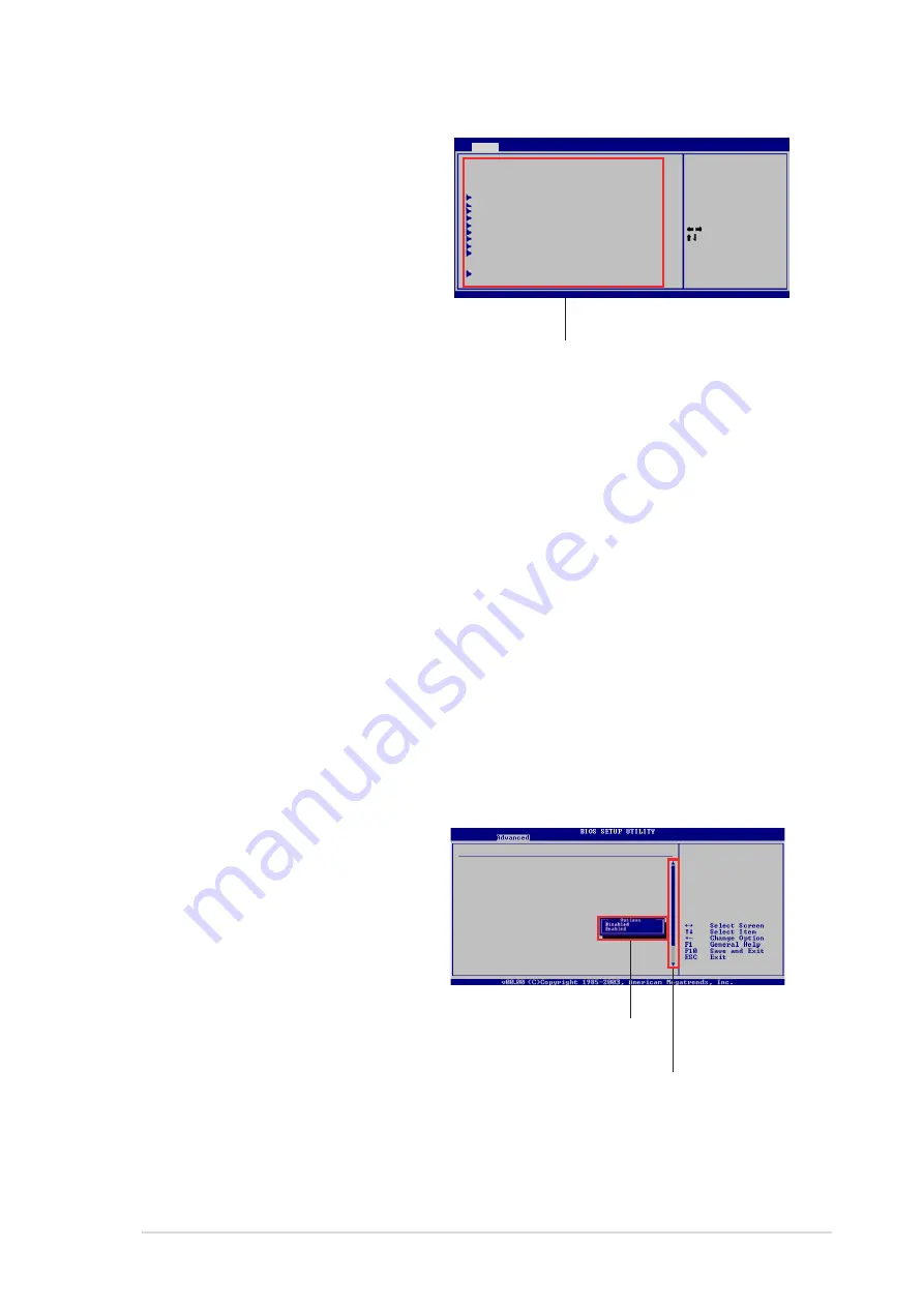
4.2.8

4.2.8

4.2.8

4.2.8

4.2.8

Scroll bar

Scroll bar

Scroll bar

Scroll bar

Scroll bar

A scroll bar appears on the right
side of a menu screen when there
are items that do not fit on the
screen. Press the
Up/Down arrow keys or <Page
Up> /<Page Down> keys to
display the other items on the
screen.

4.2.9

4.2.9

4.2.9

4.2.9

4.2.9

General help

General help

General help

General help

General help

At the top right corner of the menu screen is a brief description of the
selected item.

M a i n   m e n u   i t e m s

M a i n   m e n u   i t e m s

M a i n   m e n u   i t e m s

M a i n   m e n u   i t e m s

M a i n   m e n u   i t e m s

Use [ENTER], [TAB],
or [SHIFT-TAB] to
select a field.

Use  [+] or [-] to
configure system
time.

Select Screen
Select Item

+-

Change Field

Tab

Select Field

F1

General Help

F10

Save and Exit

ESC

Exit

System Time

[10:55:25]

System Date

[Mon 09/22/2005]

Legacy Diskette A

[1.44M, 3.5 in.]

Language

[English]

Primary IDE Master

[ST320410A]

Primary IDE Slave

[ASUS CD-S520/A]

Secondary IDE Master[Not Detected]

Secondary IDE Slave [Not Detected]

First SATA Device

[Not Detected]

Second SATA Device

[Not Detected]

Third SATA Device

[Not Detected]

Fourth SATA Device

[Not Detected]

IDE Configuration

[Not Detected]

System Information

BIOS SETUP UTILITY

Main

Advanced

Power

Boot

Exit

v02.58 (C)Copyright 1985-2004,American Megatrends, Inc.

Advanced PCI/PnP Settings

WARNING: Setting wrong values in
below sections may cause system to
malfunction.

Plug And Play O/S

[No]

PCI Latency Timer

[64]

Allocate IRQ to PCI VGA

[Yes]

Palette Snooping

[Disabled]

PCI IDE BusMaster

[Enabled]

S c r o l l   b a r

S c r o l l   b a r

S c r o l l   b a r

S c r o l l   b a r

S c r o l l   b a r

P o p - u p   w i n d o w

P o p - u p   w i n d o w

P o p - u p   w i n d o w

P o p - u p   w i n d o w

P o p - u p   w i n d o w

Summary of Contents for P5N32-SLI SE DELUXE

Page 1: ...Motherboard P5N32 SLI Deluxe ...

Page 2: ...ber of the product is defaced or missing ASUS PROVIDES THIS MANUAL AS IS WITHOUT WARRANTY OF ANY KIND EITHER EXPRESS OR IMPLIED INCLUDING BUT NOT LIMITED TO THE IMPLIED WARRANTIES OR CONDITIONS OF MERCHANTABILITY OR FITNESS FOR A PARTICULAR PURPOSE IN NO EVENT SHALL ASUS ITS DIRECTORS OFFICERS EMPLOYEES OR AGENTS BE LIABLE FOR ANY INDIRECT SPECIAL INCIDENTAL OR CONSEQUENTIAL DAMAGES INCLUDING DAMA...

Page 3: ... information Chapter 2 Hardware information Chapter 2 Hardware information 2 1 Before you proceed 2 1 2 2 Motherboard overview 2 2 2 2 1 Placement direction 2 2 2 2 2 Screw holes 2 2 2 2 3 ASUS Stack Cool 2 2 3 2 2 4 Motherboard layout 2 4 2 2 5 Layout contents 2 5 2 3 Central Processing Unit CPU 2 7 2 3 1 Installing the CPU 2 8 2 3 2 Installing the CPU heatsink and fan 2 10 2 3 3 Uninstalling the...

Page 4: ...dual function power switch 3 2 Chapter 4 BIOS setup Chapter 4 BIOS setup Chapter 4 BIOS setup Chapter 4 BIOS setup Chapter 4 BIOS setup 4 1 Managing and updating your BIOS 4 1 4 1 1 Creating a bootable floppy disk 4 1 4 1 2 AFUDOS utility 4 2 4 1 3 ASUS CrashFree BIOS 2 utility 4 5 4 1 4 ASUS EZ Flash utility 4 7 4 1 5 ASUS Update utility 4 8 4 2 BIOS setup program 4 11 4 2 1 BIOS menu screen 4 12...

Page 5: ...5 2 Repost Video on S3 Resume 4 34 4 5 3 ACPI 2 0 Support 4 35 4 5 4 ACPI APIC Support 4 35 4 5 5 APM Configuration 4 35 4 5 6 Hardware Monitor 4 37 4 6 Boot menu 4 39 4 6 1 Boot Device Priority 4 39 4 6 2 Boot Settings Configuration 4 40 4 6 3 Security 4 41 4 7 Exit menu 4 43 Chapter 5 Software support Chapter 5 Software support Chapter 5 Software support Chapter 5 Software support Chapter 5 Soft...

Page 6: ...NVIDIA Chapter 6 NVIDIA Chapter 6 NVIDIA Chapter 6 NVIDIA Chapter 6 NVIDIA SLI technology support SLI technology support SLI technology support SLI technology support SLI technology support 6 1 Overview 6 1 6 2 Dual graphics card setup 6 2 6 2 1 Installing SLI ready graphics cards 6 2 6 2 2 Installing the device drivers 6 5 6 2 3 Enabling the multi GPU feature in Windows 6 5 Appendix CPU features ...

Page 7: ...e user is encouraged to try to correct the interference by one or more of the following measures Reorient or relocate the receiving antenna Increase the separation between the equipment and receiver Connect the equipment to an outlet on a circuit different from that to which the receiver is connected Consult the dealer or an experienced radio TV technician for help Canadian Department of Communica...

Page 8: ... correct voltage in your area If you are not sure about the voltage of the electrical outlet you are using contact your local power company If the power supply is broken do not try to fix it by yourself Contact a qualified service technician or your retailer Operation safety Operation safety Operation safety Operation safety Operation safety Before installing the motherboard and adding devices on ...

Page 9: ...ed descriptions of the BIOS parameters are also provided Chapter 5 Software support Chapter 5 Software support Chapter 5 Software support Chapter 5 Software support Chapter 5 Software support This chapter describes the contents of the support CD that comes with the motherboard package Chapter 6 NVIDIA Chapter 6 NVIDIA Chapter 6 NVIDIA Chapter 6 NVIDIA Chapter 6 NVIDIA SLI technology support SLI te...

Page 10: ...he Enter or Return key Key1 Key2 Key3 If you must press two or more keys simultaneously the key names are linked with a plus sign Example Ctrl Alt D Command Means that you must type the command exactly as shown then supply the required item or value enclosed in brackets Example At the DOS prompt type the command line afudos i filename afudos iP5N32SP ROM DANGER WARNING DANGER WARNING DANGER WARNIN...

Page 11: ...rce 4 SLI Intel Edition Southbridge NVIDIA nForce 4 SLI 1066 800 533 MHz Dual channel memory architecture 4 x 240 pin DIMM sockets support up to 16 GB unbuffered non ECC DDR2 667 533 MHz memory modules Supports the NVIDIA Dynamic Adaptive Speculative Preprocessor DASP and QuickSync feature 2 x PCI Express x16 slots with Scalable Link Interface SLI support at full x16 x16 mode 1 x PCI Express x4 sl...

Page 12: ...uner ASUS PEG Link automatic performance tuning for single dual graphics cards ASUS CPU Lock Free ASUS AI Booster Utility Precision Tweaker supports DIMM voltage 8 step DRAM voltage control Core voltage Adjustable CPU voltage at 0 0125 V increment Stepless Frequency Selection SFS allows FSB tuning up to 1600 MHz at 1 MHz increment depending on CPU frequency Memory tuning from 400 MHz to 1600 MHz P...

Page 13: ... language BIOS 8 Mb Flash ROM AMI BIOS PnP DMI2 44 SM BIOS 2 33 WfM2 0 1 x Parallel port 2 x LAN RJ 45 ports 4 x USB 2 0 ports 5 x USB ports optional for Wi Fi edition 1 x Wireless LAN port IEEE 802 11 b g optional 1 x External Serial ATA port 1 x Optical S PDIF Out port 1 x Coaxial S PDIF Out port 1 x PS 2 keyboard port purple 1 x PS 2 mouse port green 8 channel audio ports 1 x Floppy disk drive ...

Page 14: ...nts contents contents contents Form Factor Form Factor Form Factor Form Factor Form Factor ATX power supply with 24 pin and 8 pin 12 V plugs ATX 12 V 2 0 compliant Device drivers ASUS PC Probe II ASUS Update ASUS AI Booster NVIDIA NV Firewall NVIDIA NV RAID NVIDIA NV RIS Remote Installation Service Anti Virus Utility OEM version ATX form factor 12 in x 9 6 in 30 5 cm x 24 5 cm Specifications are s...

Page 15: ...1 Product introduction This chapter describes the motherboard features and the new technologies it supports ...

Page 16: ...ASUS P5N32 SLI Deluxe ASUS P5N32 SLI Deluxe ASUS P5N32 SLI Deluxe ASUS P5N32 SLI Deluxe ASUS P5N32 SLI Deluxe Chapter summary 1 1 1 Welcome 1 1 1 2 Package contents 1 1 1 3 Special features 1 2 ...

Page 17: ... items in your package with the list below 1 2 Package contents Check your motherboard package for the following items If any of the above items is damaged or missing contact your retailer Motherboard Motherboard Motherboard Motherboard Motherboard ASUS P5N32 SLI Deluxe motherboard I O modules I O modules I O modules I O modules I O modules 1 x IEEE1394a module 1 x Serial port module 1 x 2 port US...

Page 18: ...y allows two graphics processing units GPUs in a single system This technology takes advantage of the PCI Express bus architecture and features intelligent hardware and software solutions that allows multiple GPUs to work together and achieve exceptional graphics performance See Chapter 6 for details Intel Intel Intel Intel Intel Dual Core Technology CPU support Dual Core Technology CPU support Du...

Page 19: ...n receiving the data from memory and sending it to the CPU for all FSB and memory speeds NVIDIA NVIDIA NVIDIA NVIDIA NVIDIA DASP 3 0 DASP 3 0 DASP 3 0 DASP 3 0 DASP 3 0 The NVIDIA Dynamic Adaptive Speculative Preprocessor DASP 3 0 comes with sophisticated data pre fetch algorithms in preprocessors that are tasked to track data threads and pre fetch appropriate data for improved performance Built i...

Page 20: ...e 2 28 for details Wireless LAN solution Wireless LAN solution Wireless LAN solution Wireless LAN solution Wireless LAN solution optional optional optional optional optional The motherboard comes with the Realtek RTL8187L LAN controller for the onboard wireless LAN module that supports IEEE 802 11 b g standards allowing data transmission of up to 54 Mbps using the 2 4 GHz 5 GHz frequency band ASUS...

Page 21: ... IEEE 1394a support The IEEE 1394a interface provides high speed and flexible PC connectivity to a wide range of peripherals and devices compliant to the IEEE 1394a standard The IEEE 1394a interface allows up to 400 Mbps transfer rates through simple low cost high bandwidth asynchronous real time data interfacing between computers peripherals and consumer electronic devices such as camcorders VCRs...

Page 22: ...s ASUS AI Life features Serial ATA II and SATA On The Go Serial ATA II and SATA On The Go Serial ATA II and SATA On The Go Serial ATA II and SATA On The Go Serial ATA II and SATA On The Go The motherboard supports the Serial ATA 3 Gb s technology through the Silicon Image Serial ATA interfaces and the NVIDIA SLI Intel Edition chipset The Serial ATA 3 Gb s specification provides twice the bandwidth...

Page 23: ... 27 and 5 13 for details Fanless Design Fanless Design Fanless Design Fanless Design Fanless Design The ASUS fanless design allows multi directional heat flow from major thermal sources in the motherboard to lower overall system temperature resulting in quieter operation and longer system life PEG Link Mode for two graphics cards PEG Link Mode for two graphics cards PEG Link Mode for two graphics ...

Page 24: ...ti language BIOS ASUS Multi language BIOS ASUS Multi language BIOS ASUS Multi language BIOS The multi language BIOS allows you to select the language of your choice from the available options The localized BIOS menus allow easier and faster configuration See page 4 14 for details ASUS MyLogo2 ASUS MyLogo2 ASUS MyLogo2 ASUS MyLogo2 ASUS MyLogo2 This new feature present in the motherboard allows you...

Page 25: ... Hardware information This chapter lists the hardware setup procedures that you have to perform when installing system components It includes description of the jumpers and connectors on the motherboard ...

Page 26: ...N32 SLI Deluxe ASUS P5N32 SLI Deluxe ASUS P5N32 SLI Deluxe Chapter summary 2 2 1 Before you proceed 2 1 2 2 Motherboard overview 2 2 2 3 Central Processing Unit CPU 2 7 2 4 System memory 2 15 2 5 Expansion slots 2 22 2 6 Jumper 2 26 2 7 Connectors 2 27 ...

Page 27: ...ing them due to static electricity Hold components by the edges to avoid touching the ICs on them Whenever you uninstall any component place it on a grounded antistatic pad or in the bag that came with the component Before you install or remove any component ensure Before you install or remove any component ensure Before you install or remove any component ensure Before you install or remove any c...

Page 28: ...2 2 1 2 2 1 2 2 1 2 2 1 2 2 1 Placement direction Placement direction Placement direction Placement direction Placement direction When installing the motherboard make sure that you place it into the chassis in the correct orientation The edge with external ports goes to the rear part of the chassis as indicated in the image below 2 2 2 2 2 2 2 2 2 2 2 2 2 2 2 Screw holes Screw holes Screw holes Sc...

Page 29: ...3 2 2 3 ASUS Stack Cool 2 ASUS Stack Cool 2 ASUS Stack Cool 2 ASUS Stack Cool 2 ASUS Stack Cool 2 The motherboard comes with the ASUS Stack Cool 2 cooling solution that lowers the temperature of critical heat generating components The motherboard uses a special design on the printed circuit board PCB to dissipate heat that critical components generate ...

Page 30: ..._A2 64 bit 240 pin module DDR2 DIMM_B2 64 bit 240 pin module PWR_FAN LAN2_USB34 IE1394_1 CHA_FAN2 FLOPPY Super I O 8Mb BIOS TSB43AB22A PS 2KBMS T Mouse B Keyboard PARALLEL PORT SPDIF_O SPDIF_O2 LAN1_USB12 CD ACL850 PCIEX16_1 PCIEX1_1 PCIEX1_2 PCIEX16_2 PCI1 PCI2 Marvell PHY CLRTC USB78 USB56 SATA3 SATA4 SATA2 SATA1 SATA_RAID1 ESATA nVidia nForce 4 SLI SB_PWR EATXPWR PRI_IDE CR2032 3V Lithium Cell ...

Page 31: ...a g e P a g e 1 Clear RTC RAM 3 pin CLRTC 2 26 Rear panel connectors Rear panel connectors Rear panel connectors Rear panel connectors Rear panel connectors P a g e P a g e P a g e P a g e P a g e 1 PS 2 mouse port green 2 27 2 Parallel port 2 27 3 Side Speaker Out port black 2 27 4 Rear Speaker Out port gray 2 27 5 Line In port light blue 2 27 6 Line Out port lime 2 27 7 LAN 2 RJ 45 2 28 8 LAN 1 ...

Page 32: ...audio connector 4 pin CD 2 34 7 Auxiliary audio connector 4 pin AUX 2 34 8 USB connectors 10 1 pin USB56 USB78 2 34 9 Front panel audio connector 10 1 pin FP_AUDIO 2 35 10 IEEE 1394 port connectors 10 1 pin IE1394_1 IE1394_2 2 35 11 GAME MIDI port connector 16 1 pin GAME 2 36 12 Serial port connector 10 1 pin COM1 2 36 13 CPU Chassis Northbridge and Power Fan connectors 4 pin CPU_FAN 3 pin PWR_FAN...

Page 33: ... will shoulder the cost of repair only if the damage is shipment transit related Keep the cap after installing the motherboard ASUS will process Return Merchandise Authorization RMA requests only if the motherboard comes with the cap on the LGA775 socket The product warranty does not cover damage to the socket contacts resulting from incorrect CPU installation removal or misplacement loss incorrec...

Page 34: ...with your thumb A then move it to the left B until it is released from the retention tab Retention tab Retention tab Retention tab Retention tab Retention tab Load lever Load lever Load lever Load lever Load lever This side of the This side of the This side of the This side of the This side of the socket box should socket box should socket box should socket box should socket box should face you fa...

Page 35: ...nology EM64T Enhanced Intel SpeedStep Technology EIST and Hyper Threading Technology Refer to the Appendix for more information on these CPU features 4 Lift the load plate with your thumb and forefinger to a 100º angle A then push the PnP cap from the load plate window to remove B 5 Position the CPU over the socket making sure that the gold triangle is on the bottom left corner of the socket The s...

Page 36: ...therboard Narrow end Narrow end Narrow end Narrow end Narrow end of the groove of the groove of the groove of the groove of the groove When you buy a boxed Intel processor the package includes the CPU fan and heatsink assembly If you buy a CPU separately make sure that you use only Intel certified multi directional heatsink and fan Your Intel LGA775 processor heatsink and fan assembly comes in a p...

Page 37: ...tsink and fan assembly in place B B A A A A B B Do not forget to connect the CPU fan connector Hardware monitoring errors can occur if you fail to plug this connector The retention module of some third party CPU heatsink and fan can interfere with chipset components at the bottom of the board Before purchasing a separate CPU heatsink and fan make sure that it will not interfere with the chipset co...

Page 38: ...k and fan Uninstalling the CPU heatsink and fan Uninstalling the CPU heatsink and fan Uninstalling the CPU heatsink and fan To uninstall the CPU heatsink and fan 1 Disconnect the CPU fan cable from the connector on the motherboard 2 Rotate each fastener counterclockwise 3 Pull up two fasteners at a time in a diagonal sequence to disengage the heatsink and fan assembly from the motherboard B B A A ...

Page 39: ...orientation when reinstalling The narrow end of the groove should point outward after resetting The photo shows the groove shaded for emphasis Narrow end of the groove Narrow end of the groove Narrow end of the groove Narrow end of the groove Narrow end of the groove Refer to the documentation in the boxed or stand alone CPU fan package for detailed information on CPU fan installation ...

Page 40: ...water cooler Installing the optional fan with an active CPU cooler will interfere with the airflow and destabilize the system 1 Position the fan above the pipe and heatsink assembly 2 Fit the grooved edge to the heatsink 3 Carefully push down the fan until it snugly fits the heatsink then connect the fan cables 4 The above photo shows the fans installed on the motherboard Plug the optional fan cab...

Page 41: ... DDR DIMM DDR2 DIMMs are notched differently to prevent installation on a DDR DIMM socket The figure illustrates the location of the DDR2 DIMM sockets Channel Channel Channel Channel Channel S o c k e t s S o c k e t s S o c k e t s S o c k e t s S o c k e t s Channel A Channel A Channel A Channel A Channel A DIMM_A1 and DIMM_A2 DIMM_A1 and DIMM_A2 DIMM_A1 and DIMM_A2 DIMM_A1 and DIMM_A2 DIMM_A1 a...

Page 42: ... into the DIMM sockets If you installed four 1 GB memory modules the system may detect less than 3 GB of total memory because of address space allocation for other critical functions This limitation applies to Windows XP 32 bit version operating system since it does not support Physical Address Extension PAE If you installed Windows XP 32 bit version operating system we recommend that you install ...

Page 43: ...6 MB MICRON MT8HTF3264AY 667B6 SS 5FB42D9DPN 256 MB Infineon HYS64T32000HU 3S A SS HYB18T512160AF 3S 512 MB Infineon HYS64T64000HU 3S A SS HYB18T512800AF3S 1024 MB Infineon HYS64T128020HU 3S A DS HYB18T512800AF3S 256 MB Infineon HYS72T32000HU 3S A SS HYB18T256800AF3S ECC 512 MB Infineon HYS72T64000HU 3S A SS HYB18T512800AF3S ECC 1024 MB Infineon HYS72T128020HU 3S A DS HYB18T512800AF3S ECC 512 MB H...

Page 44: ... C Supports four modules inserted into the yellow and black slots as two pairs of Dual channel memory configuration Visit the ASUS website for the latest DDR2 667 MHz QVL S i z e S i z e S i z e S i z e S i z e V e n d o r V e n d o r V e n d o r V e n d o r V e n d o r P a r t N o P a r t N o P a r t N o P a r t N o P a r t N o B r a n d B r a n d B r a n d B r a n d B r a n d Side s Side s Side ...

Page 45: ...PIDA EBE51UD8ABFA 5C E SS E5108AB 5C E 1024 MB ELPIDA EBE11UD8ABFA 5C E DS E5108AB 5C E 2048 MB ELPIDA EBE21EE8AAFA 5C E DS E1108AA 5C E 256 MB CORSAIR VS256MB533D2 SS MIII0051832M8CEC 512 MB CORSAIR VS512MB533D2 DS MI110052432M8CEC 256 MB Apacer 78 81077 420 SS E5116AB 5C E 256 MB CENTURY 25V6S8SSD5F4 K43 SS K4T56083QF GCD5 512 MB CENTURY 25V2H8EL5CB4 J43 SS E5108AB 5C E 1024 MB CENTURY 25V0H8EL5...

Page 46: ...MB PQI MEAB 323LA DS 64MX8D2 E 512 MB PQI MEAB 423LA SS 64MX8D2 E 512 MB TwinMOS 8D 22JB5 K2T SS K4T51083QB GCD5 512 MB Transcend TS64MLQ64V5J SS K4T51083QB GCD5 1024 MB Transcend TS128MLQ64V5J DS K4T51083QB GCD5 256 MB SimpleTech SVM 42DR2 256 SS 858S032F25A 512 MB SimpleTech SVM 42DR2 512 DS 858S064F25A 512 MB MDT M512 533 8 SS 18D51280D 3 70S20 1024 MB MDT M924 533 16 DS 18D51280D 3 70448 S i d...

Page 47: ...erly seated 2 4 4 2 4 4 2 4 4 2 4 4 2 4 4 Removing a DIMM Removing a DIMM Removing a DIMM Removing a DIMM Removing a DIMM To remove a DIMM 1 Simultaneously press the retaining clips outward to unlock the DIMM 2 Remove the DIMM from the socket A DDR2 DIMM is keyed with a notch so that it fits in only one direction Do not force a DIMM into a socket to avoid damaging the DIMM The DDR2 DIMM sockets do...

Page 48: ... and press firmly until the card is completely seated on the slot 5 Secure the card to the chassis with the screw you removed earlier 6 Replace the system cover 2 5 2 2 5 2 2 5 2 2 5 2 2 5 2 Configuring an expansion card Configuring an expansion card Configuring an expansion card Configuring an expansion card Configuring an expansion card After installing the expansion card configure the it by adj...

Page 49: ...Time Clock 9 4 IRQ holder for PCI steering 10 5 IRQ holder for PCI steering 11 6 IRQ holder for PCI steering 12 7 PS 2 Compatible Mouse Port 13 8 Numeric Data Processor 14 9 Primary IDE Channel 15 10 Secondary IDE Channel These IRQs are usually available for ISA or PCI devices IRQ assignments for this motherboard IRQ assignments for this motherboard IRQ assignments for this motherboard IRQ assignm...

Page 50: ...gure below for the location of the slots 2 5 6 2 5 6 2 5 6 2 5 6 2 5 6 PCI Express x4 slot PCI Express x4 slot PCI Express x4 slot PCI Express x4 slot PCI Express x4 slot This motherboard supports PCI Express x4 network cards SCSI cards and other cards that comply with the PCI Express specifications Refer to the figure below for the location of the slot PCI Express x16 slot PCI Express x16 slot PC...

Page 51: ...omply with the PCI Express specifications The figure shows two graphics card installed on the PCI Express x16 slots See Chapter 6 for details on the SLI technology feature In Single Card mode we recommend that you use the blue slot for PCI Express x16 graphics cards In SLI mode the PCI Express x16 slots work at the full bandwidth of PCI Express x16 on each slot for a combined bandwidth of x32 Inst...

Page 52: ...ove the onboard battery 3 Move the jumper cap from pins 1 2 default to pins 2 3 Keep the cap on pins 2 3 for about 5 10 seconds then move the cap back to pins 1 2 4 Reinstall the battery 5 Plug the power cord and turn ON the computer 6 Hold down the Del key during the boot process and enter BIOS setup to re enter data Except when clearing the RTC RAM never remove the cap on CLRTC jumper default po...

Page 53: ... light blue Line In port light blue This port connects the tape CD DVD player or other audio sources 6 6 6 6 6 Line Out port lime Line Out port lime Line Out port lime Line Out port lime Line Out port lime This port connects a headphone or a speaker In 4 channel 6 channel and 8 channel configuration the function of this port becomes Front Speaker Out Audio 2 4 6 or 8 channel configuration Audio 2 ...

Page 54: ... L i n k A c t i v i t y L i n k A c t i v i t y L i n k A c t i v i t y L i n k S p e e d L E D S p e e d L E D S p e e d L E D S p e e d L E D S p e e d L E D D e s c r i p t i o n D e s c r i p t i o n D e s c r i p t i o n D e s c r i p t i o n D e s c r i p t i o n DNR DNR Soft off Mode DNR DNR During Power ON OFF DNR DNR 100 Mbps connection DNR DNR 1 Gbps connection 7 7 7 7 7 LAN 2 RJ 45 por...

Page 55: ...ble for connecting USB 2 0 devices 13 13 13 13 13 USB 2 0 ports 3 and 4 USB 2 0 ports 3 and 4 USB 2 0 ports 3 and 4 USB 2 0 ports 3 and 4 USB 2 0 ports 3 and 4 These two 4 pin Universal Serial Bus USB ports are available for connecting USB 2 0 devices 14 14 14 14 14 Microphone port pink Microphone port pink Microphone port pink Microphone port pink Microphone port pink This port connects a microph...

Page 56: ... connector at the back of the floppy disk drive Pin 5 on the connector is removed to prevent incorrect cable connection when using a FDD cable with a covered Pin 5 17 17 17 17 17 Optical S PDIF Out port Optical S PDIF Out port Optical S PDIF Out port Optical S PDIF Out port Optical S PDIF Out port This port connects an external audio output device via an optical S PDIF cable 18 18 18 18 18 Coaxial...

Page 57: ...DE slave device optical drive hard disk drive and a gray connector for an Ultra DMA 133 100 66 IDE master device hard disk drive If you install two hard disk drives you must configure the second drive as a slave device by setting its jumper accordingly Refer to the hard disk documentation for the jumper settings Pin 20 on the IDE connector is removed to match the covered hole on the Ultra DMA cabl...

Page 58: ... compatible with Serial ATA 1 5Gb s specification If you installed Serial ATA hard disk drives you can create a RAID 0 RAID 1 RAID 0 1 RAID 5 or JBOD configuration through the onboard NVIDIA nForce 4 SLI RAID controller Refer to section 5 4 2 NVIDIA RAID configurations for details on how to set up Serial ATA RAID configurations The RAID function of these connectors is set to Disabled by default If...

Page 59: ...gurations If you intend to create a RAID configuration using this connector set the Silicon 3132 Controller Silicon 3132 Controller Silicon 3132 Controller Silicon 3132 Controller Silicon 3132 Controller item in the BIOS to RAID Mode See section 4 4 6 Onboard Devices Configuration for details Before creating a RAID set using Serial ATA hard disks make sure that you have connected the Serial ATA si...

Page 60: ... connectors 10 1 pin USB56 USB78 USB connectors 10 1 pin USB56 USB78 USB connectors 10 1 pin USB56 USB78 These connectors are for USB 2 0 ports Connect the USB GAME module cable to any of these connectors then install the module to a slot opening at the back of the system chassis These USB connectors comply with USB 2 0 specification that supports up to 480 Mbps connection speed Never connect a 13...

Page 61: ... cable USB cable USB cable USB cable USB cable to the IEEE 1394a connectors Doing so will damage the motherboard 7 7 7 7 7 Front panel audio connector 10 1 pin FP_AUDIO Front panel audio connector 10 1 pin FP_AUDIO Front panel audio connector 10 1 pin FP_AUDIO Front panel audio connector 10 1 pin FP_AUDIO Front panel audio connector 10 1 pin FP_AUDIO This connector is for a chassis mounted front p...

Page 62: ...to a slot opening at the back of the system chassis The GAME MIDI port connects a joystick or game pad for playing games and MIDI devices for playing or editing audio files 10 10 10 10 10 Serial port connector 10 1 pin COM1 Serial port connector 10 1 pin COM1 Serial port connector 10 1 pin COM1 Serial port connector 10 1 pin COM1 Serial port connector 10 1 pin COM1 This connector is for a serial C...

Page 63: ...s support cooling fans of 350 mA 2000 mA 24 W max or a total of 1 A 3 48 A 41 76 W max at 12V Connect the fan cables to the fan connectors on the motherboard making sure that the black wire of each cable matches the ground pin of the connector Only the CPU_FAN and CHA_FAN1 connectors support the ASUS Q Fan 2 feature Do not forget to connect the fan cables to the fan connectors Insufficient air flo...

Page 64: ...pin CHASSIS Chassis intrusion connector 4 1 pin CHASSIS Chassis intrusion connector 4 1 pin CHASSIS This connector is for a chassis mounted intrusion detection sensor or switch Connect one end of the chassis intrusion sensor or switch cable to this connector The chassis intrusion sensor or switch sends a high level signal to this connector when a chassis component is removed or replaced The signal...

Page 65: ...2 V V 2 1 2 V V 2 1 2 V V 2 1 2 V V 2 1 2 V V 1 1 2 V V 1 1 2 V V 1 1 2 V V 1 1 2 V V 1 5 V 5 V 5 V 5 V 5 V 3 3 V 3 3 V 3 3 V 3 3 V 3 3 V 4 p i n 4 p i n 4 p i n 4 p i n 4 p i n 2 4 p i n 2 4 p i n 2 4 p i n 2 4 p i n 2 4 p i n Io_max A 13 22 16 61 16 14 4 17 Io_rms A 8 18 9 43 12 475 3 566 Vout V 12 12 5 3 3 Po_max W 158 64 199 32 80 7 13 761 TOTAL PSU Po_max W 4 5 2 4 2 1 4 5 2 4 2 1 4 5 2 4 2 1...

Page 66: ...n IDE_LED Hard disk drive activity LED Red 2 pin IDE_LED Hard disk drive activity LED Red 2 pin IDE_LED Hard disk drive activity LED Red 2 pin IDE_LED Hard disk drive activity LED Red 2 pin IDE_LED This 2 pin connector is for the HDD Activity LED Connect the HDD Activity LED cable to this connector The IDE LED lights up or flashes when data is read from or written to the HDD 1 2 V V 2 1 2 V V 2 1 ...

Page 67: ...utton ATX power button soft off button ATX power button soft off button ATX power button soft off button Light Green 2 pin PWR Light Green 2 pin PWR Light Green 2 pin PWR Light Green 2 pin PWR Light Green 2 pin PWR This connector is for the system power button Pressing the power button turns the system on or puts the system in sleep or soft off mode depending on the BIOS settings Pressing the powe...

Page 68: ...2 42 2 42 2 42 2 42 2 42 Chapter 2 Hardware information Chapter 2 Hardware information Chapter 2 Hardware information Chapter 2 Hardware information Chapter 2 Hardware information ...

Page 69: ...3 Powering up This chapter describes the power up sequence the vocal POST messages and ways of shutting down the system ...

Page 70: ...ASUS P5N32 SLI Deluxe ASUS P5N32 SLI Deluxe ASUS P5N32 SLI Deluxe ASUS P5N32 SLI Deluxe ASUS P5N32 SLI Deluxe Chapter summary 3 3 1 Starting up for the first time 3 1 3 2 Powering off the computer 3 2 ...

Page 71: ...power the system power LED on the system front panel case lights up For systems with ATX power supplies the system LED lights up when you press the ATX power button If your monitor complies with green standards or if it has a power standby feature the monitor LED may light up or switch between orange and green after the system LED turns on The system then runs the power on self tests or POST While...

Page 72: ...dows shuts down If you are using Windows XP 1 Click the Start Start Start Start Start button then select Turn Off Computer Turn Off Computer Turn Off Computer Turn Off Computer Turn Off Computer 2 Click the Turn Off Turn Off Turn Off Turn Off Turn Off button to shut down the computer 3 The power supply should turn off after Windows shuts down 3 2 2 3 2 2 3 2 2 3 2 2 3 2 2 Using the dual function p...

Page 73: ...4 BIOS setup This chapter tells how to change the system settings through the BIOS Setup menus Detailed descriptions of the BIOS parameters are also provided ...

Page 74: ...S P5N32 SLI Deluxe ASUS P5N32 SLI Deluxe ASUS P5N32 SLI Deluxe Chapter summary 4 4 1 Managing and updating your BIOS 4 1 4 2 BIOS setup program 4 11 4 3 Main menu 4 14 4 4 Advanced menu 4 20 4 5 Power menu 4 34 4 6 Boot menu 4 39 4 7 Exit menu 4 43 ...

Page 75: ...ppy disk Creating a bootable floppy disk Creating a bootable floppy disk 1 Do either one of the following to create a bootable floppy disk DOS environment a Insert a 1 44MB floppy disk into the drive b At the DOS prompt type format A S then press Enter Windows XP environment a Insert a 1 44 MB floppy disk to the floppy disk drive b Click Start Start Start Start Start from the Windows desktop then ...

Page 76: ...al drive c Click Start Start Start Start Start then select Run Run Run Run Run d In the Open Open Open Open Open field type D bootdisk makeboot a assuming that D is your optical drive letter e Press Enter then follow screen instructions to continue 2 Copy the original or the latest motherboard BIOS file to the bootable floppy disk Main filename Main filename Main filename Main filename Main filena...

Page 77: ...S utility afudos exe from the motherboard support CD to the bootable floppy disk you created earlier 3 Boot the system in DOS mode then at the prompt type afudos i filename where filename is the latest or the original BIOS file on the bootable floppy disk Updating the BIOS file Updating the BIOS file Updating the BIOS file Updating the BIOS file Updating the BIOS file To update the BIOS file using...

Page 78: ...rn off power during flash BIOS Reading file done Reading flash done Advance Check Erasing flash done Writing flash 0x0008CC00 9 4 The utility verifies the file and starts updating the BIOS Do not shut down or reset the system while updating the BIOS to prevent system boot failure A afudos iP5N32SD rom AMI Firmware Update Utility Version 1 19 ASUS V2 07 03 11 24BB Copyright C 2002 American Megatren...

Page 79: ...isk To recover the BIOS from a floppy disk 1 Turn on the system 2 Insert the floppy disk with the original or updated BIOS file to the floppy disk drive 3 The utility displays the following message and automatically checks the floppy disk for the original or updated BIOS file Bad BIOS checksum Starting BIOS recovery Checking for floppy 4 Restart the system after the utility completes the updating ...

Page 80: ...drive then turn on the system 2 Insert the support CD to the optical drive 3 The utility displays the following message and automatically checks the floppy disk for the original or updated BIOS file 4 Restart the system after the utility completes the updating process DO NOT shut down or reset the system while updating the BIOS Doing so can cause system boot failure Bad BIOS checksum Starting BIOS...

Page 81: ...D ROM P5N32SD ROM P5N32SD ROM P5N32SD ROM P5N32SD ROM 2 Save the BIOS file to a floppy disk then restart the system 3 Press Alt F2 during POST to display the following EZFlash starting BIOS update Checking for floppy 4 Insert the floppy disk that contains the BIOS file to the floppy disk drive When the correct BIOS file is found EZ Flash performs the BIOS update process and automatically reboots t...

Page 82: ... ASUS Update utility is copied to your system 4 1 5 4 1 5 4 1 5 4 1 5 4 1 5 ASUS Update utility ASUS Update utility ASUS Update utility ASUS Update utility ASUS Update utility The ASUS Update is a utility that allows you to manage save and update the motherboard BIOS in Windows environment The ASUS Update utility allows you to Save the current BIOS file Download the latest BIOS file from the Inter...

Page 83: ...gh the Internet Updating the BIOS through the Internet To update the BIOS through the Internet 1 Launch the ASUS Update utility from the Windows desktop by clicking Start Start Start Start Start Programs Programs Programs Programs Programs ASUS ASUS ASUS ASUS ASUS ASUSUpdate ASUSUpdate ASUSUpdate ASUSUpdate ASUSUpdate ASUSUpdate ASUSUpdate ASUSUpdate ASUSUpdate ASUSUpdate The ASUS Update main wind...

Page 84: ...SUSUpdate ASUSUpdate ASUSUpdate ASUSUpdate ASUSUpdate ASUSUpdate ASUSUpdate ASUSUpdate The ASUS Update main window appears 2 Select Update BIOS from a Update BIOS from a Update BIOS from a Update BIOS from a Update BIOS from a file file file file file option from the drop down menu then click Next Next Next Next Next 4 From the FTP site select the BIOS version that you wish to download Click Next ...

Page 85: ...ogram Press Del during the Power On Self Test POST to enter the Setup utility otherwise POST continues with its test routines If you wish to enter Setup after POST restart the system by pressing Ctrl Alt Delete or by pressing the reset button on the system chassis You can also restart by turning the system off and then back on Do this last option only if the first two failed The Setup program is d...

Page 86: ... the navigation keys differ from one screen to another Select Screen Select Item Change Field Tab Select Field F1 General Help F10 Save and Exit ESC Exit v02 58 C Copyright 1985 2004 American Megatrends Inc BIOS SETUP UTILITY Main Advanced Power Boot Exit 4 2 1 4 2 1 4 2 1 4 2 1 4 2 1 BIOS menu screen BIOS menu screen BIOS menu screen BIOS menu screen BIOS menu screen System Time 10 55 25 System D...

Page 87: ...figuration options for that item 4 2 8 4 2 8 4 2 8 4 2 8 4 2 8 Scroll bar Scroll bar Scroll bar Scroll bar Scroll bar A scroll bar appears on the right side of a menu screen when there are items that do not fit on the screen Press the Up Down arrow keys or Page Up Page Down keys to display the other items on the screen 4 2 9 4 2 9 4 2 9 4 2 9 4 2 9 General help General help General help General he...

Page 88: ...K 5 25 in 1 2M 5 25 in 720K 3 5 in 1 44M 3 5 in 2 88M 3 5 in 4 3 4 4 3 4 4 3 4 4 3 4 4 3 4 Language English Language English Language English Language English Language English Allows you to choose the BIOS language version from the options Configuration options Chinese BIG5 Chinese GB Japanese Français German English Refer to section 4 2 1 BIOS menu screen for information on the menu screen items ...

Page 89: ...ically configuring a CD ROM drive Select ARMD ATAPI Removable Media Device if your device is either a ZIP LS 120 or MO drive Configuration options Not Installed Auto CDROM ARMD LBA Large Mode Auto LBA Large Mode Auto LBA Large Mode Auto LBA Large Mode Auto LBA Large Mode Auto Enables or disables the LBA mode Setting to Auto enables the LBA mode if the device supports this mode and if the device wa...

Page 90: ...n Select Item Change Option F1 General Help F10 Save and Exit ESC Exit v02 58 C Copyright 1985 2004 American Megatrends Inc BIOS SETUP UTILITY Main 4 3 6 4 3 6 4 3 6 4 3 6 4 3 6 First Second Third and Fourth SATA Device First Second Third and Fourth SATA Device First Second Third and Fourth SATA Device First Second Third and Fourth SATA Device First Second Third and Fourth SATA Device The BIOS aut...

Page 91: ...iguration options Disabled Auto PIO Mode Auto PIO Mode Auto PIO Mode Auto PIO Mode Auto PIO Mode Auto Selects the PIO mode Configuration options Auto 0 1 2 3 4 DMA Mode Auto DMA Mode Auto DMA Mode Auto DMA Mode Auto DMA Mode Auto Selects the DMA mode Configuration options Auto SWDMA0 SWDMA1 SWDMA2 MWDMA0 MWDMA1 MWDMA2 UDMA0 UDMA1 UDMA2 UDMA3 UDMA4 UDMA5 SMART Monitoring Auto SMART Monitoring Auto ...

Page 92: ...rotect Disabled Hard Disk Write Protect Disabled Allows you to enable or disable the hard disk write protect feature You can use this feature only if you access the device through the BIOS Configuration options Disabled Enabled IDE Detect Time out Sec 35 IDE Detect Time out Sec 35 IDE Detect Time out Sec 35 IDE Detect Time out Sec 35 IDE Detect Time out Sec 35 Selects the time out value for detect...

Page 93: ... Information System Information This menu gives you an overview of the general system specifications The BIOS automatically detects the items in this menu AMI BIOS AMI BIOS AMI BIOS AMI BIOS AMI BIOS Displays the auto detected BIOS information Processor Processor Processor Processor Processor Displays the auto detected CPU specification System Memory System Memory System Memory System Memory Syste...

Page 94: ...rclock Profile Overclock Profile Overclock Profile loads overclocking profiles with optimal parameters for stability when overclocking AI N O S AI N O S AI N O S AI N O S AI N O S The ASUS AI Non delay Overclocking System feature intelligently determines the system load and automatically boosts the performance for the most demanding tasks Take caution when changing the settings of the Advanced men...

Page 95: ...ect Screen Select Item Change Option F1 General Help F10 Save and Exit ESC Exit v02 58 C Copyright 1985 2004 American Megatrends Inc BIOS SETUP UTILITY Advanced Select Screen Select Item Change Option F1 General Help F10 Save and Exit ESC Exit v02 58 C Copyright 1985 2004 American Megatrends Inc BIOS SETUP UTILITY Advanced Performance Options FSB Optimize Mode Disabled Memory Optimize Mode Disable...

Page 96: ... Mode System Clock Mode System Clock Mode System Clock Mode is set to Linked FSB Clock Mhz XXX FSB Clock Mhz XXX FSB Clock Mhz XXX FSB Clock Mhz XXX FSB Clock Mhz XXX Allows you to set the FSB frequency depending on the frequency of the CPU installed Enter the value using the numeric keypad or use the key to adjust the value up to 1600 Any value that is not within this range will not take effect S...

Page 97: ...al allows you to input the values manually Configuration options Auto Manual The following items appear if you set the Memory Timings Memory Timings Memory Timings Memory Timings Memory Timings item to Manual CAS Latency CL Auto CAS Latency CL Auto CAS Latency CL Auto CAS Latency CL Auto CAS Latency CL Auto Configuration options Auto 1 2 6 tRCD Auto tRCD Auto tRCD Auto tRCD Auto tRCD Auto Configur...

Page 98: ...um Down Spread Configuration options Disabled Down Spread SATA Spread Spectrum Disabled Configuration options Disabled Down Spread LDT Spread Spectrum Disabled Configuration options Disabled Center Spread CPU VCore Voltage Auto CPU VCore Voltage Auto CPU VCore Voltage Auto CPU VCore Voltage Auto CPU VCore Voltage Auto Allows the BIOS to automatically enable or allows you to set the CPU VCore Volta...

Page 99: ...tage Auto SB Chipset Voltage Auto Allows you to select the Southbridge chipset voltage Set to Auto for safe mode Configuration options Auto 1 50V 1 60V The following item appears only when the AI Overclocking AI Overclocking AI Overclocking AI Overclocking AI Overclocking item is set to Overclock Profile Overclock Options Overclock 5 Overclock Options Overclock 5 Overclock Options Overclock 5 Over...

Page 100: ...1 controller Configuration options Enabled Disabled USB 2 0 Controller Enabled USB 2 0 Controller Enabled USB 2 0 Controller Enabled USB 2 0 Controller Enabled USB 2 0 Controller Enabled Allows you to enable or disable the USB 2 0 controller Configuration options Enabled Disabled USB Configuration Module Version 2 24 0 11 4 USB Devices Enabled None USB 1 1 Controller Enabled USB 2 0 Controller Ena...

Page 101: ...page 5 12 for details POST Check LAN2 Cable Disabled LAN2 Cable Status Pair Status Length 1 2 Open 0 0M 3 6 Open 0 0M 4 5 Open 0 0MA 7 8 Open 0 0M Check LAN cable during POST Legacy USB Support Auto Legacy USB Support Auto Legacy USB Support Auto Legacy USB Support Auto Legacy USB Support Auto Allows you to enable or disable support for legacy USB devices Setting to Auto allows the system to detec...

Page 102: ...ns Disabled Enabled Execute Disable Function Disabled Execute Disable Function Disabled Execute Disable Function Disabled Execute Disable Function Disabled Execute Disable Function Disabled Allows you to enable or disable the No Execution Page Protection Technology Setting this item to Enabled forces the XD feature flag to always return to zero 0 Configuration options Disabled Enabled Hardware Pre...

Page 103: ...ed Hyper Threading Technology Enabled Allows you to enable or disable the processor Hyper Threading Technology Refer to the Appendix for more information on the Hyper Threading Technology Configuration options Disabled Enabled The following item appears only when you installed an Intel Pentium 4 CPU that supports the Enhanced Intel SpeedStep Technology EIST Intel R SpeedStep Technology Automatic I...

Page 104: ...imary Graphics Adapter PCIE1 PCI PCIE2 Primary Graphics Adapter PCIE1 PCI PCIE2 Primary Graphics Adapter PCIE1 PCI PCIE2 Primary Graphics Adapter PCIE1 PCI PCIE2 Allows selection of the graphics controller to use as primary boot device Configuration options PCIE2 PCI PCIE1 PCIE1 PCI PCIE2 PEG Link Mode Auto PEG Link Mode Auto PEG Link Mode Auto PEG Link Mode Auto PEG Link Mode Auto Sets the PCI Ex...

Page 105: ...abled Enabled Onboard GbE LAN2 Enabled Onboard GbE LAN2 Enabled Onboard GbE LAN2 Enabled Onboard GbE LAN2 Enabled Onboard GbE LAN2 Enabled Allows you to enable or disable the onboard PCI Express Gigabit LAN controller Configuration options Disabled Enabled Onboard LAN2 Boot ROM Disabled This item allows you to enable or disable the PCI Express Gigabit LAN boot ROM This item appears only when the O...

Page 106: ...Parallel Port Address 378 Parallel Port Address 378 Parallel Port Address 378 Parallel Port Address 378 Allows you to select the Parallel Port base addresses Configuration options Disabled 378 278 3BC Parallel Port Mode Normal Parallel Port Mode Normal Parallel Port Mode Normal Parallel Port Mode Normal Parallel Port Mode Normal Allows you to select the Parallel Port mode Configuration options Nor...

Page 107: ...Plug And Play O S No Plug And Play O S No Plug And Play O S No Plug And Play O S No Plug And Play O S No When set to No BIOS configures all the devices in the system When set to Yes and if you install a Plug and Play operating system the operating system configures the Plug and Play devices not required for boot Configuration options No Yes PCI Latency Timer 64 PCI Latency Timer 64 PCI Latency Tim...

Page 108: ... 2 4 5 2 4 5 2 4 5 2 4 5 2 Repost Video on S3 Resume No Repost Video on S3 Resume No Repost Video on S3 Resume No Repost Video on S3 Resume No Repost Video on S3 Resume No Determines whether to invoke VGA BIOS POST on S3 STR resume Configuration options No Yes Suspend Mode Auto Repost Video on S3 Resume No ACPI 2 0 Support No ACPI APIC Support Enabled APM Configuration Hardware Monitor Allocate IR...

Page 109: ...Off Power Button Mode On Off Power Button Mode On Off Allows the system to go into On Off mode or suspend mode when the power button is pressed Configuration options On Off Suspend Restore on AC Power Loss Last State Restore on AC Power Loss Last State Restore on AC Power Loss Last State Restore on AC Power Loss Last State Restore on AC Power Loss Last State When set to Power Off the system goes i...

Page 110: ... Keyboard Disabled Power On By PS 2 Keyboard Disabled Power On By PS 2 Keyboard Disabled Allows you to use specific keys on the keyboard to turn on the system This feature requires an ATX power supply that provides at least 1A on the 5VSB lead Configuration options Disabled Enabled Power On By PS 2 Mouse Disabled Power On By PS 2 Mouse Disabled Power On By PS 2 Mouse Disabled Power On By PS 2 Mous...

Page 111: ...red The onboard hardware monitor automatically detects and displays the CPU fan speed in rotations per minute RPM If the fan is not connected to the motherboard the field shows N A Select Ignore from the item options to disable CPU fan speed monitoring Chassis Fan1 Speed xxxxRPM or N A or Ignored Chassis Fan1 Speed xxxxRPM or N A or Ignored Chassis Fan1 Speed xxxxRPM or N A or Ignored Chassis Fan1...

Page 112: ...ed even if you set the CPU Q Fan Mode to PWM CPU Fan Start Voltage 5 0V CPU Fan Start Voltage 5 0V CPU Fan Start Voltage 5 0V CPU Fan Start Voltage 5 0V CPU Fan Start Voltage 5 0V Configuration options 4 0V 4 5V 5 0V 5 5V 6 0V CPU Fan Start Speed Temp 25ºC CPU Fan Start Speed Temp 25ºC CPU Fan Start Speed Temp 25ºC CPU Fan Start Speed Temp 25ºC CPU Fan Start Speed Temp 25ºC Configuration options 2...

Page 113: ...evice Priority Boot Device Priority Boot Device Priority Boot Device Priority Boot Device Priority 1st xxth Boot Device 1st Floppy Drive 1st xxth Boot Device 1st Floppy Drive 1st xxth Boot Device 1st Floppy Drive 1st xxth Boot Device 1st Floppy Drive 1st xxth Boot Device 1st Floppy Drive These items specify the boot device priority sequence from the available devices The number of device items tha...

Page 114: ...l the POST items Configuration options Disabled Enabled Full Screen Logo Enabled Full Screen Logo Enabled Full Screen Logo Enabled Full Screen Logo Enabled Full Screen Logo Enabled Allows you to enable or disable the full screen logo display feature Configuration options Disabled Enabled Set this item to Enabled to use the ASUS MyLogo2 feature Add On ROM Display Mode Force BIOS Add On ROM Display ...

Page 115: ...ange Supervisor Password Change Supervisor Password Change Supervisor Password Change Supervisor Password Select this item to set or change the supervisor password The Supervisor Password item on top of the screen shows the default Not Installed Not Installed Not Installed Not Installed Not Installed After you set a password this item shows Installed Installed Installed Installed Installed To set ...

Page 116: ...ord Change User Password Select this item to set or change the user password The User Password item on top of the screen shows the default Not Installed Not Installed Not Installed Not Installed Not Installed After you set a password this item shows Installed Installed Installed Installed Installed Select Screen Select Item Enter Change F1 General Help F10 Save and Exit ESC Exit v02 58 C Copyright...

Page 117: ...hecks for user password when accessing the Setup utility When set to Always BIOS checks for user password both when accessing Setup and booting the system Configuration options Setup Always 4 7 Exit menu Pressing Esc does not immediately exit this menu Select one of the options from this menu or F10 from the legend bar to exit The Exit menu items allow you to load the optimal or failsafe default v...

Page 118: ...ts Load Setup Defaults This option allows you to load the default values for each of the parameters on the Setup menus When you select this option or if you press F5 a confirmation window appears Select Ok Ok Ok Ok Ok to load default values Select Exit Save Changes Exit Save Changes Exit Save Changes Exit Save Changes Exit Save Changes or make other changes before saving the values to the non vola...

Page 119: ...5 Software support This chapter describes the contents of the support CD that comes with the motherboard package ...

Page 120: ...US P5N32 SLI Deluxe ASUS P5N32 SLI Deluxe ASUS P5N32 SLI Deluxe Chapter summary 5 5 1 Installing an operating system 5 1 5 2 Support CD information 5 1 5 3 Software information 5 10 5 4 RAID configurations 5 26 5 5 Creating a RAID driver disk 5 42 ...

Page 121: ... motherboard features 5 2 1 5 2 1 5 2 1 5 2 1 5 2 1 Running the support CD Running the support CD Running the support CD Running the support CD Running the support CD Place the support CD to the optical drive The CD automatically displays the Drivers Drivers Drivers Drivers Drivers menu if Autorun is enabled in your computer Motherboard settings and hardware options vary Use the setup procedures p...

Page 122: ...for the NVIDIA nForce 4 SLI chipset Realtek Audio Driver Realtek Audio Driver Realtek Audio Driver Realtek Audio Driver Realtek Audio Driver Installs the Realtek ALC850 audio controller and application Silicon Image SATA Driver Silicon Image SATA Driver Silicon Image SATA Driver Silicon Image SATA Driver Silicon Image SATA Driver Installs the Silicon Image Serial ATA driver Marvell Yukon Gigabit E...

Page 123: ... Tester a cable diagnostic utility that reports LAN cable faults and shorts ASUS PC Probe II ASUS PC Probe II ASUS PC Probe II ASUS PC Probe II ASUS PC Probe II This smart utility monitors the fan speed CPU temperature and system voltages and alerts you of any detected problems This utility helps you keep your computer in healthy operating condition ASUS Update ASUS Update ASUS Update ASUS Update ...

Page 124: ...nu contains items to create the NVIDIA nForce 4 or Silicon Image SATA PATA RAID driver disk NV Win2000 PATA RAID Driver NV Win2000 PATA RAID Driver NV Win2000 PATA RAID Driver NV Win2000 PATA RAID Driver NV Win2000 PATA RAID Driver NV Win2000 SATA RAID Driver NV Win2000 SATA RAID Driver NV Win2000 SATA RAID Driver NV Win2000 SATA RAID Driver NV Win2000 SATA RAID Driver Allows you to create an NVID...

Page 125: ...4bit Win2003 SATA RAID Driver Make NV 64bit Win2003 SATA RAID Driver Make NV 64bit Win2003 SATA RAID Driver Allows you to create an NVIDIA Windows 2003 parallel serial ATA RAID driver disk for a 64 bit system Click to view the next screen Silicon Image 32bit RAID Driver Silicon Image 32bit RAID Driver Silicon Image 32bit RAID Driver Silicon Image 32bit RAID Driver Silicon Image 32bit RAID Driver S...

Page 126: ...775 CPU Install User s Manual Intel LGA775 CPU Install User s Manual Intel LGA775 CPU Install User s Manual Intel LGA775 CPU Install User s Manual Allows you to open the Intel LGA775 CPU installation guide NVRAID User s Manual NVRAID User s Manual NVRAID User s Manual NVRAID User s Manual NVRAID User s Manual Allows you to open the NVRAID user s manual Sil3132 SATA RAID User s Manual Sil3132 SATA ...

Page 127: ... the ASUS contact information You can also find this information on the inside front cover of this user guide 5 2 7 5 2 7 5 2 7 5 2 7 5 2 7 Other information Other information Other information Other information Other information The icons on the top right corner of the screen give additional information on the motherboard and the contents of the support CD Click an icon to display the specified i...

Page 128: ...rt Browse this CD Browse this CD Browse this CD Browse this CD Browse this CD Displays the support CD contents in graphical format Technical support Form Technical support Form Technical support Form Technical support Form Technical support Form Displays the ASUS Technical Support Request Form that you have to fill out when requesting technical support ...

Page 129: ...32 SLI Deluxe ASUS P5N32 SLI Deluxe ASUS P5N32 SLI Deluxe ASUS P5N32 SLI Deluxe 5 9 5 9 5 9 5 9 5 9 Filelist Filelist Filelist Filelist Filelist Displays the contents of the support CD and a brief description of each in text format ...

Page 130: ...Next 3 Check the option Launch MyLogo to replace system boot Launch MyLogo to replace system boot Launch MyLogo to replace system boot Launch MyLogo to replace system boot Launch MyLogo to replace system boot logo before flashing BIOS logo before flashing BIOS logo before flashing BIOS logo before flashing BIOS logo before flashing BIOS then click Next Next Next Next Next 4 Select Update BIOS from...

Page 131: ...e ASUS Update utility flash the original BIOS to load the new boot logo 10 After flashing the BIOS restart the computer to display the new boot logo during POST 8 Adjust the boot image to your desired size by selecting a value on the Ratio Ratio Ratio Ratio Ratio box 7 When the logo images appear on the right window pane select an image to enlarge by clicking on it ...

Page 132: ...l Cable Tester Using the Virtual Cable Tester Using the Virtual Cable Tester Using the Virtual Cable Tester To use the the Marvell Virtual Cable Tester utility 1 Launch the VCT utility from the Windows desktop by clicking Start All Programs Marvell Virtual Cable Tester Start All Programs Marvell Virtual Cable Tester Start All Programs Marvell Virtual Cable Tester Start All Programs Marvell Virtual...

Page 133: ...50 Audio Driver and Application Driver and Application Driver and Application Driver and Application Driver and Application from the support CD that came with the motherboard package If the Realtek audio software is correctly installed you will find the SoundEffect icon on the taskbar From the taskbar double click on the SoundEffect SoundEffect SoundEffect SoundEffect SoundEffect icon to display t...

Page 134: ...DIF SPDIF SPDIF SPDIF SPDIF button 2 Click the option buttons to change your S PDIF out settings 3 Click the Exit button on the upper right hand corner of the window to exit To set the sound effect options 1 From the Realtek Audio Control Panel click the Sound Effect Sound Effect Sound Effect Sound Effect Sound Effect button 2 Click the shortcut buttons to change the acoustic environment adjust th...

Page 135: ...rom the Realtek Audio Control Panel click the Speaker Speaker Speaker Speaker Speaker Configuration Configuration Configuration Configuration Configuration button 2 Select from the combo list box your current speaker setup then click Auto Test Auto Test Auto Test Auto Test Auto Test to test your settings 3 Click the UAJ Automatic UAJ Automatic UAJ Automatic UAJ Automatic UAJ Automatic button to en...

Page 136: ...udio feature works through the connector sensing option that allows you to check if your audio devices are connected properly To start the connector sensing 1 From the Realtek Audio Control Panel click the Connector Sensing Connector Sensing Connector Sensing Connector Sensing Connector Sensing button 2 Click the Bracket Bracket Bracket Bracket Bracket button to display connected audio devices 3 C...

Page 137: ...ght hand corner of the window to exit 3D Audio Demo 3D Audio Demo 3D Audio Demo 3D Audio Demo 3D Audio Demo This option shows a demo of the 3D audio feature To start the 3D audio demo 1 From the Realtek Audio Control Panel click the 3D Audio Demo 3D Audio Demo 3D Audio Demo 3D Audio Demo 3D Audio Demo button 2 Click the option buttons to change the sound moving path or EAX settings 3 Click the Pla...

Page 138: ... 6 channel or 8 channel audio configuration as shown in the following table See the Audio 8 6 4 or 2 channel configuration on page 2 24 for details General settings General settings General settings General settings General settings This option shows the audio settings and allows you to change the language setting or toggle the SoundEffect icon display on the Windows taskbar To display the general...

Page 139: ...omatically activated with a Medium Medium Medium Medium Medium security profile as its default setting The setup summary of NVFirewall is displayed in the summary menu To launch the NVFirewall summary menu 1 Click the NVIDIA NVIDIA NVIDIA NVIDIA NVIDIA Firewall icon Firewall icon Firewall icon Firewall icon Firewall icon from the Windows taskbar N V I D I A N V I D I A N V I D I A N V I D I A N V ...

Page 140: ...ncludes the stealth mode feature that makes your system invisible to intruders This also enables some anti hacking features Lockdown Lockdown Lockdown Lockdown Lockdown blocks all incoming and outgoing connections Anti hacking only Anti hacking only Anti hacking only Anti hacking only Anti hacking only this profile enables all anti hacking features but disables the firewall This security profile i...

Page 141: ... this option your computer becomes vulnerable to viruses hackers or intruders after you turn off the firewall To turn off the NVFirewall 1 From the NVIDIA Firewall summary menu click the Current Firewall Profile Current Firewall Profile Current Firewall Profile Current Firewall Profile Current Firewall Profile combo list box then select Off Off Off Off Off The following confirmation box appears 2 ...

Page 142: ...ale to the wireless LAN antenna port male 3 Place the antenna at an elevated location to enhance your wireless coverage Do not place the antenna under your table or in a closed compartment The speed of wireless transmission decreases as you move farther from the access point To achieve faster data transmission minimize the distance between the antenna and the access point Infrastructure mode or ot...

Page 143: ...install the wireless LAN driver 1 Place the WiFi TV card support CD into the optical drive 2 The CD automatically displays the Drivers menu 3 Click Realtek RTL8187 Realtek RTL8187 Realtek RTL8187 Realtek RTL8187 Realtek RTL8187 Wireless Ethernet Driver Wireless Ethernet Driver Wireless Ethernet Driver Wireless Ethernet Driver Wireless Ethernet Driver 4 Follow succeeding screen instructions to comp...

Page 144: ...k To set up a wireless network 1 Launch the Realtek RTL8187 Wireless Network Driver and Utility by double clicking the icon on your desktop 2 The Wireless LAN Wireless LAN Wireless LAN Wireless LAN Wireless LAN Utility RtWLAN Utility RtWLAN Utility RtWLAN Utility RtWLAN Utility RtWLAN opens Click the Wi Set Wi Set Wi Set Wi Set Wi Set item 3 Select the Operation Mode Station Station Station Statio...

Page 145: ...structure Infrastructure mode the wireless network is centered on an access point AP that provides a central link for wireless clients to communicate with each other or with a wired network In this setup the wireless LAN module functions as a wireless client station that connects to an AP to establish connection to a wired or wireless LAN Software Access Point Soft AP In this mode the wireless LAN...

Page 146: ...ring combined without parity redundancy data having to be calculated and written With the RAID 0 1 configuration you get all the benefits of both RAID 0 and RAID 1 configurations Use four new hard disk drives or use an existing drive and three new drives for this setup RAID 5 RAID 5 RAID 5 RAID 5 RAID 5 stripes both data and parity information across three or more hard disk drives Among the advant...

Page 147: ...nstalling Serial ATA SATA hard disks Installing Serial ATA SATA hard disks Installing Serial ATA SATA hard disks To install the SATA hard disks for a RAID configuration 1 Install the SATA hard disks into the drive bays 2 Connect the SATA signal cables 3 Connect a SATA power cable to the power connector on each drive If you want to boot the system from a hard disk drive included in a RAID set copy ...

Page 148: ...efore setting your RAID configuration To set the BIOS RAID items 1 Boot the system and press Del during the Power On Self Test POST to enter the BIOS Setup Utility 2 From the Main IDE Configuration Main IDE Configuration Main IDE Configuration Main IDE Configuration Main IDE Configuration menu item in the BIOS set the nVidia RAID Function nVidia RAID Function nVidia RAID Function nVidia RAID Funct...

Page 149: ...opup At the bottom of the screen are the navigation keys These keys allow you to move through and select menu options NVIDIA RAID Utility Oct 5 2004 Define a New Array RAID Mode Striping Striping Block Optimal Free Disks Array Disks Loc Disk Model Name Loc Disk Model Name 1 0 M XXXXXXXXXXXXXXXXXX 1 1 M XXXXXXXXXXXXXXXXXX Add 2 0 M XXXXXXXXXXXXXXXXXX 2 1 M XXXXXXXXXXXXXXXXXX Del Creating a RAID Vol...

Page 150: ...following submenu appears If you selected Striping or Stripe Mirroring use the up or down arrow keys to select the stripe size for your RAID 0 array then press Enter The available values range from 8 KB to 128 KB The default selection is 128 KB The strip value should be chosen based on the planned drive usage 8 16 KB low disk usage 64 KB typical disk usage 128 KB performance disk usage 3 Press TAB...

Page 151: ... RAID Array details appear Ctrl X Exit Select B Set Boot N New Array ENTER Detail NVIDIA RAID Utility Oct 5 2004 Array List Boot Id Status Vendor Array Model Name No 4 Healthy NVIDIA MIRROR XXX XXG A new set of navigation keys is displayed on the bottom of the screen 6 Press Ctrl X to save settings and exit R Rebuild D Delete C Clear Disk ENTER Return Array 1 NVIDIA MIRROR XXX XXG Array Detail RAI...

Page 152: ...row keys to select a RAID array to rebuild then press F7 The following confirmation message appears Select F6 Back F7 Finish Array 1 NVIDIA MIRROR XXX XXG Select Disk Inside Array RAID Mode Mirroring Striping Width 1 Striping Block 64K Adapt Channel M S Index Disk Model Name Capacity 2 1 Master 0 XXXXXXXXXXXXXXXXX XXX XXGB 1 0 Master 1 XXXXXXXXXXXXXXXXX XXX XXGB Rebuild array ENTER OK ESC Cancel 4...

Page 153: ...ete C Clear Disk ENTER Return Array 1 NVIDIA MIRROR XXX XXG Array Detail RAID Mode Mirroring Striping Width 1 Striping Block 64K Adapt Channel M S Index Disk Model Name Capacity 2 1 Master 0 XXXXXXXXXXXXXXXXX XXX XXGB 1 0 Master 1 XXXXXXXXXXXXXXXXX XXX XXGB A new set of navigation keys is displayed on the bottom of the screen 2 Press D to delete a RAID array The following confirmation message appe...

Page 154: ...AID Array details appear R Rebuild D Delete C Clear Disk ENTER Return Array 1 NVIDIA MIRROR XXX XXG Array Detail RAID Mode Mirroring Striping Width 1 Striping Block 64K Adapt Channel M S Index Disk Model Name Capacity 2 1 Master 0 XXXXXXXXXXXXXXXXX XXX XXGB 1 0 Master 1 XXXXXXXXXXXXXXXXX XXX XXGB A new set of navigation keys is displayed on the bottom of the screen 2 Press C to clear disk The foll...

Page 155: ... Advanced Onboard Devices Configuration Advanced Onboard Devices Configuration Advanced Onboard Devices Configuration Advanced Onboard Devices Configuration menu item in the BIOS set the Silicon Image Controller Silicon Image Controller Silicon Image Controller Silicon Image Controller Silicon Image Controller item to RAID Mode See section 4 4 6 Onboard Devices Configuration for details 3 Save you...

Page 156: ...Conflicts Resolve Conflicts Resolve Conflicts Resolve Conflicts Resolve Conflicts automatically restores disrupted drives on a RAID set Low Level Format Low Level Format Low Level Format Low Level Format Low Level Format creates a pattern of reference marks on a drive Formatting the disks erases all data previously stored in the drive Logical Drive Info Logical Drive Info Logical Drive Info Logica...

Page 157: ...om the Silicon Image configuration utility main menu select Create RAID set Create RAID set Create RAID set Create RAID set Create RAID set then press Enter to display an option menu 2 Select RAID 0 RAID 0 RAID 0 RAID 0 RAID 0 then press Enter to display the following 3 Select your desired method of configuration Auto configuration Auto configuration Auto configuration Auto configuration Auto conf...

Page 158: ...s Y to confirm or N to return to the Main Menu TIP TIP TIP TIP TIP For server systems we recommend using a lower array block size For multimedia computer systems used mainly for audio and video editing we recommend a higher array block size for optimum performance PHYSICAL DRIVE 0 XXXXXXXXXXX XXXXXXMB 1 XXXXXXXXXXX XXXXXXMB 2 XXXXXXXXXXX XXXXXXMB 3 XXXXXXXXXXX XXXXXXMB Creating a RAID 1 set Mirror...

Page 159: ... arrow keys to set the RAID size then press Enter c Press Y to confirm or N to return to the Main Menu Auto configuration creates a RAID 1 set without a backup copy of the current source disk data When migrating a single hard disk drive to a RAID 1 set use of the Manual configuration is recommended MAIN MENU Auto configuration Manual configuration Create with data copy Create without data copy The...

Page 160: ...opy online copy online copy online copy option automatically copies the data to the target drives on the background while writing to the source drives The offline offline offline offline offline copy copy copy copy copy option allows you to copy the contents of the source drive to the target drives now f Use the up or down arrow keys to select desired copy method then press Enter g The utility pro...

Page 161: ... set Create RAID set Create RAID set Create RAID set then press Enter 2 From the sub menu Select CONCATENATION CONCATENATION CONCATENATION CONCATENATION CONCATENATION then press Enter MAIN MENU Create RAID set Delete RAID set Rebuild Raid1 set Resolve Conflicts Low Level Format Logical Drive Info RAID0 RAID1 RAID10 SPARE DRIVE RAID0 RAID1 RAID5 RAID10 SPARE DRIVE CONCATENATION PHYSICAL DRIVE 0 XXX...

Page 162: ...RAID driver disk you want to create or browse the contents of the support CD to locate the driver disk utility Refer to section 5 2 4 Make Disk menu for details 4 Insert floppy disk to floppy disk drive 5 Follow succeeding screen information to complete process 6 Write protect the floppy disk to avoid computer virus infection To install the RAID driver 1 During the OS installation the system promp...

Page 163: ...6 This chapter tells how to install SLI ready PCI Express graphics cards NVIDIA SLI technology support ...

Page 164: ...ASUS P5N32 SLI Deluxe ASUS P5N32 SLI Deluxe ASUS P5N32 SLI Deluxe ASUS P5N32 SLI Deluxe ASUS P5N32 SLI Deluxe Chapter summary 6 1 Overview 6 1 6 2 Dual graphics cards setup 6 2 6 ...

Page 165: ...s com for a list of qualified SLI ready graphics cards for this motherboard Make sure that your graphics card driver supports the NVIDIA SLI technology Download the latest driver from the NVIDIA website www nvidia com Make sure that your power supply unit PSU can provide at least the minimum power required by your system See 13 ATX power connectors on page 2 37 for details The NVIDIA SLI technolog...

Page 166: ...LI ready graphics cards Installing SLI ready graphics cards Installing SLI ready graphics cards Installing SLI ready graphics cards Install only identical SLI ready graphics cards that are NVIDIA certified Different types of graphics cards will not work together properly To install the graphics cards 1 Prepare two graphics cards Each graphics card should have goldfingers for the SLI connector 2 Re...

Page 167: ... 6 3 6 3 6 3 4 Insert the second graphics card into the other slot Make sure that the card is properly seated on the slot If required connect an auxiliary power source to the PCI Express graphics cards 3 Insert one graphics card into either the blue or black slot Make sure that the card is properly seated on the slot ...

Page 168: ... Make sure that the retention bracket firmly supports the two graphics cards 7 Connect a VGA cable VGA cable VGA cable VGA cable VGA cable or a DVI I cable DVI I cable DVI I cable DVI I cable DVI I cable to the graphics card s We recommend to install an additional chassis fan for better thermal environment 5 Align and insert the SLI connector to the goldfingers on each graphics card Make sure that...

Page 169: ...ew Properties Make sure that your PCI Express graphics card driver supports the NVIDIA SLI technology Download the latest driver from the NVIDIA website www nvidia com 6 2 2 6 2 2 6 2 2 6 2 2 6 2 2 Installing the device drivers Installing the device drivers Installing the device drivers Installing the device drivers Installing the device drivers Refer to the documentation that came with your graph...

Page 170: ...k t o p D e s k t o p D e s k t o p D e s k t o p D e s k t o p Management Management Management Management Management tab 4 Click Properties Properties Properties Properties Properties to display the Display Properties dialog box 5 From the Display Properties dialog box select the Settings Settings Settings Settings Settings tab then click Advanced Advanced Advanced Advanced Advanced 6 Select the...

Page 171: ...display the following screen then select the S L I S L I S L I S L I S L I multi GPU multi GPU multi GPU multi GPU multi GPU item 7 Click the Enable SLI multi GPU Enable SLI multi GPU Enable SLI multi GPU Enable SLI multi GPU Enable SLI multi GPU check box 8 Click O K O K O K O K O K when done S l i d e r S l i d e r S l i d e r S l i d e r S l i d e r ...

Page 172: ... 8 6 8 6 8 Chapter 6 NVIDIA Chapter 6 NVIDIA Chapter 6 NVIDIA Chapter 6 NVIDIA Chapter 6 NVIDIA SLI technology support SLI technology support SLI technology support SLI technology support SLI technology support ...

Page 173: ...A CPU features The Appendix describes the CPU features that the motherboard supports ...

Page 174: ...uxe ASUS P5N32 SLI Deluxe ASUS P5N32 SLI Deluxe ASUS P5N32 SLI Deluxe ASUS P5N32 SLI Deluxe Chapter summary A A 1 Intel EM64T A 1 A 2 Enhanced Intel SpeedStep Technology EIST A 1 A 3 Intel Hyper Threading Technology A 3 ...

Page 175: ...d on device s documentation or visit the related website to verify if the card device supports a 64 bit system A 2 Enhanced Intel SpeedStep Technology EIST The Enhanced Intel SpeedStep Technology EIST intelligently manages the CPU resources by automatically adjusting the CPU voltage and core frequency depending on the CPU loading and system speed power requirement System requirements System requir...

Page 176: ...op Home Office Desktop or Always On Always On Always On Always On Always On 10 Click Apply Apply Apply Apply Apply then click O K O K O K O K O K 11 Close the Display Properties Display Properties Display Properties Display Properties Display Properties window After you adjust the power scheme the CPU internal frequency slightly decreases when the CPU loading is low The motherboard comes with a BI...

Page 177: ... installing a supported operating system For more information on Hyper Threading Technology visit www intel com info hyperthreading Using the Hyper Threading Technology Using the Hyper Threading Technology Using the Hyper Threading Technology Using the Hyper Threading Technology Using the Hyper Threading Technology To use the Hyper Threading Technology 1 Install an Intel Pentium 4 CPU that support...

Page 178: ...A 4 A 4 A 4 A 4 A 4 Appendix CPU features Appendix CPU features Appendix CPU features Appendix CPU features Appendix CPU features ...

Reviews: