


ASUS P5GPL-X SE
2-19
2.4
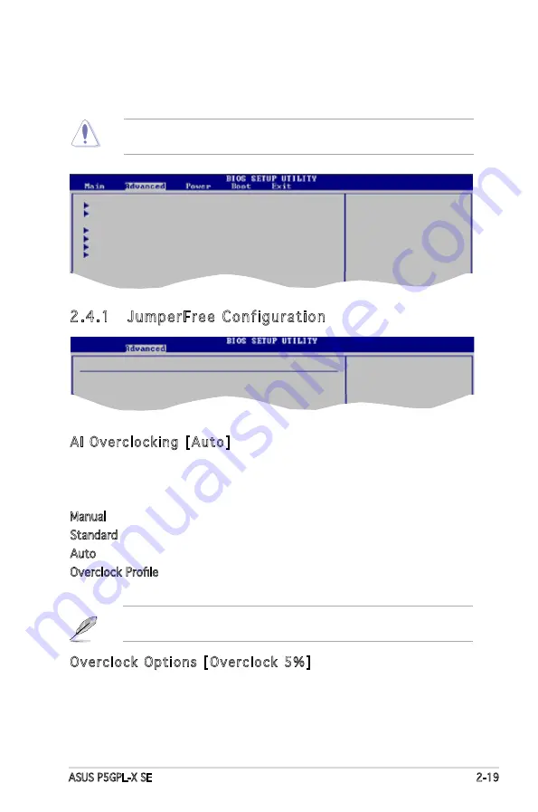
Advanced menu
The Advanced menu items allow you to change the settings for the CPU
and other system devices.
Take caution when changing the settings of the Advanced menu items.
Incorrect field values can cause the system to malfunction.
Configure CPU.
Select Screen
Select Item
Enter Go to Sub-screen
F1 General Help
F10 Save and Exit
ESC Exit
JumperFree Configuration
USB Configuration
CPU Configuration
Chipset
Onboard Devices Configuration
PCI PnP
2.4.1 JumperFree Configuration
AI Overclocking [Auto]
Allows selection of CPU overclocking options to achieve desired
CPU internal frequency. Select either one of the preset overclocking
configuration options:
Manual - allows you to individually set overclocking parameters.
Standard - loads the standard settings for the system.
Auto - loads the optimal settings for the system.
Overclock Profile - loads overclocking profiles with optimal parameters for
stability when overclocking.
Overclock Options [Overclock 5%]
Allows you to set the oveclocking options. Configuration options:
[Overclock 5%] [Overclock 10%] [Overclock 15%] [Overclock 20%]
[Overclock 30%] [FSB900/DDR1-450] [FSB1000/DDR1-500]
Configure System Frequency/Voltage
AI Overclocking
[Auto]
CPU Clock Free
[Auto]
The following items also appear when the AI Overclocking item is set to
[Overclock Profile].


