background image

ASUS P5BV-M

6-3

6.1.2.

Installing.the.RAID.controller.driver

Windows

®

.2000/2003.Server.OS

During.Windows

®

.2000/2003.Server.OS.installation

To install the RAID controller driver when installing Windows

®

 2000/2003 

Server OS:

1.  Boot the computer using the Windows

®

 2000/2003 Server installation CD. 

The 

Windows

®

.2000/2003.Setup

 starts.

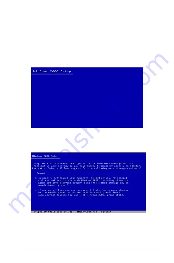
2.  Press <F6> when the message “

Press.F6.if.you.need.to.install.a.third.

party.SCSI.or.RAID.driver

...” appears at the bottom of the screen.

3.  When prompted, press 

<S>

 to specify an additional device.

Summary of Contents for P5B VM - AiLifestyle Series Motherboard

Page 1: ...Motherboard P5BV M ...

Page 2: ...RCHANTABILITY OR FITNESS FOR A PARTICULAR PURPOSE IN NO EVENT SHALL ASUS ITS DIRECTORS OFFICERS EMPLOYEES OR AGENTS BE LIABLE FOR ANY INDIRECT SPECIAL INCIDENTAL OR CONSEQUENTIAL DAMAGES INCLUDING DAMAGES FOR LOSS OF PROFITS LOSS OF BUSINESS LOSS OF USE OR DATA INTERRUPTION OF BUSINESS AND THE LIKE EVEN IF ASUS HAS BEEN ADVISED OF THE POSSIBILITY OF SUCH DAMAGES ARISING FROM ANY DEFECT OR ERROR IN...

Page 3: ...ormation 2 1 Before you proceed 2 1 2 2 Motherboard overview 2 2 2 2 1 Placement direction 2 2 2 2 2 Screw holes 2 2 2 2 3 Motherboard layout 2 3 2 2 4 Layout contents 2 4 2 3 Central Processing Unit CPU 2 5 2 3 1 Installing the CPU 2 5 2 3 2 Installing the CPU heatsink and fan 2 8 2 3 3 Uninstalling the CPU heatsink and fan 2 10 2 4 System memory 2 11 2 4 1 Overview 2 11 2 4 2 Memory configuratio...

Page 4: ...BIOS setup 4 1 Managing and updating your BIOS 4 1 4 1 1 Creating a bootable floppy disk 4 1 4 1 2 AFUDOS utility 4 2 4 1 3 ASUS CrashFree BIOS 3 utility 4 5 4 2 BIOS setup program 4 7 4 2 1 BIOS menu screen 4 8 4 2 2 Menu bar 4 8 4 2 3 Navigation keys 4 8 4 2 4 Menu items 4 9 4 2 5 Sub menu items 4 9 4 2 6 Configuration fields 4 9 4 2 7 Pop up window 4 9 4 2 8 Scroll bar 4 9 4 2 9 General help 4 ...

Page 5: ... 1 Boot Device Priority 4 27 4 6 2 Boot Settings Configuration 4 28 4 6 3 Security 4 29 4 7 Exit menu 4 32 Chapter 5 RAID configuration 5 1 Setting up RAID 5 1 5 1 1 RAID definitions 5 1 5 1 2 Installing hard disk drives 5 2 5 1 3 Setting the RAID item in BIOS 5 2 5 1 4 RAID configuration utility 5 2 5 2 LSI Logic Embedded SATA RAID Setup Utility 5 3 5 2 1 Creating a RAID 0 or RAID 1 set 5 4 5 2 2...

Page 6: ...the RAID 5 39 5 3 9 Setting the Boot array in the BIOS Setup Utility 5 40 5 4 Global Array Manager 5 41 Chapter 6 Driver installation 6 1 RAID driver installation 6 1 6 1 1 Creating a RAID driver disk 6 1 6 1 2 Installing the RAID controller driver 6 4 6 2 LAN driver installation 6 13 6 2 1 Windows 2000 2003 Server 6 13 6 3 VGA driver installation 6 15 6 3 1 Windows 2003 Server 6 15 6 4 Management...

Page 7: ...ause harmful interference to radio or television reception which can be determined by turning the equipment off and on the user is encouraged to try to correct the interference by one or more of the following measures Reorient or relocate the receiving antenna Increase the separation between the equipment and receiver Connect the equipment to an outlet on a circuit different from that to which the...

Page 8: ...f the power supply is broken do not try to fix it by yourself Contact a qualified service technician or your retailer Operation safety Before installing the motherboard and adding devices on it carefully read all the manuals that came with the package Before using the product make sure all cables are correctly connected and the power cables are not damaged If you detect any damage contact your dea...

Page 9: ...ttings through the BIOS Setup menus Detailed descriptions of the BIOS parameters are also provided Chapter 5 RAID configuration Provides information on RAID configurations for this motherboard Chapter 6 Driver installation This chapter provides information on RAID and LAN driver installation for this motherboard Appendix Reference information This appendix includes additional information that you ...

Page 10: ...ey Key1 Key2 Key3 If you must press two or more keys simultaneously the key names are linked with a plus sign Example Ctrl Alt Del Command Means that you must type the command exactly as shown then supply the required item or value enclosed in brackets Example At the DOS prompt type the command line format A S DANGER WARNING Information to prevent injury to yourself when trying to complete a task ...

Page 11: ...Maximum up to 8GB Memory Type DDR2 667 800 Unbuffered ECC Non ECC Memory Size 256MB 512 MB 1 GB 2GB Expansion Slots follow SSI Loacation Total PCI PCI X PCI E Slots 4 Slot Loacation 4 1 PCI 32bit 33 MHz Slot Loacation 5 1 PCI 32bit 33 MHz Slot Loacation 6 1 PCI E x8 x8 link PCIE2 slot Slot Loacation 7 1 PCI E x8 x4 link PCIE1 slot Additional Slot 1 1 SO DIMM socket for optional ASMB3 SOL ASMB3 iKV...

Page 12: ...ector 1 Auxiliary panel connector 1 Serial Port Header 1 Rear I O Connectors External Serial Port 1 External USB Port 2 VGA Port 1 RJ 45 2 RJ 45 for iKVM 1 PS 2 KB Mouse 1 Management Solution Software ASWM2 0 Out of Band Remote Management Optional ASMB3 SOL ASMB3 iKVM Monitoring CPU Temperature V FAN RPM V EMI US FCC CFR47 Part 15 Class B V Europe CE EN55022 EN55024 V Environment Operation tempera...

Page 13: ...1 Product introduction This chapter describes the motherboard features and the new technologies it supports ...

Page 14: ...ASUS P5BV M Chapter summary 1 1 1 Welcome 1 1 1 2 Package contents 1 1 1 3 Special features 1 2 ...

Page 15: ...Retail Pack P5BV M Bulk Pack Cables Serial ATA signal cable 4 Serial ATA power cable 2 2 in 1 Floppy Ultra ATA disk drive cable 1 SATA to SAS cable Accessories I O shield 1 10 Application CD Support CD 1 10 Documentation User guide 1 10 Packing Quantity Motherboard 3 pieces per Carton 10 pieces per Carton 1 3 Serial number label Before requesting support from the ASUS Technical Support team you mu...

Page 16: ...ng and system speed or power requirement Intel 3200 and Intel ICH7R chipset The Intel 3200 Memory Controller Hub MCH and the Intel ICH7R I O controller hub provide the vital interfaces for the motherboard The MCH provides the processor dual channel DDR2 667 800 memory and PCI Express interfaces The ICH7R is a new generation server class I O controller hub that provides the interface for PCI 2 3 US...

Page 17: ... pin count reduced voltage requirement and up to 300 MB s data transfer rate IR The LSI Logic Integrated RAID solution provides cost benefits for the server or workstation market where the extra performance storage capacity and or redundancy of a RAID configuration are required The two components of Integrated RAID are Integrated Mirroring IM which provides features of RAID 1 and RAID 1E RAID 1 En...

Page 18: ...ard compatible with USB 1 1 Temperature fan and voltage monitoring The CPU temperature is monitored by the ASIC integrated in the Winbond hardware monitor to prevent overheating and damage The system fan rotations per minute RPM is monitored for timely failure detection The ASIC monitors the voltage levels to ensure stable supply of current for critical components 1 4 2 Innovative ASUS features Cr...

Page 19: ... Hardware information This chapter lists the hardware setup procedures that you have to perform when installing system components It includes description of the jumpers and connectors on the motherboard ...

Page 20: ...5BV M Series Chapter summary 2 2 1 Before you proceed 2 1 2 2 Motherboard overview 2 2 2 3 Central Processing Unit CPU 2 8 2 4 System memory 2 15 2 5 Expansion slots 2 17 2 6 Jumpers 2 20 2 7 Connectors 2 24 ...

Page 21: ...e wall socket before touching any component Use a grounded wrist strap or touch a safely grounded object or a metal object such as the power supply case before handling components to avoid damaging them due to static electricity Hold components by the edges to avoid touching the ICs on them Whenever you uninstall any component place it on a grounded antistatic pad or in the bag that came with the ...

Page 22: ...e motherboard Failure to do so can cause you physical injury and damage to the motherboard components 2 2 1 Placement direction When installing the motherboard make sure that you place it into the chassis in the correct orientation The edge with external ports goes to the rear part of the chassis as indicated in the image below 2 2 2 Screw holes Place eight 8 screws into the holes indicated by cir...

Page 23: ... PCIE2 PCI4 Super I O FRNT_FAN1 CPU_FAN1 REAR_FAN1 CR2032 3V Lithium Cell CMOS Power AUX_PANEL1 FLOPPY1 SB_PWR1 RECOVERY1 P5BV M PS 2KBMS T Mouse B Keyboard LAN_USB12 LAN1 VGA1 COM1 LAN2 LGA775 CHAFAN_SET1 RAID_SEL1 HDLED1 TPM1 ATX12V1 EATXPWR1 CPUFAN_SET1 BUZZ1 PRI_IDE1 USB34 SATA3 SATA1 SATA2 SATA4 CLRTC1 PANEL1 ASMB3 COM2 8Mb BIOS BCM 5721 BCM 5721 Intel 3200 MCH Intel ICH7R ICH XGI Z9s Qimonda...

Page 24: ...ing 3 pin RECOVERY1 2 24 4 Fan mode setting 3 pin CPUFAN_SET1 and CHAFAN_SET1 2 25 Internal connectors Page 1 Floppy disk drive connector 34 1 pin FLOPPY1 2 27 2 ICH7R primary IDE connector 40 1 pin PRI_IDE1 2 28 3 Black Serial ATA connectors 7 pin SATA1 SATA2 SATA3 SATA4 2 29 4 USB connector 10 1 pin USB34 2 31 5 Serial port connector 10 1 pin COM2 2 31 6 CPU fan connector 4 pin CPU_FAN1 2 32 7 H...

Page 25: ... on the socket and the socket contacts are not bent Contact your retailer immediately if the PnP cap is missing or if you see any damage to the PnP cap socket contacts motherboard components ASUS shoulders the repair cost only if the damage is shipment transit related Keep the cap after installing the motherboard ASUS will process Return Merchandise Authorization RMA requests only if the motherboa...

Page 26: ...over the socket making sure that the gold triangle is on the bottom left corner of the socket The socket alignment key should fit into the CPU notch 2 Press the load lever with your thumb A then move it to the left B until it is released from the retention tab To prevent damage to the socket pins do not remove the PnP cap unless you are installing a CPU A B Load lever Retention tab Load plate PnP ...

Page 27: ...n only one correct orientation DO NOT force the CPU into the socket to prevent bending the connectors on the socket and damaging the CPU 6 Close the load plate A then push the load lever B until it snaps into the retention tab A B ...

Page 28: ...uy a boxed Intel Pentium 4 processor the package includes the CPU fan and heatsink assembly Your Intel Pentium 4 LGA775 heatsink and fan assembly comes in a push pin design and requires no tool to install If you purchased a separate CPU heatsink and fan assembly make sure that you have properly applied Thermal Interface Material to the CPU heatsink or CPU before you install the heatsink and fan as...

Page 29: ...et to connect the CPU fan connector Hardware monitoring errors can occur if you fail to plug this connector If there is only one CPU fan cable connect it to the connector labeled CPU FAN1 Failure to do so may cause hardware monitoring errors Set the CPU fan pin selection jumper to use a 3 pin or 4 pin fan cable plug Refer to 2 6 Jumpers for details A A B B 1 1 P5BV M CPU Fan Connector P5BV M GND F...

Page 30: ...otherboard 2 Rotate each fastener counterclockwise 3 Pull up two fasteners at a time in a diagonal sequence to disengage the heatsink and fan assembly from the motherboard B A A A B B B A 4 Carefully remove the heatsink and fan assembly from the motherboard Refer to the documentation in the boxed or stand alone CPU fan package for detailed information on CPU fan installation ...

Page 31: ... 2 Memory configurations You may install 256 MB 512 MB 1 GB and 2 GB unbuffered ECC or non ECC DDR2 667 800 DIMMs into the DIMM sockets Always install DIMMs with the same CAS latency For optimum compatibility we recommend that you obtain memory modules from the same vendor Refer to the DDR2 Qualified Vendors List on the ASUS web site When installing one or two DIMMs install the DIMM s to the blue ...

Page 32: ...1 1 2 4 3 4 DIMM socket DIMM_A1 V V V DIMM_A2 V V V V V DIMM_B1 V V DIMM_B2 V V V V V When the total size of memory module s installed per channel is the same A1 A2 B1 B2 the system will run in Dual Channel Interleaved mode which provides optimum performance When the total size of each channel is not the same A1 A2 B1 B2 the system will run in Dual Channel Asymmetric mode ...

Page 33: ...aining clips snap back in place and the DIMM is properly seated 2 4 4 Removing a DIMM Follow these steps to remove a DIMM 1 Simultaneously press the retaining clips outward to unlock the DIMM 2 Remove the DIMM from the socket A DDR2 DIMM is keyed with a notch so that it fits in only one direction DO NOT force a DIMM into a socket to avoid damaging the DIMM The DDR2 DIMM sockets do not support DDR ...

Page 34: ...re the card to the chassis with the screw you removed earlier 6 Replace the system cover 2 5 2 Configuring an expansion card After installing the expansion card configure it by adjusting the software settings 1 Turn on the system and change the necessary BIOS settings if any See Chapter 4 for information on BIOS setup 2 Assign an IRQ to the card Refer to the tables on the next page 3 Install the s...

Page 35: ... Bus Controller 16 Broadcom NetXtreme Gigabit Ethernet 16 PCI standard PCI to PCI bridge 16 PCI standard PCI to PCI bridge 16 PCI standard PCI to PCI bridge 17 Broadcom NetXtreme Gigabit Ethernet 2 17 PCI standard PCI to PCI bridge 18 Standard Universal PCI to USB Host Controller 19 Standard Universal PCI to USB Host Controller 19 Standard Dual Channel PCI IDE Contrller 23 Standard Enhanced PCI to...

Page 36: ...board LAN1 PIRQA Onboard LAN2 PIRQB Onboard VGA PIRQF PCI Bus Number IDSEL and IRQ assignments 2 5 5 PCI slots The PCI slots support cards such as a LAN card SCSI card USB card and other cards that comply with PCI 2 2 specifications The figure shows a LAN card installed on a 32 bit PCI slot 2 5 4 PCI Express x8 slot This motherboard supports PCI Express x8 network cards SCSI cards and other cards ...

Page 37: ...rn OFF the computer and unplug the power cord 2 Remove the onboard battery 3 Move the jumper cap from pins 1 2 default to pins 2 3 Keep the cap on pins 2 3 for about 5 10 seconds then move the cap back to pins 1 2 4 Re install the battery 5 Plug the power cord and turn ON the computer 6 Hold down the Del key during the boot process and enter BIOS setup to re enter data Except when clearing the RTC...

Page 38: ...overy setting 3 pin RECOVERY1 This jumper allows you to quickly update or recover the BIOS when it gets corrupted To update the BIOS 1 Prepare a floppy disk that contains the latest BIOS for the motherboard xxxx xxx ROM and the AFUDOS EXE utility 2 Set the jumper to pins 2 3 3 Insert the floppy disk then turn on the system to update the BIOS 4 Shut down the system 5 Set the jumper back to pins 1 2...

Page 39: ... 4 pin fan cable plug to the CPU fan or Chasis fan connectors Set these jumpers to pins 1 2 Short PWM mode if you are using a 4 pin fan cable plug or to pins 2 3 Short DC mode if you are using a 3 pin plug P5BV M Fan Mode Setting P5BV M 1 2 1 2 CPUFAN_SET1 Default PWM Mode DC Mode 2 3 CHAFAN_SET1 Default PWM Mode DC Mode 2 3 ...

Page 40: ... Lan port for ASMB3 IKVM 3 Dual integrated Gigabit Ethernet connections LAN1_LAN2 These ports allow Gigabit connection to a Local Area Network LAN through a network hub The left one is LAN1 the right one is LAN2 w i ASF function 4 VGA port This port is for a VGA monitor or other VGA compatible devices 5 Serial COM1 port This 9 pin communication port is for pointing devices or other serial devices ...

Page 41: ...rt one end of the cable to this connector then connect the other end to the signal connector at the back of the floppy disk drive Pin 5 on the connector is removed to prevent incorrect cable connection when using a FDD cable with a covered Pin 5 P5BV M Floppy Disk Drive Connector P5BV M NOTE Orient the red markings on the floppy ribbon cable to PIN 1 PIN1 FLOPPY1 ...

Page 42: ...tra DMA 100 66 IDE master device hard disk drive If you install two hard disk drives you must configure the second drive as a slave device by setting its jumper accordingly Refer to the hard disk documentation for the jumper settings Pin 20 on the IDE connector is removed to match the covered hole on the Ultra DMA cable connector This prevents incorrect insertion when you connect the IDE cable Use...

Page 43: ...IDE mode by default In IDE mode you can connect Serial ATA boot data hard disk drives to these connectors If you intend to create a Serial ATA RAID set using these connectors set the Configure SATA as item in the BIOS to RAID See section 4 3 5 IDE Configuration for details Important notes on Serial ATA Use only two Serial ATA RAID connectors for each RAID 0 or RAID 1 set P5BV M SATA Connectors P5B...

Page 44: ... that supports up to 480 Mbps connection speed The USB port module is purchased separately 5 Serial port connector 10 1 pin COM2 This connector is for a serial COM port Connect the serial port module cable to this connector then install the module to a slot opening at the back of the system chassis The Serial port module is purchased separately P5BV M USB 2 0 Connector P5BV M USB 5V USB_P4 USB_P4 ...

Page 45: ...or a total of 2 1 A 4 44 A 53 28 W max at 12V Connect the fan cables to the fan connectors on the motherboard making sure that the black wire of each cable matches the ground pin of the connector Do not forget to connect the fan cables to the fan connectors Insufficient air flow inside the system may damage the motherboard components These are not jumpers Do not place jumper caps on the fan connec...

Page 46: ...tem Do not forget to connect the 4 pin or 8 pin ATX 12 V power plug otherwise the system will not boot up We recommend that you use a PSU with a higher power output when configuring a system with more power consuming devices The system may become unstable or may not boot up if the power is inadequate You must install a PSU with a higher power rating if you intend to install additional devices P5BV...

Page 47: ...blinks when the system is in the boot process until the operating system is loaded 3 System warning speaker Orange 4 pin SPEAKER This 4 pin connector is for the chassis mounted system warning speaker The speaker allows you to hear system beeps and warnings 4 Hard disk drive activity LED Red 2 pin IDE_LED This 2 pin connector is for the HDD Activity LED Connect the HDD Activity LED cable to this co...

Page 48: ... the fan connectors on the motherboard making sure that the black wire of each cable matches the ground pin of the connector Do not forget to connect the fan cables to the fan connectors Insufficient air flow inside the system may damage the motherboard components These are not jumpers Do not place jumper caps on the fan connectors P5BV M Fan Connectors P5BV M GND FANPWR2 GND FANPWR2 FAN PWM CPU_F...

Page 49: ... LEDs on the front panel 3 Chassis Intrusion connector 3 pin CASEOPEN This lead is for a chassis with an intrusion detection feature This requires an external detection mechanism such as a chassis intrusion sensor or microswitch When you remove any chassis component the sensor triggers and sends a high level signal to this lead to record a chassis intrusion event 4 Locator LED 2 pin LOCATORLED1 an...

Page 50: ... is used to connect a Trusted Platform Module TPM Card You need to install ASUS TPM card to use this feature function The TPM module is purchased separately P5BV M TPM Connector P5BV M TPM 3 3V AD0 PWRDW AD1 AD2 SERIRQ CLKRUN NC GND PCICLK FRAME NC PCIRST AD3 GND 3 3VSB GND NC NC ...

Page 51: ...3 Powering up This chapter describes the power up sequence the vocal POST messages and ways of shutting down the system ...

Page 52: ...ASUS P5BV M Chapter summary 3 3 1 Starting up for the first time 3 1 3 2 Powering off the computer 3 2 ...

Page 53: ...ith green standards or if it has a power standby feature the monitor LED may light up or switch between orange and green after the system LED turns on The system then runs the Power On Self Test POST While the tests are running the BIOS beeps or additional messages appear on the screen If you do not see anything within 30 seconds from the time you turned on the power the system may have failed a p...

Page 54: ...dows Server 2003 1 Click the Start button then select Turn Off Computer 2 Click the Turn Off button to shut down the computer 3 The power supply should turn off after Windows shuts down 3 2 2 Using the dual function power switch While the system is ON pressing the power switch for less than four seconds puts the system to sleep mode or to soft off mode depending on the BIOS setting Pressing the po...

Page 55: ...4 BIOS setup This chapter tells how to change the system settings through the BIOS Setup menus Detailed descriptions of the BIOS parameters are also provided ...

Page 56: ...apter summary 4 ASUS P5BV M 4 1 Managing and updating your BIOS 4 1 4 2 BIOS setup program 4 10 4 3 Main menu 4 13 4 4 Advanced menu 4 18 4 5 Power Configuration 4 27 4 6 Boot menu 4 31 4 7 Exit menu 4 36 ...

Page 57: ...of the following to create a bootable floppy disk DOS environment a Insert a 1 44MB floppy disk into the drive b At the DOS prompt type format A S then press Enter Windows 2000 environment To create a set of boot disks for Windows 2000 a Insert a formatted high density 1 44 MB floppy disk into the drive b Insert the Windows 2000 CD to the optical drive c Click Start then select Run d From the Open...

Page 58: ... 07 03 11 24BB Copyright C 2002 American Megatrends Inc All rights reserved Reading flash done Write to file ok A 1 Copy the AFUDOS utility afudos exe from the motherboard support CD to the bootable floppy disk you created earlier 2 Boot the system in DOS mode then at the prompt type afudos o filename where the filename is any user assigned filename not more than eight alphanumeric characters for ...

Page 59: ... for the motherboard Save the BIOS file to a bootable floppy disk A afudos iP5BVM ROM Write the BIOS filename on a piece of paper You need to type the exact BIOS filename at the DOS prompt A afudos iP5BVM ROM AMI Firmware Update Utility Version 1 19 ASUS V2 07 03 11 24BB Copyright C 2002 American Megatrends Inc All rights reserved WARNING Do not turn off power during flash BIOS Reading file done R...

Page 60: ...AT16 or 32 system file before updating the BIOS To format the USB flash drive to a FAT32 16 system file 1 Insert the USB flash drive to an available USB port 2 From the Windows desktop click Start then select My computer 3 Right click the USB flash drive icon then select Format from the menu 4 From the File system field select FAT32 or FAT16 then click the Start button To update the BIOS file 1 Co...

Page 61: ...isk that contains BIOS file to the USB port 2 Turn on the system 3 The utility will automatically checks the devices for the BIOS file when found the utility reads the BIOS file and starts flashing the corrupted BIOS file 4 Restart the system after the utility completes the updating process Only the USB flash disk with FAT 32 16 format and single partition can support ASUS CrashFree BIOS 3 The dev...

Page 62: ...S checksum Starting BIOS recovery Checking for floppy Floppy found Reading file P5BVM ROM Completed Start flashing When found the utility reads the BIOS file and starts flashing the corrupted BIOS file DO NOT shut down or reset the system while updating the BIOS Doing so can cause system boot failure ...

Page 63: ...s Delete during the Power On Self Test POST to enter the Setup utility otherwise POST continues with its test routines If you wish to enter Setup after POST restart the system by pressing Ctrl Alt Delete or by pressing the reset button on the system chassis You can also restart by turning the system off and then back on Do this last option only if the first two failed The Setup program is designed...

Page 64: ...s for that particular menu Use the navigation keys to select items in the menu and change the settings 4 2 1 BIOS menu screen Some of the navigation keys differ from one screen to another Navigation keys Sub menu items General help Menu bar Configuration fields Menu items Select Screen Select Item Change Option F1 General Help F10 Save and Exit ESC Exit v02 58 C Copyright 1985 2004 American Megatr...

Page 65: ...Down arrow keys or Page Up Page Down keys to display the other items on the screen 4 2 9 General help At the top right corner of the menu screen is a brief description of the selected item Main menu items System Time 11 10 19 System Date Tue 01 01 2002 Legacy Diskette A 1 44M 3 5 in Primary IDE Master Not Detected Primary IDE Slave Not Detected Third IDE Master Not Detected Third IDE Slave Not Det...

Page 66: ...n 2 88M 3 5 in Refer to section 4 2 1 BIOS menu screen for information on the menu screen items and how to navigate through them v02 58 C Copyright 1985 2004 American Megatrends Inc System Time 11 10 19 System Date Tue 01 08 2002 Legacy Diskette A 1 44M 3 5 in Primary IDE Master Not Detected Primary IDE Slave Not Detected SATA 1 Not Detected SATA 2 Not Detected SATA 3 Not Detected SATA 4 Not Detec...

Page 67: ...se values are not user configurable These items show N A if no IDE device is installed in the system Type Auto Selects the type of IDE drive Setting to Auto allows automatic selection of the appropriate IDE device type Select CDROM if you are specifically configuring a CD ROM drive Select ARMD ATAPI Removable Media Device if your device is either a ZIP LS 120 or MO drive Configuration options Not ...

Page 68: ...abled Compatible Enhanced Configure SATA as IDE Set the SATA configuration Configuration options IDE RAID AHCI 4 3 5 IDE Configuration The items in this menu allow you to set or change the configurations for the IDE devices installed in the system Select an item then press Enter if you wish to configure the item IDE Configuration ATA IDE Configuration Enhanced Configure SATA as IDE Hard Disk Write...

Page 69: ...on F1 General Help F10 Save and Exit ESC Exit BIOS SETUP UTILITY Main v02 58 C Copyright 1985 2007 American Megatrends Inc Hard Disk Write Protect Disabled Enables or disables the device write protection This will be effective only if device is accessed through BIOS Configuration options Disabled Enabled IDE Detect Time Out Sec 35 Selects the time out value for detecting ATA ATAPI devices Configur...

Page 70: ...Enabled None USB Functions Enabled USB2 0 Controller Enabled Legacy USB Support Auto USB2 0 Controller Mode HiSpeed BIOS EHCI Hand Off Enabled 4 4 1 USB Configuration USB Function Enabled Allows you to enable a specific number of USB ports or disable the USB function Configuration options Disabled Enabled USB Configuration Remote Access Configuration Trusted Computing MPS Configuration CPU Configu...

Page 71: ...ce connected Configuration options Disabled Enabled Auto USB 2 0 Controller Enabled Allows you to enable or disable the USB 2 0 controller Configuration options Enabled Disabled USB2 0 Controller mode HiSpeed Allows you to select the USB2 0 controller mode Configuration options HiSpeed FullSpeed BIOS EHCI Hand Off Enabled Allows yout to enable or disable the BIOS EHCI Hand Off support function Con...

Page 72: ...select a serial port for console redirection Configuration options COM1 COM2 Serial Port Mode 115200 8 n 1 Allows you to select a serial port mode Configuration options 115200 8 n 1 57600 8 n 1 38400 8 n 1 19200 8 n 1 09600 8 n 1 Flow Control None Allows you to set the flow control for console redirection Configuration options None Hardware Software Redirection After BIOS POST Always Sets the redi...

Page 73: ...tions No Yes Select Screen Select Item Change Option F1 General Help F10 Save and Exit ESC Exit Enable Disable TPM TCG TPM 1 1 1 2 supp in BIOS Trusted Computing TCG TPM SUPPORT No BIOS SETUP UTILITY Advanced 4 4 3 Trusted Computing v02 58 C Copyright 1985 2007 American Megatrends Inc Select Screen Select Item Change Option F1 General Help F10 Save and Exit ESC Exit BIOS SETUP UTILITY Advanced Sel...

Page 74: ... feature flag to always return to 0 Configuration options Disabled Enabled PECI Disabled Allows you to enable or disable the PECI Configuration options Enabled Disabled Select Screen Select Item Change Option F1 General Help F10 Save and Exit ESC Exit Configure advanced CPU settings Module Version 3D 06 Manufacturer Intel Brand String Intel R Core TM 2 CPU 6300 1 86GHz Frequency 1 86GHz FSB Speed ...

Page 75: ...u to enable or disable Intel SpeedStep technology Configuration options Disabled Enabled Advanced Chipset Settings WARNING Setting wrong values in below sections may cause system to malfunction North Bridge Configuration South Bridge Configuration Configure North Bridge features North Bridge chipset Configuration Memory Remap Feature Enabled PCI MMIO Allocation 4GB To 3584MB DRAM Frequency Auto Co...

Page 76: ... manually set the DRAM timing parameters through the DRAM sub items Configuration options Enabled Disabled Initiate Graphic Adapter PEG PCI Allows you to select the graphics controller as the primary boot device Configuration options PCI PEG PEG PCI PEG Port Configuration PEG Port Auto Configuration options Auto Disabled South Bridge chipset Configuration SMBUS Controller Enabled SLP_S4 Min Assert...

Page 77: ... Base Addresses Serial Port1 Address 3F8 IRQ4 Allows you to select the Serial Port1 base address Configuration options Disabled 3F8 IRQ4 3E8 IRQ4 Serial Port2 Address 2F8 IRQ3 Allows you to select the Serial Port2 base address Configuration options Disabled 2F8 IRQ3 2E8 IRQ3 Serial Port2 Mode Normal Allows you to select the Serial Port2 mode Configuration options Normal IrDA ASK IR PCIE LAN 5721A ...

Page 78: ... latency timer register Configuration options 32 64 96 128 160 192 224 248 Allocate IRQ to PCI VGA Yes When set to Yes BIOS assigns an IRQ to PCI VGA card if the card requests for an IRQ When set to No BIOS does not assign an IRQ to the PCI VGA card even if requested Configuration options No Yes Advanced PCI PnP Settings WARNING Setting wrong values in below sections may cause system to malfunctio...

Page 79: ... the RSDT pointer list Configuration options Disabled Enabled ACPI 2 0 Support Disabled ACPI APIC Support Enabled APM Configuration Hardware Monitor Select Screen Select Item Change Option F1 General Help F10 Save and Exit ESC Exit Add additional tables as per ACPI 2 0 specifications BIOS SETUP UTILITY Main Advanced Power Boot Exit Palette Snooping Disabled When set to Enabled the pallete snooping...

Page 80: ...oes on after an AC power loss When set to Last State the system goes into either off or on state whatever the system state was before the AC power loss Configuration options Power Off Power On Last State Resume On Ring Disabled When set to Enabled the system enables the RI to generate a wake event while the computer is in Soft off mode Configuration options Disabled Enabled Resume On PME Disabled ...

Page 81: ...ay the detected temperatures CPU_Fan1 Speed xxxxRPM or N A FRNT_Fan1 Speed xxxxRPM or N A Rear_Fan1 Speed xxxxRPM or N A The onboard hardware monitor automatically detects and displays the CPU front and rear fan speed in rotations per minute RPM If the fan is not connected to the motherboard the field shows N A The following items appear only when the Resume On RTC Alarm item is set to Enabled RTC...

Page 82: ...the CPU Smart Fan Control item to Enabled CPU Fan Ratio XXX CPU Target Temperature XXX Displays the detected CPU and system threshold temperature when the Smart Fan Control is enabled FRNT_Fan1 Speed N A Rear_Fan1 Speed N A Allows you to enable or disable the front and rear fans Configuration options Ignored N A VCORE Voltage 3 3V Voltage 5V Voltage 12V Voltage VBAT Voltage and 3VSB Voltage The on...

Page 83: ...ings Configuration Security Select Screen Select Item Change Option F1 General Help F10 Save and Exit ESC Exit Specifies the Boot Device Priority sequence A virtual floppy disk drive Floppy Drive B may appear when you set the CD ROM drive as the first boot device BIOS SETUP UTILITY Main Advanced Power Boot Exit v02 58 C Copyright 1985 2007 American Megatrends Inc Boot Device Priority 1st Boot Devi...

Page 84: ...Logo2 feature AddOn ROM Display Mode Force BIOS Allows you to set display mode for optional ROM Configuration options Force BIOS Keep Current Bootup Num Lock On Allows you to select the power on state for the NumLock Configuration options Off On PS 2 Mouse Support Auto Allows you to enable or disable support for PS 2 mouse Configuration options Disabled Enabled Auto v02 58 C Copyright 1985 2007 Am...

Page 85: ...visor Password Select this item to set or change the supervisor password The Supervisor Password item on top of the screen shows the default Not Installed After you set a password this item shows Installed To set a Supervisor Password 1 Select the Change Supervisor Password item then press Enter 2 From the password box type a password composed of at least six letters and or numbers then press Ente...

Page 86: ...rvisor Password Installed User Password Not Installed Change Supervisor Password User Access Level Full Access Change User Password Clear User Password Password Check Setup User Access Level Full Access This item allows you to select the access restriction to the Setup items Configuration options No Access View Only Limited Full Access No Access prevents user access to the Setup utility View Only ...

Page 87: ...r you set your password successfully To change the user password follow the same steps as in setting a user password Clear User Password Select this item to clear the user password Password Check Setup When set to Setup BIOS checks for user password when accessing the Setup utility When set to Always BIOS checks for user password both when accessing Setup and booting the system Configuration optio...

Page 88: ...ou wish to cancel the command select Cancel then press Enter to return to the Exit menu Exit Discard Changes Select this option then press Enter to exit the Setup utility without saving your changes When a confirmation window appears select OK then press Enter to discard your changes and exit Setup If you wish to cancel the command select Cancel then press Enter to return to the Exit menu Discard ...

Page 89: ...command select Cancel then press Enter to return to the Exit menu Load Setup Defaults Select this option then press Enter to load the optimized settings for each of the Setup menu items When a confirmation window appears select OK then press Enter to load the default settings If you wish to cancel the command select Cancel then press Enter to return to the Exit menu ...

Page 90: ...5 RAID configuration This chapter provides instructions for setting up creating and configuring RAID sets using the available utilities ...

Page 91: ...ASUS P5BV M Chapter summary 5 5 1 Setting up RAID 5 1 5 2 LSI Logic Embedded SATA RAID Setup Utility 5 3 5 3 Intel Matrix Storage Manager Option ROM Utility 5 26 5 4 Global Array Manager 5 41 ...

Page 92: ...ins a complete copy of the data in the other drive This RAID configuration provides data protection and increases fault tolerance to the entire system Use two new drives or use an existing drive and a new drive for this setup The new drive must be of the same size or larger than the existing drive RAID 1 E Enhanced RAID 1 has a striped layout with each stripe unit having a secondary or alternate c...

Page 93: ...he Intel ICH7R Southbridge chip To do this 1 Enter the BIOS Setup during POST 2 Go to the Main Menu select IDE Configuration then press Enter 3 Set the ATA IDE Configuration item to Enhanced Mode then press Enter 4 Set the Configure SATA as item to RAID 5 Save your changes then exit the BIOS Setup Refer to Chapter 4 for details on entering and navigating through the BIOS Setup 5 1 4 RAID configura...

Page 94: ... create RAID 0 RAID1 orRAID10 set s fromSATAharddiskdrivesconnectedtotheSATAconnectors supported by the motherboard Southbridge chip To enter the LSI Logic Embedded SATA RAID Setup Utility 1 Turn on the system after installing all the SATA hard disk drives 2 During POST the LSI Logic Embedded SATA RAID Setup Utility automatically detects the installed SATA hard disk drives and displays any existin...

Page 95: ...g the Easy Configuration option 1 From the utility main menu highlight Configure then press Enter 2 Use the arrow keys to select Easy Configuration then press Enter Menu Description Configure Allows you to create RAID 0 or RAID 1 set using the Easy Configuration or the New Configuration command This menu also allows you to view add or clear RAID configurations or select the boot drive Initialize A...

Page 96: ... MENU displays the available drives connected to the SATA ports Select the drives you want to include in the RAID set then press SpaceBar When selected the drive indicator changes from READY to ONLIN A X Y where X is the array number and Y is the drive number The information of the selected hard disk drive displays at the bottom of the screen ...

Page 97: ...D configuration 5 Press F10 select the configurable array then press SpaceBar Press F10 again the logical drive information appears including a Logical Drive menu that allows you to change the logical drive parameters ...

Page 98: ... at least two identical hard disk drives when creating a RAID 1 set 8 When creating a RAID 1 set select DWC from the Logical Drive menu then press Enter When creating a RAID 0 set proceed to step 10 9 Select On to enable the Disk Write Cache setting then press Enter Enabling DWC can improve the performance but with the risk of data loss ...

Page 99: ...ct Accept from the menu then press Enter 11 When finished setting the selected logical drive configuration select Accept from the menu then press Enter 12 Follow steps 5 to 10 to configure additional logical drives 13 When prompted save the configuration then press Esc to return to the Management Menu ...

Page 100: ...r create another RAID configuration To create a RAID set using the New Configuration option 1 From the utility main menu highlight Configure then press Enter 2 Use the arrow keys to select New Configuration then press Enter 3 Follow steps 3 to 7 of the previous section 4 Select Size from the Logical Drive menu then press Enter 5 Key in the desired logical drive size then press Enter 6 Follow steps...

Page 101: ...press Enter 2 Use the arrow keys to select Easy Configuration then press Enter 3 The ARRAY SELECTION MENU displays the available drives connected to the SATA ports Select the drive s you want to include in the RAID set then press SpaceBar When selected the drive indicator changes from READY to ONLIN A X Y where X is the array number and Y is the drive number The information of the selected hard di...

Page 102: ...ASUS P5BV M 5 11 4 Select all the drives required for the RAID 10 set then press Enter The configurable array appears on screen 5 Press F10 select the configurable array then press SpaceBar ...

Page 103: ...nge the logical drive parameters 6 Select RAID from the Logical Drive menu then press Enter 7 Select RAID 10 from the menu then press Enter You need at least four identical hard disk drives when creating a RAID 10 set 8 Select DWC from the Logical Drive menu then press Enter 9 Select On to enable the Disk Write Cache setting then press Enter ...

Page 104: ...BV M 5 13 10 When finished setting the selected logical drive configuration select Accept from the menu then press Enter 11 When prompted save the configuration then press Esc to return to the Management Menu ...

Page 105: ...Menu highlight Configure then press Enter 2 Use the arrow keys to select View Add Configuration then press Enter 3 The ARRAY SELECTION MENU displays the available drives connected to the SATA ports Select the drive s you want to include in the RAID set then press SpaceBar When selected the drive indicator changes from READY to ONLIN A X Y where X is the array number and Y is the drive number The i...

Page 106: ...AID set then press Enter The configurable array appears on screen 5 Press F10 select the configurable array then press SpaceBar 6 Press F10 again and select RAID from the Logical Drive menu then press Enter 7 Select the RAID level from the menu then press Enter ...

Page 107: ...the Creating a RAID set Using Easy Configuration section 9 When prompted save the configuration then press Esc to return to the Management Menu 10 Follow steps 8 to 13 of the Creating a RAID set Using Easy Configuration section to add the new RAID configuration ...

Page 108: ... or Objects command on the Management Menu Using the Initialize command To initialize the logical drive using the Initialize command 1 From the Management Menu highlight Initialize then press Enter 2 The screen displays the available RAID set s and prompts you to select the logical drive to initialize Use the arrow keys to select the logical drive from the Logical Drive selection then press Enter ...

Page 109: ... to select Yes from the Initialize dialog box then press Enter You may also press F10 to initialize the drive without confirmation Initializing a logical drive s erases all data on the drive 4 A progress bar appears on screen If desired press Esc to abort initialization ...

Page 110: ...S P5BV M 5 19 5 When initialization is completed press Esc Using the Objects command To initialize the logical drives using the Objects command 1 From the Management Menu highlight Objects then press Enter ...

Page 111: ... Select Logical Drive from the Objects sub menu then press Enter 3 Select the logical drive to initialize from the Logical Drives sub menu then press Enter 4 Select Initialize from the pop up menu then press Enter to start initialization ...

Page 112: ... When prompted press the SpaceBar to select Yes from the Initialize dialog box then press Enter 6 A progress bar appears on screen If desired press Esc to abort initialization 7 When initialization is completed press Esc ...

Page 113: ...k drives using the Rebuild command in the Management Menu To rebuild a failed hard disk drive 1 From the Management Menu highlight Rebuild then press Enter 2 The PHYSICAL DRIVES SELECTION MENU displays the available drives connected to the SATA ports Select the drive you want to rebuild then press SpaceBar ...

Page 114: ...V M 5 23 3 After selecting the drive to rebuild press F10 The indicator for the selected drive now shows RBLD 4 When prompted press Y to to rebuild the drive 5 When rebuild is complete press any key to continue ...

Page 115: ...lected option in the Objects Adapter menu The Check Consistency command is available only for logical drives included in a RAID 1 set Using the Check Consistency To check data consistency using the Check Consistency command 1 From the Management Menu select Check Consistency then press Enter 2 The screen displays the available RAID set s and prompts you to select the logical drive to check Press t...

Page 116: ...isk consistency press Esc to display the following options Stop Stops the consistency check The utility stores the percentage of disk checked When you restart checking it continues from the last percentage completed rather than from zero percent Continue Continues the consistency check Abort Aborts the consistency check When you restart checking it continues from zero percent 5 When checking is co...

Page 117: ...lect Objects then select Logical Drive from the menu 2 Use the arrow keys to select the logical drive you want to check then press Enter 3 Select Check Consistency from the pop up menu then press Enter 4 When prompted use the arrow keys to select Yes from the dialog box to check the drive 5 When checking is complete press any key to continue ...

Page 118: ...ID configuration 1 From the Management Menu select Configure Clear Configuration then press Enter 2 When prompted use the arrow keys to select Yes from the Clear Configuration dialog box then press Enter The utility clears the current array 3 Press any key to continue ...

Page 119: ...D set Refer to the Creating a RAID set Using New Configuration section for details To select the boot drive from a RAID set 1 From the Management Menu select Configure Select Boot Drive then press Enter 2 When prompted use the arrow keys to select the bootable logical drive from the list then press Enter 3 The logical drive is selected as boot drive Press any key to continue ...

Page 120: ...u enable WriteCache you may lose data when a power interruption occurs while transmitting or exchanging data among the drives To enable WriteCache 1 From the Management Menu select Objects Adapter then press Enter to display the adapter properties 2 Select WriteCache then press Enter to turn the option On enabled 3 When finished press any key to continue ...

Page 121: ... Option ROM v5 0 0 1032 ICH7R wRAID5 Copyright C 2003 05 Intel Corporation All Rights Reserved MAIN MENU 1 Create RAID Volume 2 Delete RAID Volume 3 Reset Disks to Non RAID 4 Exit DISK VOLUME INFORMATION RAID Volumes None defined Physical Disks Port Drive Model Serial Size Type Status Vol ID 0 XXXXXXXXXXX XXXXXXXX XX XXGB Non RAID Disk 1 XXXXXXXXXXX XXXXXXXX XX XXGB Non RAID Disk 2 XXXXXXXXXXX XXX...

Page 122: ...ORMATION Enter a string between 1 and 16 characters in length that can be used to uniquely identify the RAID volume This name is case sensitive and cannot contain special characters Change TAB Next ESC Previous Menu Enter Select Name RAID Level Disks Strip Size Capacity Volume0 RAID0 Stripe Select Disks 128KB 0 0 GB Create Volume SELECT DISKS Previous Next SPACE Selects ENTER Selection Complete Po...

Page 123: ...o create this volume Y N 9 Press Y to create the RAID volume and return to the main menu or N to go back to the Create Volume menu TIP We recommend a lower stripe size for server systems and a higher stripe size for multimedia computer systems used mainly for audio and video editing 7 Key in the RAID volume capacity that you want then press Enter The default value indicates the maximum allowed cap...

Page 124: ... RAID volume capacity that you want then press Enter The default value indicates the maximum allowed capacity 7 Press Enter when the Create Volume item is highlighted This warning message appears Intel R Matrix Storage Manager Option ROM v5 0 0 1032 ICH7R wRAID5 Copyright C 2003 05 Intel Corporation All Rights Reserved CREATE ARRAY MENU DISK VOLUME INFORMATION Enter a string between 1 and 16 chara...

Page 125: ...size for the RAID 10 array then press Enter The available stripe size values range from 8 KB to 128 KB The default stripe size is 64 KB Intel R Matrix Storage Manager Option ROM v5 0 0 1032 ICH7R wRAID5 Copyright C 2003 05 Intel Corporation All Rights Reserved CREATE ARRAY MENU DISK VOLUME INFORMATION Enter a string between 1 and 16 characters in length that can be used to uniquely identify the RA...

Page 126: ...3 05 Intel Corporation All Rights Reserved CREATE ARRAY MENU DISK VOLUME INFORMATION Enter a string between 1 and 16 characters in length that can be used to uniquely identify the RAID volume This name is case sensitive and cannot contain special characters Name RAID Level Disks Strip Size Capacity Volume5 RAID5 Parity Select Disks 64KB 0 0 GB Create Volume Change TAB Next ESC Previous Menu Enter ...

Page 127: ... completing your selection 6 When the Stripe Size item is highlighted press the up down arrow key to select the stripe size for the RAID 5 array then press Enter The available stripe size values range from 8 KB to 128 KB The default stripe size is 64 KB WARNING ALL DATA ON SELECTED DISKS WILL BE LOST Are you sure you want to create this volume Y N 9 Press Y to create the RAID volume and return to ...

Page 128: ...d cause any member disks to become available as non RAID disks WARNING EXISTING DATA WITHIN THIS VOLUME WILL BE LOST AND NON RECOVERABLE Select ESC Previous Menu Del Delete Volume 3 Press Y to delete the RAID set and return to the utility main menu otherwise press N to return to the Delete Volume menu ALL DATA IN THE VOLUME WILL BE LOST Are you sure you want to delete volume VolumeX Y N DELETE VOL...

Page 129: ...Follow steps 2 to 4 to select and reset other RAID set drives RESET RAID DATA Resetting RAID data will remove internal RAID structures from the selected RAID disks By removing these structures the drive will revert back to a non RAID disk WARNING Resetting a disk causes all data on the disk to be lost Port Drive Model Serial Size Status 0 XXXXXXXXXXXX XXXXXXXX XX XGB Member Disk 1 XXXXXXXXXXXX XXX...

Page 130: ...re is a non RAID SATAHard Disk available the utility will prompt to rebuild the RAID Press Enter then use up down arrow keys to select the destination disk or press ESC to exit Select a destination disk with the same size as the original hard disk 3 The utilty immediately starts rebuilding after the disk is selected The status of the degraded RAID volume is changed to Rebuild DEGRADED VOLUME DETEC...

Page 131: ...the RAID with a new hard disk 1 Remove the failed SATAhard disk and install a new SATAhard disk of the same specification into the same SATA Port 5 3 9 Setting the Boot array in the BIOS Setup Utility You can set the boot priority sequence in the BIOS for your RAID arrays when creating multi RAID using the Intel Matrix Storage Manager To set the boot array in the BIOS 2 Reboot the system and then ...

Page 132: ...u may also create a RAID set s in Windows operating environment using the Global Array Manager GAM application The GAM application is available from the motherboard support CD Refer to the GAM user guide in the motherboard support CD for details ...

Page 133: ...6 Driver installation This chapter provides instructions for installing the necessary drivers for different system components ...

Page 134: ...ASUS P5BV M Chapter summary 6 6 1 RAID driver installation 6 1 6 2 LAN driver installation 6 11 6 3 VGA driver installation 6 13 6 4 Management applications and utilities installation 6 15 ...

Page 135: ...d Hat Enterprise ver 3 0 SuSE operating system on a hard disk drive that is included in a RAID set You can create a RAID driver disk in DOS using the Makedisk application in the support CD To create a RAID driver disk in DOS environment 1 Place the motherboard support CD in the optical drive 2 Restart the computer then enter the BIOS Setup 3 Select the optical drive as the first boot priority to b...

Page 136: ...CH7R INTEL RAID Driver ICH7R LSI RAID Driver Broadcom ASF Firmware Update 7 Locate the RAID driver and place a blank high density floppy disk to the folppy disk drive 8 Press Enter 9 Follow screen instructions to create the driver disk ...

Page 137: ... controller driver when installing Windows 2000 2003 Server OS 1 Boot the computer using the Windows 2000 2003 Server installation CD The Windows 2000 2003 Setup starts 2 Press F6 when the message Press F6 if you need to install a third party SCSI or RAID driver appears at the bottom of the screen 3 When prompted press S to specify an additional device ...

Page 138: ...en press Enter 5 Select the RAID controller driver from the list then press Enter LSI Logic SATA RAID Select LSI Logic Embedded SATA RAID for Windows 2000 or 32bit Windows 2003 Server OS from the list then press Enter For 64bit Windows 2003 Server OS please select LSI Logic Embedded SATA RAID Intel IA32E item ...

Page 139: ...the Intel SATA AHCI Driver during windows setup Then select the Intel R 82801GR GH SATA AHCI Controller Desktop ICH7RDH from the list Refer to section 6 1 1 Creating a RAID driver disk to create the Intel SATA Driver for windows system 6 The Windows 2000 2003 Setup loads the RAID controller drivers from the RAID driver disk When prompted press Enter to continue installation 7 Setup then proceeds w...

Page 140: ...oller drivers When found click Next to install the drivers 11 Click Finish after the driver installation is done To an existing Windows 2000 2003 Server OS To install the RAID controller driver on an existing Windows 2000 2003 Server OS 1 Restart the computer then log in with Administrator privileges 2 Windows automatically detects the RAID controller and displays a New Hardware Found window Click...

Page 141: ...then click the Device Manager button 3 Click the sign before the item SCSI and RAID controllers The LSI Logic Embedded SATA RAID or Intel 8201 GR GH SATA RAID items should appear 4 Right click the RAID controller driver item then select Properties from the menu 5 Click the Driver tab then click the Driver Details button to display the RAID controller drivers 6 Click OK when finished ...

Page 142: ... Hat Enterprise To install the Intel ICH7R LSI Logic Embedded SATA RAID controller driver when installing Red Hat Enterprise operating system 1 Boot the system from the Red Hat Installation CD 2 At the boot type linux dd then press Enter ...

Page 143: ...M 6 4 Select fd0 using the Tab key when asked to select the driver disk source Press Tab to move the cursor to OK then press Enter 3 Select Yes using the Tab key when asked if you have the driver disk Press Enter ...

Page 144: ...select Yes then install the additional RAID controller drivers 7 Follow screen instructions to continue the OS installation 5 When prompted insert the Red Hat Enterprise RAID driver disk to the floppy disk drive select OK then press Enter The drivers for the RAID controller are installed to the system ...

Page 145: ... from the SuSE Installation CD 2 Select Installation from the Boot Options menu then press Enter 3 A message instructs you to prepare the RAID driver disk Press F6 For SuSE Linux Enterprise Server 9 0 SP1 operating system do not use OS bundled driver otherwise your computer may become unstable due to OS limitation ...

Page 146: ...rompted insert the RAID driver disk to the floppy disk drive then press Enter 5 When prompted select the floppy disk drive fd0 as the driver update medium select OK then press Enter The drivers for the RAID controller are installed to the system ...

Page 147: ... optical drive The CD automatically displays the Drivers menu if Autorun is enabled in your computer Windows automatically detects the LAN controllers and displays a New Hardware Found window Click Cancel to close this window If Autorun is NOT enabled in your computer browse the contents of the support CD to locate the file ASSETUP EXE from the BIN folder Double click the ASSETUP EXE to run the CD...

Page 148: ...ment tools before building the driver from the TAR file To build the driver from the TAR file 1 Create a directory and extract the TAR files tar xvzf bcm5700 version tar gz 2 Build the driver bcm5700 o as a loadable module for the running kernel cd bcm5700 version src make 3 Test the driver by loading it insmod bcm5700 o 4 Install the driver and man page make install 5 Refer to Red Hat distributio...

Page 149: ...the computer then log on with Administrator privileges 2 Insert the motherboard system support CD to the optical drive The support CD automatically displays the Drivers menu if Autorun is enabled in your computer Windows automatically detects the VGA controller and displays a New Hardware Found window Click Cancel to close this window 3 Click the item XGI VOLARI Z9s from the Drivers menu 4 The XGI...

Page 150: ...rivers menu if Autorun is enabled in your computer If Autorun is NOT enabled in your computer browse the contents of the support CD to locate the file ASSETUP EXE from the BIN folder Double click the ASSETUP EXE to run the CD 6 4 2 Drivers menu The Drivers menu shows the available device drivers if the system detects installed devices Install the necessary drivers to activate the devices The scree...

Page 151: ...ement Software menu displays the available network and server monitoring application Click on an item to install 6 4 4 Utilities menu The Utilities menu displays the software applications and utilities that the motherboard supports Click on an item to install ...

Page 152: ...6 18 Chapter 6 Driver installation 6 4 5 Contact information Click the Contact tab to display the ASUS contact information You can also find this information on the inside front cover of this user guide ...

Page 153: ...A Reference information This appendix includes additional information that you may refer to when configuring the motherboard ...

Page 154: ...ASUS P5BV M Chapter summary A A 1 P5BV M block diagram A 1 ...

Page 155: ...ASUS P5BV M A A 1 P5BV M block diagram ...

Page 156: ...A Appendix A Reference information ...

Reviews: