background image

GTC 

  Service Manual


72 


R1913 

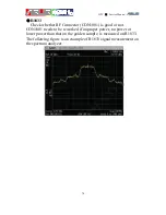
Check whether Coupler (U1907) is good or not. U1907 needs to be 

reworked if improper power, no power or lower power than that on 
the golden sample, is measured on R1913. The following figure is an 
example of R1913 signal measurement on the spectrum analyzer. 


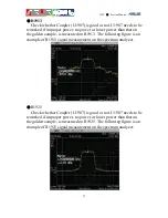
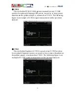
R1925 
Check whether Coupler (U1907) is good or not. U1907 needs to be 

reworked if improper power, no power or lower power than that on 
the golden sample, is measured on R1925. The following figure is an 
example of R1925 signal measurement on the spectrum analyzer. 


Summary of Contents for P552W

Page 1: ...GTC Service Manual 1 華 華碩 碩電 電腦 腦 P552W Level 3 4 Trouble Shooting Guide Ver 1 0 ...

Page 2: ...ion 11 1 4 1 FRONT SIDE 11 1 4 2 BACK SIDE 12 1 5 On Board Major Components Location 13 1 5 1 FRAON SIDE 13 1 5 2 BACKT SIDE 14 1 6 Debugging Equipments 16 2 Baseband Trouble Shooting 2 1 Introduction 19 2 2 Device Cannot Power On 19 2 2 1 Measure each power on sequence voltage level 19 2 2 2 RTC can t power on issue 21 2 3 Device Peripheral Trouble Shooting MMI Testing 22 2 3 1 LCD Display Test 2...

Page 3: ...ck diagram 40 3 3 Procedures of RF Repair 40 3 3 1 GSM and WCDMA repair procedures 40 3 3 2 Bluetooth and WLAN repair procedure 42 3 3 3 GPS repair procedure 43 3 4 General GSM debug 44 3 4 1 GSM path and test points 44 3 4 2 GSM Tx debug 48 3 4 3 GSM Rx debug 58 3 5 General WCDMA debug 64 3 5 1 WCDMA path and test points 64 3 5 2 WCDMA Tx debug 67 3 5 3 WCDMA Rx debug 75 3 6 General Bluetooth and...

Page 4: ...碩 碩電 電腦 腦 Appendix 1 Bluetooth Debug Tool Operation 101 2 WLAN Debug Tool Operation 104 3 GPS Debug Tool Operation GPSinformation_en 109 4 GPS Firmware Download Tool Operation GPSDL 111 5 GPS Debug Tool Operation SiRFDemo 113 ...

Page 5: ...GTC Service Manual 5 華 華碩 碩電 電腦 腦 1 OVERVIEW 1 1 System Block Diagram ...

Page 6: ...GTC Service Manual 6 華 華碩 碩電 電腦 腦 1 2 power on sequence 1 2 1 Start up Timing Diagram ...

Page 7: ...GTC Service Manual 7 華 華碩 碩電 電腦 腦 1 2 2 Start up Timing Parameters 1 2 3 Power on Sequence Summary ...

Page 8: ...hdog monitoring circuit Failure to issue the initial watchdog write will result in shut down of the DA9035 to the power down state Once in the ACTIVE state the EXT_WAKEUP signal will be asserted while the nONKEY nEXTON or VCHG_DETECT are asserted after de bouncing otherwise it is held low All I Os of the DA9035 connected to the host processor will be released at the end of the 32 ms countdown 1 2 ...

Page 9: ...GTC Service Manual 9 華 華碩 碩電 電腦 腦 1 2 5 POWER UP TIMING SPECIFICATIONS 1 2 1 2 6 POWER UP TIMING SPECIFICATIONS 2 2 ...

Page 10: ...RF Star III Display 2 8 QVGA 240 x 320 65K TFT Camera 2 Mega Pixel Fixed Focus Battery 1100mAh Lithium Weight Around 105g with battery Standby Time 3G 150 hours 2G 150 hours Talk Time 3G 3 hours 2G 5 hours Expansion Slot Micro SD support SDHC Browser HTTP WAP 1 2 1 2 0 Messaging SMS MMS Email MSN Push E mail Video Record MPEG4 QVGA 24fps H 263 QCIF 24fps Playback MPEG4 QVGA 30fps H 263 QCIF 30fps ...

Page 11: ...nual 11 華 華碩 碩電 電腦 腦 1 4 Device exterior description 1 4 1 FRONT SIDE NO FUNCTION 1 POWER BUTTON 2 FUNCTION LED 3 LCD 4 CALL KEY 5 AnyTime Launcher KEY 6 JOY DIAL BUTTON 7 OK KEY 8 END KEY 9 GPS PORT 10 VOLUME BUTTON ...

Page 12: ...GTC Service Manual 12 華 華碩 碩電 電腦 腦 1 4 2 BACK SIDE NO FUNCTION 11 SPEAKER 12 2M CAMERA 13 BATTERY COVER 14 TOUCH PEN 15 HOLD KEY 16 CAMERA KEY 17 RESET BUTTON 18 MiniUSB PORT ...

Page 13: ...GTC Service Manual 13 華 華碩 碩電 電腦 腦 1 5 On Board Major Components Location 1 5 1 FRAON SIDE ...

Page 14: ...GTC Service Manual 14 華 華碩 碩電 電腦 腦 1 5 2 BACKT SIDE ...

Page 15: ...GTC Service Manual 15 華 華碩 碩電 電腦 腦 ...

Page 16: ...GTC Service Manual 16 華 華碩 碩電 電腦 腦 1 6 Debugging Equipments Oscilloscope Soldering Iron ...

Page 17: ...GTC Service Manual 17 華 華碩 碩電 電腦 腦 Power Supply Reheat fan ...

Page 18: ...GTC Service Manual 18 華 華碩 碩電 電腦 腦 Voltmeter ...

Page 19: ...lease hook the power supply and check if there is any current If there is no current observed on power supply please push the power button to power on the system first and follow the following debugging process V_BAT power supply voltage 2 2 1 Measure each power on sequence voltage level A V_BAT power supply voltage check C1103 1 This is to make sure that the power source is at the correct level I...

Page 20: ...ower domains If SYS_EN voltage level is incorrect it is likely there is a defect on the CPU U301 F VCC_MVT R515 1 8V VBUCK3 C943 1 2 1V VCC_MVT_PLL_CORE R525 1 8V VCC_MVT_CLK R528 1 8V LDO2 R927 1 8V LDO3 R931 2 8V If incorrect voltage is measured on the above power domains please check if there is any defect on U901 L903 U301 U41 L8 L9 L10 and the surrounding components G PWR_EN U304 2 2 9V PWR_E...

Page 21: ... the oscilloscope to measure R433 OneNAND_nCS and observe if there is any high low transition If not it is likely there is a defect on U601 or U301 If high low transition on R433 can be observed please measured TP610 SD0 and verify if it also have high low transition If not it is likely that there is a defect on U605 2 2 2 RTC can t power on issue Please check the following point if it is all matc...

Page 22: ...evel on super cap down to 0 4V Summary Measurement Check list for device unable to power on a VCC_BBAT b nHWRST_OUT_R c nBATT_LOW d 32KHz TXTAL_IN e SYS_EN f VCC_MVT g SYS_EN Power Group VCC_MVT VBUCK3 VCC_MVT_PLL_CORE VCC_MVT_CLK LDO2 LDO3 h PWR_EN i PWR_SDA PWR_SCL j V_APP V_COMM k 26MHz l OneNAND_nCS m SD0 2 3 Device Peripheral Trouble Shooting MMI Testing 2 3 1 LCD Display Test This test item ...

Page 23: ...ld be 12V If backlight is abnormal please check U1503 and the component around it 2 3 2 Vibrator Test If the vibrator is not functioning please check if VIBRA_C0 voltage is measured at 3V and also no defect is found on component R1516 or D1501 then it is likely that U1505 is defective Figure 1 2 Vibrator mechanism 2 3 3 RTC Test It is rare to observe this type of defect but if it does occur please...

Page 24: ... the sub board If not make sure that sub board and main board BTOB connector are not defective D Please verify if VCC_MMC 2 9V on the sub board If not it is likely that U4 is defective Figure 1 3 microSD Power 2 3 6 LED Test Two type of LED are tested here One is the RGB LED the other one is the Keypad LED If the RGB LED is not functioning properly please follow the following debugging procedure A...

Page 25: ...not then it is likely U1 is defective Figure 1 5 Keypad LED Power 2 3 7 3M and VGA camera Test If the 3M or VGA camera is not functioning properly first try to replace the device with a new camera first if this does not solve the problem please follow the below debugging procedure A Verify if COM_2 8V 2 8V B Verify if V_LD02 1 8V power domain for 3M camera auto focus motor ...

Page 26: ...anual 26 華 華碩 碩電 電腦 腦 Figure 1 6 Camera power 3M_PWRDN 0V 3M_nRESET 1 8V Check if any of the components on figure 7 and figure 8 is defected Check VSYNC HSYNC PCLK has the high low transaction Figure 1 7 Camera Bus ...

Page 27: ... main board BtoB connector CON1201 V_LDO should able to supply 1 8V or 3 3V supplies depending on the SIM card If the measure voltage is incorrect it is likely that U901 is defective During SIM card initialization period SIM_RST voltage level should be measured at 1 8V or 3 3 V SIM_CLK should be able to observe a clock signal and SIM_DAT should be able to observe a high low transition signal If an...

Page 28: ...battery correctly or the incorrect battery reading is observed please examining the following Unable to charge the battery Verify if CHARGER_LDO_18V U408 4 1 8V Verify if AC_USB_VCC R180 5V Verify if PSEL 2 8V if not it is likely that U301 is defective If all the above measurements are correct it is likely that U1101 is defective ...

Page 29: ...attery information Verify if 1 WIRE sends out signal periodically Verify if R1107 is still mounted properly Verify if 1 8V can be measured on V_LDO2 measured If any of above signal is incorrect please check if CPU U301 or PMU U901 is defective Figure 1 11 Battery Information Circuit ...

Page 30: ...observe this type of defect but if this does occur it is likely that U601 is defective Figure 1 12 SDRAM Circuit 2 3 11 Audio Test 2 3 11 1 Headset Defect Please check if there is any external damage to the headphone connector first if not please verifies the following ...

Page 31: ... the sound through headphone If the audio signal can be measured on C1117 and R1127 but can not be observed on R1135 then it is likely that U1102 is defective No sound on the right channel Verify if R1134 R1126 C1118 is defective and that audio signal can be measured on above components when playing the sound through headphone If the audio signal can be measured on C1118 and R1126 but can not be o...

Page 32: ...ing procedure Verify if measured 3 6V is correct and R1021 both end s measured voltage is 3 6V Verify if there is any defect on components R1034 R1036 R1037 R1038 C1010 C1011 R1024 R1020 and observe if audio signal can be measured on those components when playing sounds through speaker If audio signal can be measured on R1034 R1036 R1037 R1038 but can not be measured on R1024 and R1020 then it is ...

Page 33: ...he below debugging procedure a Speaker have no sound 1 Check the power 3 6V 2 then check both side of R1024 and R1020 if there is any high low transaction 3 Check SPK_SHDN R1340 it should be high 2 8V 4 if signal could be measured on SPKL SPKR but R1024 R1020 have no signal then U1003 Class D Amp NG change U1003 We have found many speaker issue on this U1003 component ...

Page 34: ...電腦 腦 Figure 1 14 Class D Amp for speaker b On Board Microphone record fail If recording performance is not good U1002 NG If no recording signal measured then check the related component1003 C1004 C1005 R1016 C1006 R1018 C1009 C1007 ...

Page 35: ...3 C1042 C1034 If these are all ok check related balls of U901 Figure 1 17 Receiver Circuit 2 3 12 Touch Panel Defect Verify if touch panel s FPC is connected properly onto the connector on the keypad board Verify if keypad board is defective by replacing a new keypad Verify if touch panel is defective by replacing a new panel ...

Page 36: ...ol WLAN test tool Bluetooth test tool GSP test tool 3 1 2 Hardware requirements RF adapter RF cable USB cable 3 1 3 Instrument requirements PC Wireless communication test set Agilent 8960 R S CMU9020 Anritsu 8820 GPS signal simulator GPS101 STR4500 Spectrum analyzer Span 3 0 GHz RF signal generator up to 3 0 GHz High impedance RF probe with DC block Oscilloscope Digital multimeter Power supply ...

Page 37: ...GTC Service Manual 37 華 華碩 碩電 電腦 腦 3 2 RF Block Diagram 3 2 1 GSM block diagram ...

Page 38: ...GTC Service Manual 38 華 華碩 碩電 電腦 腦 3 2 2 WCDMA block diagram ...

Page 39: ...GTC Service Manual 39 華 華碩 碩電 電腦 腦 3 2 3 Bluetooth and WLAN block diagram ...

Page 40: ...rsion image also called as OS or firmware should be downloaded for RF calibration and backup calibration files Calibrating GM2 or backup calibration files might encounter some problems under ship version images GM2 can be judged good RF performance after passing conductive pretest There are four kinds of general RF debug about GSM and WCDMA phone functions including GSM Tx debug GSM Rx debug WCDMA...

Page 41: ...GTC Service Manual 41 華 華碩 碩電 電腦 腦 ...

Page 42: ...h and WLAN repair procedure The following flow chart shows BT Bluetooth and WLAN Wireless local area network repair s procedures Both BT and WLAN need debug tool to enforce module into test mode The operation of debug tool is described in the appendix ...

Page 43: ...neral GPS debug is necessary if GPS conductive test is failed There are three types of GPS debug methods in the general GPS debug stage including GPS DC debug verifying DC power supply and reference clock GPS firmware download installing firmware on GPS chip and GPS RF debug checking defect component on the GPS RF path ...

Page 44: ...h RF signal is transmitted depends on band selection of FEM U1804 In the low band output signal from B6PLD Pin J7 passes through C1844 and RPF09036B U1803 Pin7 power amplifier sequentially Pin25 of front end module U1804 also abbreviated to FEM gets the amplified signal from RPF09036B Pin13 FEM Pin19 transmits RF signal to RF connector CON1801 and the signal is radiated via the antenna In the high...

Page 45: ...cuits and B6PLD U1802 sequentially The incoming RF signal is mixed directly down to digital I Q signals by B6PLD U1802 and transmit I Q sampling data to baseband In PCS1900 band the RF signal from FEM U1804 Pin7 and Pin8 is transmitted to Rx differential matching circuits and B6PLD U1802 sequentially The incoming RF signal is mixed directly down to digital I Q signals by B6PLD U1802 and transmit I...

Page 46: ...GTC Service Manual 46 華 華碩 碩電 電腦 腦 ...

Page 47: ...GTC Service Manual 47 華 華碩 碩電 電腦 腦 GSM test points ...

Page 48: ...GTC Service Manual 48 華 華碩 碩電 電腦 腦 3 4 2 GSM Tx debug The flow chart of GSM Tx debug is shown below ...

Page 49: ...mpedance probe Execute WCDMA debug tool and set parameters in the above table b Use a multimeter to check that each component on Tx path is fed correct voltage level The following table shows component s location number DC test point and typical voltage level c Use the high impedance probe to sequentially measure RF power of test points on GSM DCS PCS Tx path including C1842 C1844 C1836 C1839 C180...

Page 50: ...iver B6PLD U1802 operates normally or not U1802 needs to be replaced if improper RF power no power or lower power than that on the golden sample is measured on C1844 and C1842 C1844 is the test point for GSM900 band C1842 is the test point for DCS1800 and PCS1900 band The following figures which sequentially indicate measurement result of GSM900 on C1844 and DCS1800 PCS1900 on C1842 are examples o...

Page 51: ...GTC Service Manual 51 華 華碩 碩電 電腦 腦 DCS1800 PCS1900 ...

Page 52: ...r lower power than that on the golden sample is measured on C1836 and C1839 C1836 is the test point for GSM900 band C1839 is the test point for DCS1800 and PCS1900 band The following figures which sequentially indicate measurement result of GSM900 on C1836 and DCS1800 PCS1900 on C1839 are examples of RF signal easurement on the spectrum analyzer GSM900 ...

Page 53: ...GTC Service Manual 53 華 華碩 碩電 電腦 腦 DCS1800 PCS1900 ...

Page 54: ...r RF power no power or lower power than that on the golden sample is measured on C1806 C1806 is the test point for GSM900 band DCS1800 and PCS1900 band The following figures which sequentially indicate measurement result of GSM900 DCS1800 and PCS1900 on C1806 are examples of RF signal measurement on the spectrum analyzer GSM900 ...

Page 55: ...GTC Service Manual 55 華 華碩 碩電 電腦 腦 DCS1800 PCS1900 ...

Page 56: ...801 needs to be reworked if improper power no power or lower power than that on the golden sample is measured on R1833 The following figures which sequentially indicate measurement result of GSM900 DCS1800 and PCS1900 on R1833 are examples of RF signal measurement on the spectrum analyzer GSM900 ...

Page 57: ...GTC Service Manual 57 華 華碩 碩電 電腦 腦 DCS1800 PCS1900 ...

Page 58: ...GTC Service Manual 58 華 華碩 碩電 電腦 腦 3 4 3 GSM Rx debug The flow chart of GSM Rx debug is shown below ...

Page 59: ... 162 Spectrum analyzer connects with a high impedance probe Execute GSM debug tool and set parameters in the above table b Use a multimeter to check that each component on Rx path is fed correct voltage level The following table shows component s location number DC test point and typical voltage level c Use the high impedance probe to sequentially measure RF power generated by the signal generator...

Page 60: ...s C1806 Check whether RF Connector CON1801 is good or not CON1801 needs to be reworked if improper power no power or lower power than that on the golden sample is measured on C1806 The following figures which sequentially indicate measurement result of GSM900 DCS1800 and PCS1900 on R1833 are examples of RF signal measurement on the spectrum analyzer GSM900 ...

Page 61: ...GTC Service Manual 61 華 華碩 碩電 電腦 腦 GSM1800 GSM1900 ...

Page 62: ... that on the golden sample is measured on C1831 C1821 and C1810 C1831 is the test point for GSM900 band C1821 is the test point for DCS1800 and C1810 is the test point for PCS1900 band The following figures which sequentially indicate measurement result of GSM900 on C1831 DCS1800 on C1821 and PCS1900 on C1810 are examples of RF signal measurement on the spectrum analyzer GSM900 ...

Page 63: ...GTC Service Manual 63 華 華碩 碩電 電腦 腦 GSM1800 GSM1900 ...

Page 64: ...e to coupler One travels to duplexer U1903 Pin7 and the other is transmitted to power detector U1912 The former passes through duplexer U1903 Pin2 FEM U1804 and the connector CON1801 sequentially At last the RF signal is radiated via the antenna of GM2 WCDMA Rx path Incoming RF signal from base stations via the WCDMA antenna passes through connector CON1801 and duplexer U1903 Pin5 sequentially LNA...

Page 65: ...GTC Service Manual 65 華 華碩 碩電 電腦 腦 ...

Page 66: ...GTC Service Manual 66 華 華碩 碩電 電腦 腦 WCDMA test points ...

Page 67: ...GTC Service Manual 67 華 華碩 碩電 電腦 腦 3 5 2 WCDMA Tx debug The flow chart of WCDMA Tx debug is shown below ...

Page 68: ...GTC Service Manual 68 華 華碩 碩電 電腦 腦 The purpose of Tx debug process is to find out where the problem is on ...

Page 69: ...ove table b Use a multimeter to check that each component on Tx path is fed correct voltage level The following table shows component s location number DC test point and typical voltage level c Use the high impedance probe to sequentially measure RF power of test points on WCDMA Tx path including L1906 C1921 C1946 R1913 R1925 C1824 C1806 and R1833 Corresponding locations of test points are shown i...

Page 70: ...are showed in the following descriptions L1906 Check whether Transceiver PMB5701 U1901 operates normally or not U1901 needs to be replaced if improper RF power no power or lower power than that on the golden sample is measured on L1906 The following figure is an example of L1906 signal measurement on the spectrum analyzer ...

Page 71: ...le is measured on C1921 The following figure is an example of C1921 signal measurement on the spectrum analyzer C1946 Check whether PA AWT6241 U1906 operates normally or not U1906 needs to be replaced if improper RF power no power or lower power than that on the golden sample is measured on C1946 The following figure is an example of C1946 signal measurement on the spectrum analyzer ...

Page 72: ...en sample is measured on R1913 The following figure is an example of R1913 signal measurement on the spectrum analyzer R1925 Check whether Coupler U1907 is good or not U1907 needs to be reworked if improper power no power or lower power than that on the golden sample is measured on R1925 The following figure is an example of R1925 signal measurement on the spectrum analyzer ...

Page 73: ...ample is measured on C1824 The following figure is an example of C1824 signal measurement on the spectrum analyzer C1806 Check whether FEM U1804 operates normally or not U1804 needs to be replaced if improper RF power no power or lower power than that on the golden sample is measured on C1806 The following figure is an example of C1806 signal measurement on the spectrum analyzer ...

Page 74: ...ther RF Connector CON1801 is good or not CON1801 needs to be reworked if improper power no power or lower power than that on the golden sample is measured on R1833 The following figure is an example of R1833 signal measurement on the spectrum analyzer ...

Page 75: ...GTC Service Manual 75 華 華碩 碩電 電腦 腦 3 5 3 WCDMA Rx debug The flow chart of WCDMA Rx debug is shown below ...

Page 76: ...ia a RF cable and a RF adapter MS 162 Spectrum analyzer connects with a high impedance probe Execute WCDMA debug tool and set parameters in the above table b Use a multimeter to check that each component on Rx path is fed correct voltage level The following table shows component s location number DC test point and typical voltage level c Use the high impedance probe to sequentially measure RF powe...

Page 77: ...f measured RF signals on each test point are showed in the following escriptions C1806 Check whether RF Connector CON1801 is good or not CON1801 needs to be reworked if improper power no power or lower power than that on the golden sample is measured on C1806 The following figure is an example of C1806 signal measurement on the spectrum analyzer ...

Page 78: ...golden sample is measured on C1824 The following figure is an example of C1824 signal measurement on the spectrum analyzer C1943 Check whether Duplexer U1903 is good or not U1903 needs to be reworked if improper power no power or lower power than that on the golden sample is measured on C1943 The following figure is an example of C1943 signal measurement on the spectrum analyzer ...

Page 79: ... SAW filter U1908 operate normally or not Either U1911 or U1908 needs to be replaced if improper RF power no power or lower power than that on the golden sample is measured on L1911 The following figure is an example of L1911 signal measurement on the spectrum analyzer ...

Page 80: ...nts Bluetooth and WLAN share the same RF circuits from the chip antenna U1702 to combiner U1706 Bluetooth and WLAN path Bluetooth and WLAN RF signals come from BT WLAN combo module U804 Both Bluetooth and WLAN signals are transmitted to combiner U1706 and then radiated via chip antenna U1702 on the top side of PCB ...

Page 81: ...GTC Service Manual 81 華 華碩 碩電 電腦 腦 Bluetooth and WLAN test points ...

Page 82: ...cess is to find out where the problem is on Bluetooth and WLAN path In other words engineers can judge the defect component on RF path by using BT Debug tool and WLAN Debug tool Debug tool enforces GM2 BT or WLAN function into test mode so that RF signal can be transmitted continuously The usage of debug tool and its related parameters are prescribed in the appendix ...

Page 83: ...nal pads Corresponding locations of test points are shown in Bluetooth and WLAN test points Measurement error of RF power on each test point is unavoidable due to measurement skills and operating methods of using high impedance probe Moreover measured RF signal strength of each point must refer to a golden sample under the same measurement conditions The results of measured RF signals on each test...

Page 84: ...is measured on C1711 The following figure is an example of C1711 Bluetooth signal measurement on the spectrum analyzer b WLAN R1767 Check whether combo module U804 operates normally or not U804 needs to be replaced if improper RF power no power or lower power than that on the golden sample is measured on R1767 The following figure is an example of R1767 signal measurement on the spectrum analyzer ...

Page 85: ...combiner U1706 operates normally or not U1706 needs to be replaced if improper RF power no power or lower power than that on the golden sample is measured on C1711 The following figure is an example of C1711 WLAN signal measurement on the spectrum analyzer ...

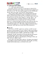
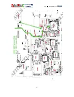
Page 86: ...w GPS chip on PCB Moreover a download problem sometimes may result from CPLD or CPU but not from the GPS chip itself The last debug method is GPS RF performance test This debug method is to find out defect components on RF path and to ensure good GPS performance GPS path GM2 receives GPS RF signals from satellites via GM2 internal antenna or external antenna or active antenna When using internal a...

Page 87: ...GTC Service Manual 87 華 華碩 碩電 電腦 腦 ...

Page 88: ...GTC Service Manual 88 華 華碩 碩電 電腦 腦 GPS test points ...

Page 89: ...GTC Service Manual 89 華 華碩 碩電 電腦 腦 3 7 2 GPS debug The flow charts of GPS debug are shown below ...

Page 90: ...GTC Service Manual 90 華 華碩 碩電 電腦 腦 ...

Page 91: ...GTC Service Manual 91 華 華碩 碩電 電腦 腦 ...

Page 92: ...GTC Service Manual 92 華 華碩 碩電 電腦 腦 ...

Page 93: ...eover engineers need a debug tool also called as GPSinformation_en to enforce GPS chip into test mode and then all power supplies and reference clocks TCXO and RTC are enable Under GPS test mode power domain including LDO power switch and four voltage regulators of U2001 can be measured by a multimeter In addition GPS on off trigger mechanism and two clocks TCXO and RTC can be measured by an oscil...

Page 94: ...o be replaced if no proper clock is measured on corresponding test point d Use a multimeter to check output voltage level from LDO U2010 power switch U2008 and four voltage regulators of U2001 LDO U2010 power switch U2008 or U2001 need to be replaced if no proper voltage level is measured on corresponding test points The following table shows component s location number DC test point and typical v...

Page 95: ... status Start GPS or Close GPS is listed in the following table U2001 needs to be replaced if no pulse signal or proper voltage is measured on R2021 or R2023 respectively The following figures are examples showing pulse signals when pressing Start GPS and Close GPS R2021 Start GPS R2021 Close GPS ...

Page 96: ...process is GPS firmware download The purpose of this process is to ensure that GPS chip U2001 can be refreshed new firmware Failure in firmware download may result from CPU or GPS chip itself R2022 pulls high voltage level while downloading GPS firmware The detail steps of GPS firmware download are listed as follows a Execute GPS firmware download tool on GM2 The usage of GPS firmware download too...

Page 97: ...ted in the following table b Execute SiRFDemo debug tool and related parameters of this debug tool are prescribed in the appendix Measure C N value by using SiRFDemo and pass criteria is listed in the above table The following debug processes are necessary if C N measurement fail the criteria c Spectrum analyzer connects with a high impedance probe and set frequency as it in the above table d Use ...

Page 98: ...olden sample is measured on C2010 The following figure is an example of C2010 signal measurement on the spectrum analyzer L2003 Check whether SAW filter U2005 is good or not U2005 needs to be reworked if improper power no power or lower power than that on the golden sample is measured on L2003 The following figure is an example of L2003 signal measurement on the spectrum analyzer ...

Page 99: ...ot U2007 needs to be reworked if improper power no power or lower power than that on the golden sample is measured on R2005 The following figure is an example of R2005 signal measurement on the spectrum analyzer R2027 Check whether SAW filter U2006 is good or not U2006 needs to ...

Page 100: ...nual 100 華 華碩 碩電 電腦 腦 be reworked if improper power no power or lower power than that on the golden sample is measured on R2027 The following figure is an example of R2027 signal measurement on the spectrum analyzer ...

Page 101: ...華碩 碩電 電腦 腦 Appendix 1 Bluetooth Debug Tool Operation Step1 Install GM2_BT_TEST CAB on GSM and then generate CSR_BT_TEST debug tool in My Documents folder Execute CSR_BT_TEST Step2 Click Turn On Test Mode in the Test Mode sheet ...

Page 102: ...GTC Service Manual 102 華 華碩 碩電 電腦 腦 Step3 Enter frequency and power level in the TxStart sheet Step4 Press Start and RF signal is transmitted ...

Page 103: ...GTC Service Manual 103 華 華碩 碩電 電腦 腦 Step5 Click Re Test to stop transmit RF power Step6 Click Close AP to close debug tool ...

Page 104: ...GTC Service Manual 104 華 華碩 碩電 電腦 腦 2 WLAN Debug Tool Operation Step1 Install EnableWiFiMFG_NoBCA CAB on GM2 Step2 After installing WLAN debug tool reboot GM2 ...

Page 105: ...GTC Service Manual 105 華 華碩 碩電 電腦 腦 Step3 Click Wi Fi once time in the Wireless Manager Step4 Execute MfgUtility_NoBCA debug tool in Programs folder ...

Page 106: ...GTC Service Manual 106 華 華碩 碩電 電腦 腦 Step5 Choose Info and then press Select Step6 Check the version of debug tool like below and then press Exit ...

Page 107: ...GTC Service Manual 107 華 華碩 碩電 電腦 腦 Step7 Choose Tx and then press Select Step8 Choose WLAN parameters like below and then press Start in the Menu to transmit RF power ...

Page 108: ...GTC Service Manual 108 華 華碩 碩電 電腦 腦 Step9 Choose Stop in the Menu to stop RF signal and then press Exit to close WLAN debug tool ...

Page 109: ...e Manual 109 華 華碩 碩電 電腦 腦 3 GPS Debug Tool Operation GPSinformation_en Step1 Execute GPSinformation_en on GM2 Step2 Choose GPS parameters like below Step3 Press Start GPS to enter GPS test mode and enable all GPS ...

Page 110: ...GTC Service Manual 110 華 華碩 碩電 電腦 腦 voltage supplies and clocks Step4 Press Close GPS to disable GPS test mode ...

Page 111: ...GTC Service Manual 111 華 華碩 碩電 電腦 腦 4 GPS Firmware Download Tool Operation GPSDL Step1 Choose GPS_AP folder Step2 Execute GPSDL to download GPS firmware ...

Page 112: ...GTC Service Manual 112 華 華碩 碩電 電腦 腦 Step3 This screen shows that GPS firmware is downloading Step4 GPSDL exits automatically when firmware download completing ...

Page 113: ...GTC Service Manual 113 華 華碩 碩電 電腦 腦 5 GPS Debug Tool Operation SiRFDemo Step1 Execute SiRFDemo on GM2 Step2 Press ok ...

Page 114: ...GTC Service Manual 114 華 華碩 碩電 電腦 腦 Step3 Choose GSW3 and then press ok Step4 Choose GPS parameters like below ...

Page 115: ...GTC Service Manual 115 華 華碩 碩電 電腦 腦 Step5 Press Connect and wait for connetion Step6 Press Done after successful connection Step7 Choose Signal page ...

Page 116: ...GTC Service Manual 116 華 華碩 碩電 電腦 腦 Step7 Satellite number and C N value show up when GPS signal is received by GPS chip successfully Step8 Choose Setup menu to exit SiRFDemo ...

Page 117: ...GTC Service Manual 117 華 華碩 碩電 電腦 腦 Step9 Press Exit ...

Reviews: