background image

14

ASUS P4T-F User’s Manual

3. HARDWARE SETUP

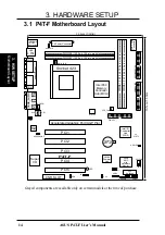
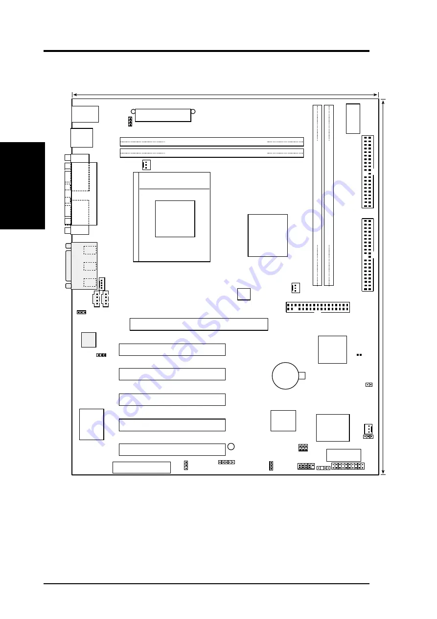
3.1 P4T-F Motherboard Layout

Grayed components are available only on certain models at the time of purchase.

Motherboard Layout

3.  H/W SETUP

24.4cm (9.60in)

30.5cm (12.0in)

PS/2KBMS

T: Mouse
B: Keyboard

MAIN_FAN

CHASSIS

PANEL

FLOPPY

SECONDAR

Y

 IDE

PRIMAR

Y

 IDE

Intel I/O

Controller

Hub

(ICH2)

P4T-F

PCI_FAN

DIP

Switches

LED

Accelerated Graphics Port (AGP Pro)

ASUS

ASIC

with

Hardware

Monitor

CR2032 3V
Lithium Cell

CMOS Power

CLRTC

Socket 423

USB

T: Port1
B: Port2

COM1

P

ARALLEL

 PORT

COM2

Intel 850

Memory

Controller

Hub (MCH)

ATX Power Connector

2Mbit

Firmware

Hub

USB2

RIMMA

1

 (16/18 bit, 184-pin module)

Super

I/O

AUX Power

 Connector

CPU_FAN

ATX12V

USBPWR

JEN

IR

PCI1

PCI2

PCI3

PCI4

PCI5

RIMMA2 (16/18 bit, 184-pin module)

RIMMB2 (16/18 bit, 184-pin module)

RIMMB1 (16/18 bit, 184-pin module)

CNR_SLOT

J3-

ADN

J3+

OC3

AUX

MODEM

MIC2

HEADPHONE

GAME_AUDIO

Mic

In

Line
Out

Line

In

Audio

Codec

CD1

HDDLED

Summary of Contents for P4T-F

Page 1: ... P4T F Intel 850 ATX Motherboard USER S MANUAL ...

Page 2: ...er of the product is defaced or missing Products and corporate names appearing in this manual may or may not be registered trade marks or copyrights of their respective companies and are used only for identification or explanation and to the owners benefit without intent to infringe Adobe and Acrobat are registered trademarks of Adobe Systems Incorporated Intel LANDesk and Pentium are registered t...

Page 3: ... pub ASUS ASUS COMPUTER INTERNATIONAL America Marketing Address 6737 Mowry Avenue Mowry Business Center Building 2 Newark CA 94560 USA Fax 1 510 608 4555 Email tmd1 asus com Technical Support Fax 1 510 608 4555 Email tsd asus com WWW www asus com FTP ftp asus com Pub ASUS ASUS COMPUTER GmbH Europe Marketing Address Harkortstr 25 40880 Ratingen BRD Germany Fax 49 2102 442066 Email sales asuscom de ...

Page 4: ...le Installation 26 3 6 Expansion Cards 29 3 6 1 Installing an Expansion Card 29 3 6 2 Assigning IRQs for Expansion Cards 30 3 8 External Connectors 32 3 9 Starting Up the First Time 43 4 BIOS SETUP 45 4 1 Managing and Updating Your BIOS 45 4 1 1 Upon First Use of the Computer System 45 4 1 2 Updating BIOS Procedures 46 4 2 BIOS Setup Program 49 4 2 1 BIOS Menu Bar 50 4 2 2 Legend Bar 50 4 3 Main M...

Page 5: ...u 72 4 7 Exit Menu 74 5 SOFTWARE SETUP 77 5 1 Install Operating System 77 5 2 Start Windows 77 5 3 P4T F Motherboard Support CD 78 6 SOFTWARE REFERENCE 80 6 1 ASUS Live Update 80 6 2 ASUS PC Probe 81 6 3 CyberLink PowerPlayer SE 86 6 4 CyberLink VideoLive Mail 87 7 APPENDIX 89 7 1 Glossary 89 INDEX 95 ...

Page 6: ... the equipment off and on the user is encouraged to try to correct the interfer ence by one or more of the following measures Re orient or relocate the receiving antenna Increase the separation between the equipment and receiver Connect the equipment to an outlet on a circuit different from that to which the receiver is connected Consult the dealer or an experienced radio TV technician for help WA...

Page 7: ... items and general reference 1 2 Item Checklist Check that your package is complete If you discover damaged or missing items contact your retailer 1 INTRODUCTION 1 INTRODUCTION Manual Checklist Optional Items ASUS IrDA compliant infrared module Rambus LAN Card 1394 Card Package Contents 1 ASUS Motherboard 1 40 pin 80 conductor ribbon cable for internal UltraDMA33 66 100 IDE drives 1 Ribbon cable f...

Page 8: ...igh bandwidth is required Intel Accelerated Hub Architecture Features a dedicated high speed hub link between the ICH2 and MCH with a bandwidth of 266MB sec twice the maximum bandwidth of the PCI bus AGP Pro Slot Comes with an Accelerated Graphics Port Pro slot that supports AGP cards for high performance component level interconnect targeted at 3D graphical applications using a 4X mode bus The sl...

Page 9: ...enium compat ibility built in firmware based virus protection and autodetection of most de vices for virtually automatic setup Smart BIOS 2Mbit firmware gives a new easy to use interface for more control and protection for the motherboard Supports Vcore and CPU RDRAM frequency adjustments boot block write protection and HD SCSI MO ZIP CD Floppy boot selection IrDA Supports an optional infrared por...

Page 10: ... implemented on all ASUS smart series motherboards ACPI provides more Energy Saving Features for future operating systems OS supporting OS Direct Power Management OSPM functionality With these features implemented in the OS PCs can be ready around the clock yet satisfy all the energy saving standards To realize the benefits of ACPI an ACPI supported OS such as Windows 98 2000 Millenium must be use...

Page 11: ...board components Voltage specifications are more critical for future processors so monitoring is necessary to ensure proper system configuration and management System Resources Alert Today s operating systems such as Windows 98 Millenium and Windows NT 2000 require much more memory and hard drive space to present enormous user interfaces and run large applications The onboard hardware ASUS ASIC in...

Page 12: ...NR 15 System I O 2 IDE Connectors UltraDMA33 66 100 support 7 1 Floppy Disk Drive Connector 8 1 USB Header supports 2 USB ports 12 1 Parallel Port Connector Top 24 1 Serial COM1 Port Connector Bottom 25 1 Serial COM2 Port Connector Bottom 23 2 USB Port Connectors 26 1 PS 2 Mouse Connector Top 27 1 PS 2 Keyboard Connector Bottom 27 Audio Headphone Connector 18 AC 97 Audio CODEC 19 Microphone 2 Conn...

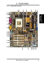
Page 13: ...ASUS P4T F User s Manual 13 2 FEATURES 2 FEATURES Component Locations 2 2 1 Component Locations 2 14 8 13 17 20 12 24 25 26 27 22 5 11 7 4 6 10 9 1 3 15 16 19 23 18 21 ...

Page 14: ...Accelerated Graphics Port AGP Pro ASUS ASIC with Hardware Monitor CR2032 3V Lithium Cell CMOS Power CLRTC Socket 423 USB T Port1 B Port2 COM1 PARALLEL PORT COM2 Intel 850 Memory Controller Hub MCH ATX Power Connector 2Mbit Firmware Hub USB2 RIMMA1 16 18 bit 184 pin module Super I O AUX Power Connector CPU_FAN ATX12V USBPWR JEN IR PCI1 PCI2 PCI3 PCI4 PCI5 RIMMA2 16 18 bit 184 pin module RIMMB2 16 1...

Page 15: ...p 33 Universal Serial Bus Ports Two 4 pin female 6 GAME_AUDIO p 34 Joystick MIDI Connector 15 pin female optional 7 LINE IN OUT MIC p 34 Audio Port Connectors Three 1 8 female optional 8 FLOPPY p 34 Floppy Disk Drive Connector 34 1pin 9 PRIMARY SECONDARYIDE p 35 Primary Secondary IDE Connectors Two 40 1 pin 10 MAIN_FAN CPU_FAN p 36 Fan Connectors Three 3 pin PCI_FAN 11 USB2 p 37 USB Header 10 1 pi...

Page 16: ...r heavily loaded configurations an ATX12V power supply that can supply at least 300W is required Complete the following steps before using your computer 1 Check motherboard settings 2 Install memory modules 3 Install the Central Processing Unit CPU 4 Install Expansion Cards 5 Connect ribbon cables panel wires and power supply cables 6 Configure the BIOS parameter settings WARNING Make sure that yo...

Page 17: ...ns whenever you work on your computer 1 Unplug your computer when working on the inside 2 Use a grounded wrist strap before handling computer components If you do not have one touch both of your hands to a safely grounded object or to a metal object such as the power supply case 3 Hold components by the edges and try not to touch the IC chips leads or con nectors or other components 4 Place compon...

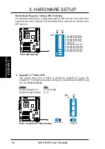
Page 18: ... 1 2 3 4 5 6 7 8 9 10 JEN Jumper Free Default 2 3 OFF SW1 Motherboard Frequency Settings SW1 Switches The motherboard frequency is adjusted through the DIP switches The white block represents the switch s position The illustration below shows all the switches in the OFF position 1 JumperFree Mode JEN This jumper allows you to enable or disable the JumperFree mode The JumperFree mode allows process...

Page 19: ...y the advertised CPU speed P4T F P4T F CPU External Frequency Selection CPU AGP PCI SW1 100 0MHz 66 0MHz 33 0MHz ON 1 2 3 4 5 6 7 8 9 10 103 0MHz 68 0MHz 34 0MHz ON 1 2 3 4 5 6 7 8 9 10 105 0MHz 70 0MHz 35 0MHz ON 1 2 3 4 5 6 7 8 9 10 110 0MHz 73 0MHz 36 0MHz ON 1 2 3 4 5 6 7 8 9 10 Motherboard Settings 3 H W SETUP WARNING Set the CPU frequency only to the recommended settings Frequencies other th...

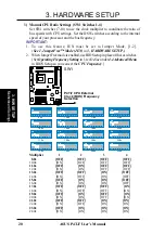
Page 20: ...tches 1 4 Set SW1 switches 7 10 to use the clock multiplier to coordinate the ratio of bus speeds with CPU settings Set the DSW switches according to the internal speed of your processor and the bus frequency IMPORTANT 1 To use this feature JEN must be set to Jumper Mode 1 2 See 1 JumperFree Mode JEN in 3 HARDWARE SETUP 2 When JumperFree mode is enabled use BIOS setup in place of these switches Se...

Page 21: ... allow wake up from S3 sleep state no power to CPU RAM in slow refresh power supply in reduced power mode The default set ting for the three jumpers is 1 2 to select 5V because not all computers have the appropriate power supply NOTES 1 This feature requires an ATX power supply that can supply at least 2A on the 5VSB lead when these jumpers are set to 5VSB Otherwise the system does not power up 2 ...

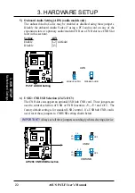
Page 22: ...CNR functions J3 J3 and OC3 The factory default setting is for standard USB2 control If a USB hub CNR card is used reset these jumpers to CNRUSB setting shown below IMPORTANT Always set all three jumpers accordingly when selecting a device 5 Onboard Audio Setting ADN audio models only The onboard Audio Codec may be enabled or disabled using these jumpers Disable the onboard Audio Codec if using a ...

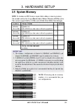
Page 23: ...M use when socket will not be populated RIMMB1 RDRAM x 1 Rows 4 5 C RIMM use when socket will not be populated RIMMB2 RDRAM x 1 Rows 6 7 C RIMM use when socket will not be populated TOTALSYSTEM MEMORY 2GB Max NOTE When using only two memory modules it is recommended that you use configuration a IMPORTANT 1 The memory configuration of channel A RIMMA1 and RIMMA2 and channel B RIMMB1 and RIMMB2 must...

Page 24: ...et s ejectors should go through the two mounting notches on the module and the ejectors should close If necessary push the ejectors inward to secure the mod ule in place Removing Memory To release a memory module push both ejectors outward and pull the module straight up and out of the RIMM sockets WARNING RIMM modules become extremely hot during operation To re duce the risk of personal injury fr...

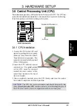
Page 25: ... Then lift the lever upwards The socket lever must be fully opened 90 to 100 degrees 2 Insert the CPU with the correct orientation The gold arrow of the CPU must be oriented toward the outer corner of the socket base nearest to the tip of the lever handle 3 Once completely inserted press the CPU firmly and close the socket lever until it snaps into its locked position CAUTION The CPU fits in one o...

Page 26: ...races have built in retaining clips below left An alternate heatsink support brace with two separate retaining clips may be included with this package below right Both types of supports may be affixed to the motherboard using the plastic plugs and shown in 2 below 2 Four black plastic collars and four white plastic plugs Built in retaining clips Separate retaining clips ...

Page 27: ...locking brace no extra force is required to keep the CPU in place 2 Connect the CPU fan cable to the fan connector See 3 1 Motherboard Layout 3 8 Connectors Step 2a Mount Heatsink Using Built in Retaining Clips CAUTION Take care not to scrape the motherboard surface when mounting a clamp style processor fan or else damage may occur When mounting a heatsink onto your CPU make sure that exposed CPU ...

Page 28: ... base 3 Push down on the levered end of the heatsink retaining clip until it locks into place Step 2b Mount Heatsink Using Separate Retaining Clips 1 Latch the large middle clip on the metal heatsink retainer to the central black tab on the plastic heatsink support base 4 Connect the CPU fan cable to the fan connector See 3 1 Motherboard Layout 3 8 Connectors 3 H W SETUP Heatskink ...

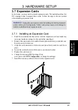
Page 29: ... Installing an Expansion Card 1 Read the documentation that comes with the expansion card and make any necessary hardware settings for the card before installing it 2 Remove the system unit cover and the bracket plate on the slot you intend to use Keep the screw for later use 3 Align the card connectors with the slot and press firmly until the card fits in place 4 Secure the card to the slot with ...

Page 30: ...mmunications Port COM1 5 13 Sound Card sometimes LPT2 6 14 Floppy Disk Controller 7 15 Printer Port LPT1 8 3 System CMOS Real Time Clock 9 4 ACPI Mode when enabled 10 5 IRQ Holder for PCI Steering 11 6 IRQ Holder for PCI Steering 12 7 PS 2 Compatible Mouse Port 13 8 Numeric Data Processor 14 9 Primary IDE Channel 15 10 Secondary IDE Channel These IRQs are usually available for ISA or PCI devices I...

Page 31: ...rly into the new AGP 4X slots See examples of both types below P4T F P4T F Accelerated Graphics Port AGP PRO TOP VIEW Rib inside slot Rib 20 pin bay 28 pin bay AGP Card without Retention Notch An early 3 3V AGP card Do not use A new 1 5 3 3V AGP card OKAY to use P4T F P4T F Communication Networking Riser Connectors 3 7 4 Communications and Networking Riser CNR This connector supports specially des...

Page 32: ...the connectors before installation because there may be exceptions IDE ribbon cables must be less than 46 cm 18 in with the second drive connector no more than 15 cm 6 in from the first connector 1 PS 2 Mouse Connector Green 6 pin PS2KBMS The system will direct IRQ12 to the PS 2 mouse if one is detected If one is not detected expansion cards can use IRQ12 See PS 2 Mouse Function Control in 4 4 Adv...

Page 33: ... 4 pin USB Two USB ports are available for connecting USB devices For additional USB ports you can use the USB headers see USB Headers later in this section NOTE USB Function see 4 4 3 PCI Configuration must be Enabled to use these ports COM2 COM1 Serial Ports 9 pin Male 4 Serial Port Connectors Teal Turquoise 9 pin COM1 9 pin COM2 Two serial ports are ready for a mouse or other serial devices See...

Page 34: ...lows tape players or other audio sources to be recorded by your com puter or played through the Line Out Mic allows microphones to be connected for inputting voice Mic Line In Line Out 1 8 Stereo Audio Connectors 8 Floppy Disk Drive Connector 34 1pin FLOPPY This connector supports the provided floppy drive ribbon cable After connect ing the single end to the board connect the two plugs on the othe...

Page 35: ...fig ure the second drive to Slave mode Please refer to your hard disk documenta tion for the jumper settings BIOS now supports specific device bootup see 4 6 Boot Menu Pin 20 is removed to prevent wrong orientations TIP You may configure two hard disks to be both Masters with two ribbon cables one for the primary IDE connector and another for the secondary IDE connector You may install one operati...

Page 36: ...onnect the fan s plug to the board taking into consid eration the polarity of the connector NOTE The Rotation signal is to be used only by a specially designed fan with rotationsignal TheRotationsperMinute RPM canmonitoredusinga utility such as ASUS PC Probe or Intel LDCM WARNING The CPU and or motherboard will overheat if there is no airflow across the CPU and onboard heatsinks Damage may occur t...

Page 37: ... and mount the USB connector set to an open slot on your chassis P4T F P4T F USB Headers USB2 1 5 6 10 1 USB Power 2 USBP2 3 USBP2 4 GND 5 NC 6 USB Power 7 USBP3 8 USBP3 9 GND 12 Internal Audio Connectors 4 pin MODEM CD_IN AUX These connectors allow you to receive stereo audio input from such audio vi sual sources as a VIDEO or CD ROM input or MPEG card P4T F P4T F Internal Audio Connectors MODEM ...

Page 38: ...one Left GND Headphone Right P4T F P4T F Internal Microphone Connector MIC2 MIC Power 1 MIC Input Ground 13 Internal Microphone Connector 3 pin MIC2 optional Microphone audio may be directly input through this connector 14 Headphone 3 pin HEADPHONE optional An external headphone feeds from the motherboard using this connector ...

Page 39: ... setting through UART2 Use Infrared see 4 4 2 I O Device Configuration to select whether UART2 is directed for use with COM2 or IrDA Use the five pins as shown in Back View and connect a ribbon cable from the module to the motherboard s SIR connector according to the pin definitions P4T F P4T F HDD Activity LED TIP If the case mounted LED does not light try reversing the 2 pin plug HDDLED 16 IDE A...

Page 40: ...s supply ATX 12V power Each power supply plug inserts in one orientation only Push down firmly and make sure the pins are aligned IMPORTANT For typical system configurations an ATX12V power supply that can supply at least 230W and at least 8 5A on the 12V lead is required For heavily loaded configurations anATX12V power supply that can supply at least 300W is required Your system may become unstab...

Page 41: ...3 System Message LED Lead 2 pin MSG LED This indicates whether a message has been received from a fax modem The LED will remain lit when there is no signal and blink when there is data re ceived This function requires an ACPI OS and driver support 24 System Management Interrupt Lead 2 pin SMI This allows the user to manually place the system into a suspend mode or Green mode where system activity ...

Page 42: ...42 ASUS P4T F User s Manual Connectors 3 H W SETUP 3 HARDWARE SETUP This page was intentionally left blank ...

Page 43: ...front of the case 6 The power LED on the front panel of the system case will light For ATX power supplies the system LED will light when the ATX power switch is pressed The LED on the monitor may light up or switch be tween orange and green after the system s if it complies with green standards or if it has a power standby feature The system will then run power on tests While the tests are running...

Page 44: ...ating system before switching off the power switch ForATX power supplies you can press the ATX power switch after exiting or shutting down your operating system If you use Windows 9X click the Start button click Shut Down and then click Shut down the computer The power supply should turn off after Windows shuts down NOTE The message You can now safely turn off your computer will not appear when sh...

Page 45: ...AT A S at the DOS prompt to create a bootable system floppy disk DO NOT copy AUTOEXEC BAT CONFIG SYS to the disk 2 Type COPYD AFLASH AFLASH EXEA assuming D is your CD ROM drive to copy AFLASH EXE to the just created boot disk NOTE AFLASH works only in DOS mode It will not work with DOS prompt in Windows and will not work with certain memory drivers that may be loaded when you boot from your hard d...

Page 46: ...board having more problems 1 Download an updated ASUS BIOS file from the Internet WWW or FTP see ASUS CONTACT INFORMATION on page 3 for details and save to the disk you created earlier 2 Boot from the disk you created earlier 3 At the A prompt type AFLASH and then press Enter 4 At the Main Menu type 2 and then press Enter The Update BIOS Including Boot Block and ESCD screen appears 5 Type the file...

Page 47: ... Yet if the update fails your system will run a greater risk of boot failure depending on whether the boot block is damaged or not 7 The utility starts to program the new BIOS information into the flash ROM The boot block will be updated automatically only when neces sary This will minimize the chance that a failed update will prevent your system from booting up When the programming is finished Fl...

Page 48: ...OS DO NOT turn off your system since this might prevent your system from booting up Just repeat the process and if the problem still per sists update the original BIOS file you saved to disk above If the Flash Memory Writer utility was not able to successfully update a complete BIOS file your system may not be able to boot up If this happens your system will need servicing ...

Page 49: ...en you start up the computer the system provides you with the opportunity to run this program This appears during the Power On Self Test POST Press Delete to call up the Setup utility If you are a little bit late in pressing the mentioned key POST will continue with its test routines thus preventing you from calling up Setup If you still need to call Setup restart the system by pressing Ctrl Alt D...

Page 50: ...ice a legend bar The keys in the legend bar allow you to navigate through the various setup menus The following table lists the keys found in the legend bar with their corresponding alternates and functions Navigation Key s Function Description F1 or Alt H Displays the General Help screen from anywhere in the BIOS Setup Esc Jumps to the Exit menu or returns to the main menu from a sub menu or keyp...

Page 51: ...at a right pointer symbol as shown in the left view appears to the left of certain fields This pointer indicates that a sub menu can be launched from this field A sub menu contains additional op tions for a field parameter To call up a sub menu simply move the highlight to the field and press Enter The sub menu will then immediately appear Use the legend keys to enter values and move from field to...

Page 52: ...id values for month day and year are Month 1 to 12 Day 1 to 31 Year 100 year range Use the Tab or Shift Tab keys to move between the month day and year fields Legacy Diskette A 1 44M 3 5 in Legacy Diskette B None Sets the type of floppy drives installed Configuration options None 360K 5 25 in 1 2M 5 25 in 720K 3 5 in 1 44M 3 5 in 2 88M 3 5 in Floppy 3 Mode Support Disabled This is required to supp...

Page 53: ...ful the correct values will be filled in for the remaining fields on this sub menu If automatic detection fails your hard disk drive may be too old or too new You can try updating your BIOS or enter the IDE hard disk drive parameters manually NOTE After the IDE hard disk drive information has been entered into BIOS new IDE hard disk drives must be partitioned such as with FDISK and then formatted ...

Page 54: ...ads and sectors per track for your drive Refer to your drive documentation or look on the drive for this information If no drive is installed or if you are removing a drive and not replacing it select None Translation Method LBA Select the hard disk drive type in this field When Logical Block Address ing is enabled 28 bit addressing of the hard drive is used without regard for cylinders heads or s...

Page 55: ...This field can also be configured manu ally Note that when this field is automatically configured the set value may not always be the fastest value for the drive Refer to the documenta tion that came with your hard drive to determine the optimal value and set it manually NOTE To make changes to this field the Type field must be set to User Type HDD Configuration options Disabled 2 Sectors 4 Sector...

Page 56: ...he drive size appear in the field for the hard disk drive that you just configured Main Menu Boot Up NumLock Status On This field enables users to activate the Number Lock function upon system boot Configuration options Off On Keyboard Auto Repeat Rate 12 Sec This controls the speed at which the system registers repeated keystrokes Options range from 6 to 30 characters per second Configuration opt...

Page 57: ...rd will be set to Disabled A Note about Passwords The BIOS Setup program allows you to specify passwords in the Main menu The passwords control access to the BIOS during system startup The passwords are not case sensitive In other words it makes no difference whether you enter a password using upper or lowercase letters The BIOS Setup program allows you to specify two separate passwords a Supervis...

Page 58: ... field in conjunction with the CPU Front Side Bus Frequency MHz to match the speed of the CPU Configuration options 10x 11x 19x 20x CPU Front Side Bus Frequency MHz if CPU Speed set to Manual This feature tells the clock generator which frequency to send to the system bus and PCI bus The bus frequency external frequency multiplied by the bus multiple equals the CPU speed Configuration ranges from ...

Page 59: ...g for best performance Configuration options Disabled Enabled FPU OPCODE Compatible Mode Disabled Leave on default setting for optimized performance of Pentium 4 proces sor Configuration options Disabled Enabled BIOS Update Enabled This functions as an update loader integrated into the BIOS to supply the processor with the required data In the default position of Enabled the BIOS will load the upd...

Page 60: ...installation To ensure that your system can enter BIOS setup after the processor has been changed or reinstalled your system will start up running at a bus speed of 100MHz and a fail safe CPU internal frequency 8x100MHz It will then automatically take you to theAdvanced menu with a popup menu of all the officially possible CPU internal frequencies System Hangup If your system crashes or hangs due ...

Page 61: ...ickly Con figuration options Standby Nap AGP Fast Write Enabled This controls theAGP fast write function Configuration options Enabled Disabled Graphics Window Size 64MB This feature allows you to select the size of mapped memory for AGP graphic data Configuration options 4MB 8MB 16MB 32MB 64MB 128MB 256MB Video Memory Cache Mode UC USWC uncacheable speculative write combining is a new cache tech ...

Page 62: ... unavailable to the system Expansion cards can only access memory up to 16MB Configuration options Disabled Enabled PCI 2 1 Support Enabled This function allows you to enable or disable PCI 2 1 features including passive release and delayed transaction Configuration options Disabled Enabled Onboard PCI IDE Enable Both You can select to enable the primary IDE channel secondary IDE channel both or d...

Page 63: ...ult R W allows both reads and writes Configuration op tions R W Read Only Onboard Serial Port 1 3F8H IRQ4 Onboard Serial Port 2 2F8H IRQ3 These fields allow you to set the addresses for the onboard serial connec tors Serial Port 1 and Serial Port 2 must have different addresses Con figuration options 3F8H IRQ4 2F8H IRQ3 3E8H IRQ4 2E8H IRQ10 Disabled UART2 Use Standard Infrared Disabled When enable...

Page 64: ...ows the parallel port to operate in bidirectional DMA mode ECP EPP allows normal speed op eration in a two way mode Configuration options Normal EPP ECP ECP EPP ECP DMA Select 3 This field allows you to configure the parallel port DMA channel for the selected ECP mode This selection is available only if you select ECP or ECP EPP in Parallel Port Mode above Configuration options 1 3 Onboard Game Po...

Page 65: ...should correct this problem Otherwise leave this on the default setting of Disabled Configuration options Disabled Enabled PCI Latency Timer 32 Leave on default setting for best performance vs stability USB Function Enabled This motherboard supports Universal Serial Bus USB devices Set to Enabled if you want to use USB devices Configuration options Disabled Enabled Primary VGA BIOS PCI Card If you...

Page 66: ...r each field is being used by an onboard legacy non PnP device The default value indi cates either that the displayed IRQ is not used or that the ISA Configura tion Utility ICU is being used to determine if a legacy device is using that IRQ If the IRQ is required by a legacy device then reserce the IRQ by selecting Yes Otherwise select No ICU to release the IRQ to OS Configuration options No ICU Y...

Page 67: ...nformation access is faster than the ROM Configuration options Disabled Enabled C8000 DFFFF Shadow Disabled These fields are used for shadowing other expansion card ROMs If you install other expansion cards with ROMs on them you will need to know which addresses the ROMs use to shadow them specifically Shadowing a ROM reduces the memory available between 640K and 1024K by the amount used for this ...

Page 68: ...or the power management modes Max Saving puts the system into power saving mode after a brief period of system inactivity Min Saving is almost the same as Max Saving except that the system inactivity period is longer Disabled disables the power saving features User Define allows you to set power saving op tions according to your preference Configuration options User Define Disabled Min Saving Max ...

Page 69: ...sabled Shuts down any IDE hard disk drives in the system after a period of inac tivity as set in this user configurable field This feature does not affect SCSI hard drives Configuration options Disabled 1 Min 2 Min 3 Min 15 Min Suspend to RAM Capability Disabled This field lets you to enable or disable the Suspend to RAM STR feature allowing the system to go into suspend mode after the specified t...

Page 70: ...NOTE The computer cannot receive or transmit data until the computer and applications are fully running Thus connection can not be made on the first try Turning an external modem off and then back on while the computer is off causes an initialization string that will also cause the system to power on Configuration options Disabled Enabled Wake On LAN or PCI Modem card Disabled Wake On LAN or a PCI...

Page 71: ...eryday By Date MB CPU TR Temperature xxxC xxxF The onboard hardware monitor is able to detect the MB motherboard and CPU temperatures Set to Ignore only if necessary CPU Fan PCI Fan Main Fan Speed xxxxRPM The onboard hardware monitor is able to detect the CPU fan speed power supply fan speed and the chassis fan speed in rotations per minute RPM The presence of the fans is automatically detected Se...

Page 72: ... include Removable Devices IDE Hard Drive ATAPI CD ROM and Other Boot Device Removable Device Legacy Floppy Configuration options Disabled Legacy Floppy LS120 ZIP ATAPI MO USB FDD USB ZIP IDE Hard Drive This field allows you to select which IDE hard disk drive to use in the boot sequence Pressing Enter will show the product IDs of all connected IDE hard disk drives ATAPI CD ROM This field allows y...

Page 73: ...o set boot virus detection ensuring a virus free boot sector The system halts and displays a warning message when it detects a virus If this occurs you can either allow the operation to continue or use a virus free bootable floppy disk to restart and investigate your system Con figuration options Disabled Enabled Quick Power On Self Test Enabled This field speeds up the Power On Self Test POST rou...

Page 74: ... values you selected are saved to the CMOS RAM The CMOS RAM is sustained by an onboard backup battery and stays on even when the PC is turned off Once this option is selected a confirmation is asked Select Yes to save changes and exit NOTE If you attempt to exit the Setup program without saving your changes the program will prompt you with a message asking if you want to save your changes before e...

Page 75: ...g the val ues to the non volatile RAM Discard Changes This option allows you to discard the selections you made and restore the values you previously saved After selecting this option a confirmation is requested Select Yes to discard any changes and load the previously saved values Save Changes This option saves your selections without exiting the Setup program You can then return to other menus a...

Page 76: ...ASUS P4T F User s Manual 76 4 BIOS SETUP 4 BIOS SETUP This page was intentionally left blank ...

Page 77: ...0 you must use Service Pack 3 0 or later 5 2 Start Windows When you start Windows 98 for the first time after installing your motherboard Windows will detect all plug and play devices Follow theAdd New Hardware Wiz ard to install all necessary device drivers When prompted to restart select No and then follow the setup procedures in this section NOTE Because there are various motherboard settings o...

Page 78: ...gmaTel Codec Installs Intel s audio driver ASUS PC Probe Vx xx Installs a utility to monitor your computer s fan temperature and voltages ASUS Update Vx xx Installs a program to help you update your BIOS or download a BIOS image file Microsoft DirectX x x Driver Installs Microsoft DirectX driver AdobeAcrobat Reader Vx x Installs theAdobeAcrobat Reader software nec essary to view user s manuals sav...

Page 79: ...lation menu TORETURNTOTHEMAINMENU CLICKLEFTARROWONTHELOWER RIGHTCORNEROFTHESECONDARYMENU Support CD 5 3 2 Installation Procedure On the Installation Items Menu click on the name of the driver or program group to initiate installation Follow the instructions that appear on the setup screens All drivers and programs will install automatically Refer to the Software Reference section for software oper...

Page 80: ... menu Programs AsusUpdate 2 Select an update method 3 If you selected updating downloading from the Internet you will need to select an Internet site Choose the site that is closest to you or click Auto Select 4 From the FTP site select the BIOS version that you wish to download Click Next 5 Follow the instructions on the succeed ing screens to complete the update process If you selected the optio...

Page 81: ...ernal frequencies through the DMI Explorer 6 2 1 Starting ASUS PC Probe WhenASUS PC Probe starts a splash screen appears allowing you to select whether to show the screen again when you open PC Probe or not To by pass this startup screen clear the Show up in next execution check box To open ASUS PC Probe click the Windows Start button point to Pro grams and then ASUS Utility and then click Probe V...

Page 82: ...for supported processors only Temperature Warning threshold adjustment Move the slider up to increase the threshold level or down to decrease the threshold level Fan Monitor Shows the PC s fan rotation Voltage Monitor Shows the PC s voltages Fan Warning threshold adjustment Move the slider up to increase the threshold level or down to decrease the threshold level 6 S W REFERENCE ASUS PC Probe ...

Page 83: ...formation Hard Drives Shows the used and free space of the PC s hard disk drives and the file allo cation table or file system used Fan Control Lets you enable disable Smart Fan Con trol Smart Fan Control adjusts the fan speed automatically based on the current CPU temperature and predefined thresh old CPU Cooling System Setup Lets you select when to enable software CPU cooling When When CPU Overh...

Page 84: ...inent to the PC such as CPU type CPU speed and in ternal external frequencies and memory size Utility Lets you run programs outside of the ASUS Probe modules To run a program click Execute Program NOTE This feature is currently unavailable Memory Shows the PC s memory load memory usage and paging file usage 6 S W REFERENCE ASUS PC Probe ...

Page 85: ...e PC Probe icon will bring up a menu to open or exit ASUS PC Probe and pause or resume all sys tem monitoring When the ASUS PC Probe senses a problem with your PC portions of the ASUS PC Probe icon changes to red the PC speaker beeps and the ASUSPCProbemonitorisdis played 6 S W REFERENCE ASUS PC Probe ...

Page 86: ...dentifying your file types 6 3 1 Starting CyberLink PowerPlayer SE To start CyberLink Power Player click the Windows Start button point to Pro grams and then CyberLink PowerPlayer SE and then click PowerPlayer 6 3 2 CyberLink PowerPlayer Control Panel Power Off Help Eject Minimize Zoom About Backstep Frame Backward Scan Stop Forward Scan Step Frame Next Previous Stop Configuration i Power CD Mode ...

Page 87: ...ive video clips allowing users to send them to friends or family members across the Internet VLM 3 loads video messages from PC cameras digital camcorders analog camcorder via video capture cards or from an existing AVI video clips and captures audio messages from PC microphones Video and audio messages are encoded at a very high compressed rate in a real time mode From data input data conversion ...

Page 88: ... or use MAPI compliant e mail system Consult your ISP or MIS staff for the E mail server IP address if you are not sure Click Next to continue 4 Then the Video Configuration screen shows up You may have to specify the video driver for VLM 3 if there are several video input devices installed Then configure the number of video frames to be captured per second Note that the more frames you choose the...

Page 89: ...ines a flexible and abstract hardware interface that provides a standard way to integrate power management features throughout a PC system including hardware operating system and application software This enables the system to automatically turn ON and OFF peripherals such as CD ROMs network cards hard disk drives and printers as well as consumer devices connected to the PC such as VCRs TVs phones...

Page 90: ...des multi transaction timing enhanced write performance a passive release mechanism and support for PCI 2 1 compliant delayed transactions Concurrent PCI provides increased bandwidth reduced system latencies improves video and audio performance and improves processing of host based applications CPU Central Processing Unit The CPU sometimes called Processor actually functions as the brain of the co...

Page 91: ...ress assignment MMX A set of 57 new instructions designed to accelerate multimedia and communications applica tions such as 3D video 3D sound video conference Modem A device that allows a computer to talk to another computer through the phone system Network An interconnected computer system linked by telephone wires or other means OnNow The OnNow design initiative is a comprehensive system wide ap...

Page 92: ...PU clock eliminating the delay associated with data transfers between the CPU and memory SDRAM takes memory access away from the CPU control internal registers in the memory accept the request and lets the CPU do something else while the data requested is assembled for the next time the CPU talks to the memory SPD for SDRAM module Serial Presence Detect SPD is most like an ID detect for SDRAM modu...

Page 93: ...55 COM 2 Bracket 33 Connectors Floppy Disk Drive 34 IDE 35 Infrared Module 15 39 Internal Audio 15 37 Parallel Port 33 PS 2 Keyboard 32 PS 2 Mouse 32 Serial Port 33 USB 33 CPU Speed 58 CPU Temperature 71 CyberLink PowerPlayer SE 86 VideoLive Mail 87 CyberLink PowerPlayer SE Using 86 CyberLink VideoLive Mail Using 87 Cylinders 54 D DIMMs See Dual Inline Memory Modules DIP Switches 18 Discard Change...

Page 94: ...ty 55 MB Temperature 71 Memory Hole At 15M 16M 62 Motherboard Settings 17 Multi Sector Transfers 55 O Onboard AC97 Modem Controlle 63 64 Onboard Parallel Port 64 Onboard PCI IDE Enable 62 Onboard Serial Port 1 63 Onboard Serial Port 2 63 OS 2 Onboard Memory 64M 60 Other Boot Device Select 72 P Parallel Port Connector 33 Parallel Port Mode 64 PCI Latency Timer 65 PCI VGA Palette Snoop 65 PIO Mode 5...

Page 95: ...1 System Power LED Lead 41 System Time 52 T Translation Method 54 Type 53 U UART2 Use Standard Infrared 63 Ultra DMA Mode 55 Universal Serial Bus Ports 33 Updating Your BIOS 45 USB Function 65 USB Headers 37 38 USB Legacy Support 59 Using ASUS PC Probe 81 ASUS Update 80 PowerPlayer SE 86 V VCORE Voltage 71 Video ROM BIOS Shadow 67 VideoLive Mail 87 Using 87 Voltage 12 71 3 3 71 5 71 VCORE 71 W Wak...

Page 96: ...96 ASUS P4T F User s Manual NOTES ...

Reviews: