background image

78

Chapter 5: Software reference

5.3

P4S533-VM Motherboard Support CD

NOTE: The support CD contents are subject to change without notice.

To begin using your support CD disc, just insert it into your CD-ROM drive
and the support CD installation menu should appear. If the menu does not
appear, double-click or run D:\ASSETUP.EXE (assuming that your CD-ROM
drive is drive D:).

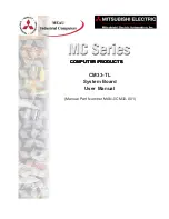
5.3.1 Installation Menu

SiS Bus Master PCI IDE Driver: Installs BUS/IDE support driver.

SiS AGP Driver: Installs graphical support driver.

C-Media Audio Driver and Application: Installs the C-Media chipset
audio support driver and software.

SiS PCI LAN Driver: Installs the fast ethernet network controller driver.

USB 2.0 Driver: Installs the latest USB 2.0 system driver.

ASUS PC Probe Vx.xx: Installs a smart utility to monitor your computer’s
fan, temperature, and voltages.

Install ASUS Update Vx.xx: Instals a program that can help you update
BIOS or download a BIOS image file.

Microsoft DirectX Driver: Installs basic drivers to enable compatibility
with audio and other special functions.

PC-Cillin 2002: Installs the PC-cillin virus protection software. View  online
help for more information.

ADOBE Acrobat Reader: Installs the Adobe Acrobat Reader software
necessary to view user’s manuals saved in PDF format. Updated or other
language versions of this motherboard's manual is available in PDF format
at any of our web sites.

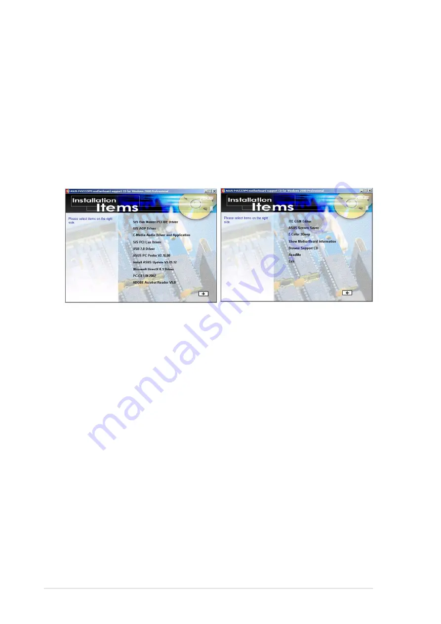
(CLICK THE ARROW ON THE LOWER-RIGHT CORNER)

Summary of Contents for P4S533-VM

Page 1: ...Motherboard P4S533 VM User Manual ...

Page 2: ... the period of the manual revision number Manual updates are represented by the third digit in the manual revision number For previous or updated manuals BIOS drivers or product release information contact ASUS at http www asus com or through any of the means indicated on the following page ASUS PROVIDES THIS MANUAL AS IS WITHOUT WARRANTY OF ANY KIND EITHER EXPRESS OR IMPLIED INCLUDING BUT NOT LIM...

Page 3: ...on BIOS beep codes Chapter 4 BIOS setup How to change system settings using onboard BIOS firmware Detailed descriptions of the BIOS parameters are supplied Chapter 5 Software support A summary of contents on the motherboard support CD ROM Appendix and Glossary Optional components and technical definitions Index Conventions used in this guide To make sure that you perform set up tasks properly take...

Page 4: ...board installation 7 2 1 Motherboard installation 7 2 1 1 Placement direction 7 2 1 2 Screw holes 7 2 2 Motherboard layout 8 2 2 1 Layout contents 9 2 3 Before you proceed 10 2 4 Central Processing Unit CPU 11 2 4 1 Overview 11 2 4 2 Installing the CPU 12 2 4 3 Installing the heatsink and fan 14 2 4 4 Connecting the CPU fan cable 16 2 5 System memory 17 2 5 1 Overview 17 2 5 2 Memory configuration...

Page 5: ... 4 3 Main menu 50 4 3 1 Primary Secondary Master Slave 51 4 3 2 Keyboard Features 55 4 4 Advanced Menu 57 4 4 1 Chip Configuration 59 4 4 2 I O Device Configuration 62 4 4 3 PCI Configuration 64 4 5 Power Menu 67 4 5 1 Power Up Control 69 4 5 2 Hardware Monitor 71 4 6 Boot Menu 72 4 7 Exit Menu 74 Chapter 5 Software support 77 5 1 Install an operating system 77 5 2 Support CD information 77 5 3 P4...

Page 6: ...rcuit Make sure that your power supply is set to the voltage available in your area If the power supply is broken contact a qualified service technician or your retailer Operational safety Before installing the motherboard and adding new devices carefully read all the manuals that came with the package Before use ensure all cables are correctly connected and the power cables arenotdamaged Ifyoudet...

Page 7: ... cause harmful interference to radio or television reception which can be determined by turning the equipment off and on the user is encouraged to try to correct the interference by one or more of the following measures Reorient or relocate the receiving antenna Increase the separation between the equipment and receiver Connect the equipment to an outlet on a circuit different from that to which t...

Page 8: ...TIONAL America Address 6737 Mowry Avenue Mowry Business Center Building 2 Newark CA 94560 USA General Fax 1 510 608 4555 General Email tmd1 asus com Technical Support Support Fax 1 510 608 4555 General Support 1 502 995 0883 Notebook Support 1 877 918 ASUS 2787 Web Site www asus com Support Email tsd asus com ASUS COMPUTER GmbH Europe Address Harkortstr 25 40880 Ratingen BRD Germany General Fax 49...

Page 9: ...Chapter 1 Product introduction ...

Page 10: ...ASUS P4S533 E motherboard ...

Page 11: ... of system memory of PC 2700 2100 1600 DDR High resolution graphics via an AGP 4X slot Digital Audio Interface for 3D sound Realtek LAN Controller onboard Two USB ports plus two headers for four more Before installing the motherboard check the items in your package 1 1 Package contents Check your P4S533 VM package for the following items ASUS P4S533 VM motherboard micro ATX 24 4 cm x 20 9 cm ASUS ...

Page 12: ... DDR DRAM the newest memory standard with the highest bandwidth and lowest latency currently available This new memory technology increases performance by executing two actions per clock cycle resulting in data transfer rates of up to 2 7 GB s for 166MHz DDR SDRAM and 2 1GB s for 133MHz DDR SDRAM UltraDMA133 Support Comes with an onboard PCI Bus Master IDE controller with two connectors that suppo...

Page 13: ...oring CPU temperature is monitored by the ASUS ASIC through the CPU s internal thermal diode to prevent overheating and damage All system fans are monitored for RPM and failure System voltage levels are monitored to ensure stable voltage to critical motherboard components Auto Fan Off The system fans powers off automatically even in sleep mode ACPI Ready Advanced Configuration Power Interface ACPI...

Page 14: ...rt COM1 35 USB Connectors Port 1 2 36 PS 2 Mouse Connector green 27 PS 2 Keyboard Connector purple 37 Hardware Monitoring System Voltage Monitor integrated in ASUS ASIC 10 Special Feature Onboard LED 13 Network Feature Realtek 100 10 Mbps LAN PHY 26 RJ45 Connector Optional 28 Audio Features on audio models only Audio Controller Chipset 22 SPDIF out Connector 8 Front Panel Audio Header 21 Audio Con...

Page 15: ...ASUS P4S533 VM motherboard user guide 5 1 4 1 Component Locations 2 3 4 5 12 16 20 19 1 18 13 21 26 15 14 9 1110 17 24 6 8 7 25 22 23 27 28 29 30 31 32 33 35 37 36 34 ...

Page 16: ......

Page 17: ...Chapter 2 Hardware information ...

Page 18: ...ASUS P4S533 VM motherboard ...

Page 19: ... the motherboard 2 1 1 Placement direction When installing the motherboard make sure that you place it into the chassis in the correct orientation The edge with external ports goes to the rear part of the chassis Refer to the image below 2 1 2 Screw holes Place six 6 screws into the holes indicated by circles to secure the motherboard to the chassis Make sure to unplug the power cord before instal...

Page 20: ... P4S533 VM SMARTCON1 FP_AUDIO1 MODEM ITE 8707F Super I O 2Mbit Flash BIOS PCI Slot 1 ATX Power Connector SEC_IDE1 Bottom USB1 USB2 Top RJ 45 DDR DIMM2 64 72 bit 184 pin module 2 3 DDR DIMM1 64 72 bit 184 pin module 0 1 Accelerated Graphics Port AGP USBPWR_12 SiS962L MuTLOL Media I 0 SPDIF_OUT1 ATX12V1 Audio Codec RTL 8201 ASUS Mozart SIRQ1 CHA_FAN1 CLRTC1 20 9cm 8 2in 24 4cm 9 6in Socket 478 COM1 ...

Page 21: ... p 31 Audio Connectors Three 1 8 jacks 8 VGA p 32 Monitor Output Connector 15 pin 9 RJ45 p 32 Fast Ethernet Port Connector 4 pin female 10 IDELED p 32 IDE Activity LED 2 pin 11 PRIMARY SEC IDE p 33 IDE Connectors Two 40 1 pin 12 FLOPPY p 34 Floppy Disk Drive Connector 34 1 pin 13 CHAS CPUFAN1 p 34 Chassis and CPU Fan Connectors Two 3 pin 14 ATXPWR p 35 ATX Power Supply Connector 20 pin 15 USB34 56...

Page 22: ...ct such as the power supply case before handling components to avoid damaging them due to static electricity 3 Hold components by the edges and do not to touch the ICs on them 4 Whenever you uninstall any component place it on a grounded antistatic pad or in the bag that came with the component 5 Before you install or remove any component ensure that the ATX power supply is switched off or the pow...

Page 23: ...o architecture The Intel NetBurst micro architecture features the hyper pipelined technology rapid execution engine 400MHz system bus and execution trace cache Together these attributes improve system performance by allowing higher processor frequencies faster execution of integer instructions and a data transfer rate of 3 2GB s Note in the illustration that the CPU has a gold triangular mark on o...

Page 24: ... to install a CPU 1 Locate the 478 pin ZIF socket on the motherboard 2 Unlock the socket by pressing the lever sideways then lift it up to a 90 100 angle Make sure that the socket lever is lifted up to 90 100 angle otherwise the CPU does not fit in completely Socket Lever 90 100 ...

Page 25: ...the CPU into the socket until it fits in place The CPU fits only in one correct orientation DO NOT force the CPU into the socket to prevent bending the pins and damaging the CPU 5 When the CPU is in place press it firmly on the socket while you push down the socket lever to secure the CPU The lever clicks on the side tab to indicate that it is locked Gold Mark ...

Page 26: ...install the CPU heatsink and fan 1 Place the heatsink on top of the installed CPU making sure that the heatsink fits properly on the retention module base When you buy a boxed Intel Pentium 4 478 Northwood Processor the package includes the heatsink fan and retention mechanism In case you buy a CPU separately make sure that you use only Intel certified heatsink and fan Your boxed Intel Pentium 4 4...

Page 27: ... to the holes on each corner of the module base Keep the retention locks lifted upward while fitting the retention mechanism to the module base Make sure that the fan and retention mechanism assembly perfectly fits the heatsink and module base otherwise you cannot snap the hooks into the holes Retention Hole Retention Hook Snapped to the Retention Hole Retention Lock ...

Page 28: ...o the connector on the motherboard labeled CPUFAN1 3 Push down the locks on the retention mechanism to secure the heatsink and fan to the module base When secure the retention locks should point to opposite directions CPU Fan Connector CPUFAN1 Don t forget to connect the CPU fan connector Hardware monitoring errors may occur if you fail to plug this connector ...

Page 29: ...C133 memory known as Single Data Rate SDR SDRAM DDR memory however has the ability to perform two data operations in one clock cycle thus providing twice the throughput of SDR memory P4S533 VM P4S533 VM 184 Pin DDR DIMM Sockets 80 Pins 104 Pins A DDR DIMM has the same physical dimensions as an SDR DIMM but it has a 184 pin footprint compared to the 168 pin of the SDR DIMM Also a DDR DIMM is single...

Page 30: ...nya NT5DS16M8AT 6 PC2700 256MB Samsung K4H280838D TCB3 PC2700 128MB Samsung K4H280838D TCB3 PC2700 256MB Micron MT8VDDT1664AG 335B1 PC2700 128MB Micron MT16VDDT3264AG 335B1 PC2700 256MB KINGMAX MPMA82D 68KX3 PC2700 128MB KINGMAX MPM62D 68KX3 PC2700 256MB DDR333 DIMM Qualified Vendor List The following table lists the DDR333 memory modules that have been tested and qualified for use with this mothe...

Page 31: ...DIMM Make sure to unplug the power supply before adding or removing DIMMs or other system components Failure to do so may cause severe damage to both the motherboard and the components Follow these steps to install a DIMM 1 Unlock a DIMM socket by pressing the retaining clips outward 2 Align a DIMM on the socket such that the notch on the DIMM matches the break on the socket Unlocked Retaining Cli...

Page 32: ...se steps to remove a DIMM 1 Simultaneously press the retaining clips outward to unlock the DIMM Support the DIMM lightly with your fingers when pressing the retaining clips The DIMM might get damaged when it flips out with extra force 2 Remove the DIMM from the socket ...

Page 33: ...umentation that came with it and make the necessary hardware settings for the card 2 Remove the system unit cover if your motherboard is already installed in a chassis 3 Remove the bracket opposite the slot that you intend to use Keep the screw for later use 4 Align the card connector with the slot and press firmly until the card is completely seated on the slot 5 Secure the card to the chassis wi...

Page 34: ...le for ISA or PCI devices IRQ assignments for this motherboard A B C D E F G H PCI slot 1 used PCI slot 2 shared PCI slot 3 used Onboard USB HC0 used Onboard USB HC1 used Onboard USB HC2 used Onboard USB HC3 used AGP shared Onboard audio shared Onboard LAN shared Onboard VGA shared When using PCI cards on shared slots ensure that the drivers support Share IRQ or that the cards do not need IRQ assi...

Page 35: ...ly with PCI specifications The following figure shows a LAN card installed on a PCI slot 2 6 4 AGP slot This motherboard has an Accelerated Graphics Port AGP slot that supports any AGP 4X 2X cards P4S533 VM P4S533 VM Accelerated Graphics Port AGP CAUTION To avoid damaging your AGP AGP Pro graphics card your computer s power supply should be unplugged before inserting your graphics card into the sl...

Page 36: ...cies only to the recommended settings Frequencies other than the recommended CPU bus frequencies are not guaranteed to be stable Overclocking the processor is not recommended as it may result in a slower speed 2 7 Jumpers The jumpers on the motherboard allow you to change some feature settings to suit your customized system configuration Before changing any FSJ or jumper setting make sure to read ...

Page 37: ...s not met the system does not power up The total current consumed must NOT exceed the power supply capability 5VSB whether under normal condition or in sleep mode Also note that ONLY USB 5VSB can support S3 resume function P4S533 VM P4S533 VM USB Device Wake Up USBPWR_12 5VSB 3 2 5V Default 1 2 5V Default 1 2 5VSB 3 2 USBPWR_56 USBPWR_34 Setting 5V default 5VSB USBPWR_12 1 2 2 3 USBPWR_34 1 2 2 3 ...

Page 38: ... shorted jumper caps on to route the signal from the audio controller to the rear panel Line Out jack to make it available for audio out devices like speakers or headphones If you connect the Intel Front Panel audio cable to the FP_Audio connector see page 38 for the location remove the caps from these jumpers to allow automatic switching of audio signals between the rear panel Line Out jack and t...

Page 39: ... erasing the CMOS RTC RAM data The RAM data in CMOS that include system setup information such as system passwords is powered by the onboard button cell battery To erase the RTC RAM 1 Turn OFF the computer and unplug the power cord 2 Remove the motherboard battery 3 Short the solder points using a delicate metal implement like a paper clip 4 Replace the battery 5 Plug the power cord and turn ON th...

Page 40: ...28 Chapter 2 Hardware information ...

Page 41: ... available to expansion cards See PS 2 Mouse Function Control in 4 4 Advanced Menu 2 PS 2 Keyboard Port Purple 6 pin PS2KBMS This connection is for a standard keyboard using an PS 2 plug mini DIN This connector does not allow standard AT size large DIN keyboard plugs You may use a DIN to mini DIN adapter on standardAT keyboards PS 2 Mouse 6 pin female WARNING Some pins are used for connectors or p...

Page 42: ... or other serial devices An onboard header supports a serial bracket To enable these ports see Onboard Serial Port 1 in 4 4 2 I O Device Configuration for the settings 4 Parallel Port Burgundy 25 pin PRINTER You can enable the parallel port and choose the IRQ through Onboard Parallel Port see 4 4 2 I O Device Configuration Universal Serial Bus USB COM 1 Serial Port 9 pin male Parallel Printer Port...

Page 43: ...udio sources The Mic pink connects a microphone NOTE The functions of the audio connectors Line Out Line In and Mic change when the 6 channel audio feature is enabled Refer to Chapter 5 SOFTWARE SETUP Game MIDI 15 pin female 6 Game MIDI Ports Gold 15 pin GAME_AUDIO optional This connector supports a joystick or a game pad for playing games and MIDI devices for playing or editing audio files P4S533...

Page 44: ...ty LED The read or write activities of any device connected to the primary or secondary IDE connector cause this LED to light up P4S533 VM P4S533 VM IDE Activity LED TIP If the case mounted LED does not light try reversing the 2 pin plug IDE_LED1 RJ 45 9 Fast Ethernet Port Connector RJ45 optional This RJ45 connector is located on top of the USB Ports 0 1 The RJ45 supports connectivity for local ar...

Page 45: ...3 100 66 devices purchase another UltraDMA133 100 66 cable You may configure two hard disks to be both master devices with two ribbon cables one for the primary IDE connector and another for the secondary IDE connector 1 Pin 20 on each IDE connector is removed to match the covered hole on the UltraDMA cable connector This prevents incorrect orientation when you connect the cables 2 The hole near t...

Page 46: ...AN1 CPUFAN1 The two fan connectors support cooling fans of 350mA 4 2 Watts or a total of 1A 12W at 12V Orient the fans so that the heat sink fins allow air flow to go across the onboard heat sinks instead of the expansion slots The fan wiring and plug may vary depending on the fan manufacturer Connect the fan cable to the connector matching the black wire to the ground pin Do not forget to connect...

Page 47: ...at you connect the 4 pin ATX 12V power plug to provide sufficient power to the CPU Make sure that your ATX 12V power supply can provide at least 8A on the 12V lead and at least 1A on the 5 volt standby lead 5VSB The minimum recommended wattage is 230W or 300W for a fully configured system The system may become unstable and may experience difficulty powering up if the power supply is inadequate P4S...

Page 48: ...ice modem card P4S533 VM P4S533 VM Internal Audio Connectors CD1 Black AUX1 White MODEM1 Right Audio Channel Left Audio Channel Ground Ground Modem Out Ground Modem In Ground 15 USB header 2x10 1 pin USB_34 _56 If the USB port connectors on the rear panel are inadequate a USB header is available for additional USB port connectors Connect the bundled 2 port USB connector set to this header and moun...

Page 49: ...board package 18 Infrared module connector 5 1 pin IR_CON1 This connector supports an optional wireless transmitting and receiving infrared module This module mounts to a small opening on system chassis that support this feature You must also configure the UART2 Use As parameter in BIOS to set UART2 for use with IR See section 4 4 2 I O Device Configuration for details Use the five pins as shown i...

Page 50: ... Smart Card Reader that allows you to conveniently make transactions such as financial health care telephony or traveling services through a Smart Card user interface software When using this connector configure the UART2 Use As parameter in BIOS to set UART2 for use with Smart Card See section 4 4 2 I O Device Configuration for details P4S533 VM P4S533 VM Smartcard SMARTCON1 1 NC SCPWR NC RFU2 NC...

Page 51: ...user guide 39 P4S533 VM P4S533 VM SIRQ1 Connector SIRQ1 SERIRQ GND 21 Serial IRQ connector 2 pin SIRQ1 optional This connector supports the serial IRQ cable This cable is required by some PCI cards like those with PCMCIA function ...

Page 52: ...indicate receipt of messages from a fax modem The normal status for this LED is ON when there is no incoming data signal The LED blinks when data is received The system message LED feature requires an ACPI OS and driver support 25 System Management Interrupt Lead 2 pin SMI This connector permits switching to suspend mode or Green mode system activity is decreased to conserve power and system compo...

Page 53: ...Chapter 3 Powering up ...

Page 54: ...ASUS P4S533 VM motherboard ...

Page 55: ...en standards or if it has a power standby feature the monitor LED may light up or switch between orange and green after the system LED turns on The system then runs the power on tests While the tests are running the BIOS beeps or additional messages appear on the screen If you do not see anything within 30 seconds from the time you turned on the power the system may have failed a power on test Che...

Page 56: ...u can press the ATX power switch after exiting or shutting down the operating system If you use Windows 95 98 2000 XP click the Start button click Shut Down then click the OK button to shut down the computer The power supply should turn off after Windows shuts down The message You can now safely turn off your computer does not appear when shutting down with ATX power supplies ...

Page 57: ...Chapter 4 BIOS setup ...

Page 58: ...ASUS P4S533 VM motherboard ...

Page 59: ...er numbers represent a newer BIOS file 1 Type FORMAT A S at the DOS prompt to create a bootable system disk DO NOT copy AUTOEXEC BAT and CONFIG SYS to the disk 2 Type COPY D AFLASH AFLASH EXE A assuming D is your CD ROM drive to copy AFLASH EXE to the boot disk you created BIOS setup must specify Floppy as the first item in the boot sequence 4 In DOS mode type A AFLASH Enter to run AFLASH If the w...

Page 60: ...pter 4 BIOS Setup 5 Select 1 Save Current BIOS to File from the Main menu and press Enter The Save Current BIOS To File screen appears 6 Type a filename and the path for example A XXX XX XXX then press Enter ...

Page 61: ...2 then press Enter The Update BIOS Including Boot Block and ESCD screen appears 5 Type the filename of your new BIOS and the path for example A XXX XX XXX then press Enter To cancel this operation press Enter 6 When prompted to confirm the BIOS update press Y to start the update Update the BIOS only if you have problems with the motherboard and you are sure that the new BIOS revision will solve yo...

Page 62: ...ge Flashed Successfully appears 8 Follow the onscreen instructions to continue If you encounter problems while updating the new BIOS DO NOT turn off the system because this may cause boot problems Just repeat the process and if the problem persists load the original BIOS file you saved to the boot disk If the Flash Memory Writer utility is not able to successfully update a complete BIOS file the s...

Page 63: ...d record them in the CMOS RAM of the EEPROM The EEPROM on the motherboard stores the Setup utility When you start up the computer the system provides you with the opportunity to run this program Press Delete during the Power On Self Test POST to enter the Setup utility otherwise POST continues with its test routines If you wish to enter Setup after POST restart the system by pressing Ctrl Alt Dele...

Page 64: ...r The keys in the legend bar allow you to navigate through the various setup menus The following table lists the keys found in the legend bar with their corresponding functions Navigation Key s Function Description F1 or Alt H Displays the General Help screen from any where in the BIOS Setup Esc Jumps to the Exit menu or returns to the main menu from a sub menu Left or Right arrow Selects the menu...

Page 65: ...p window press Enter or Esc Sub menu Note that a right pointer symbol as shown on the left appears to the left of certain fields This pointer indicates that you can display a sub menu from this field A sub menu contains additional options for a field parameter To display a sub menu move the highlight to the field and press Enter The sub menu appears Use the legend keys to enter values and move fro...

Page 66: ...y year Valid values for month day and year are Month 1 to 12 Day 1 to 31 Year up to 2084 Use the Tab or Shift Tab keys to move between the month day and year fields Legacy Diskette A 1 44M 3 5 in Sets the type of floppy drive installed Configuration options None 360K 5 25 in 1 2M 5 25 in 720K 3 5 in 1 44M 3 5 in 2 88M 3 5 in Floppy 3 Mode Support Disabled This is required to support older Japanese...

Page 67: ...s may be because the hard disk drive is too old or too new If the hard disk was already formatted on an older system Setup may detect incorrect parameters In these cases select User Type HDD to manually enter the IDE hard disk drive parameters Refer to the next section for details Before attempting to configure a hard disk drive make sure you have the correct configuration information supplied by ...

Page 68: ...sc key to return to the Main menu When the Main menu appears the hard disk drive field displays the size for the hard disk drive that you configured User Type HDD After entering the IDE hard disk drive information into BIOS use a disk utility such as FDISK to partition and format new IDE hard disk drives This is necessary so that you can write or read data from the hard disk Make sure to set the p...

Page 69: ... This field configures the number of sectors per track Refer to the drive documentation to determine the correct value To make changes to this field set the Type field to User Type HDD and the Translation Method field to Manual CHS Capacity This field shows the drive s maximum CHS capacity as calculated by the BIOS based on the drive information you entered Maximum LBA Capacity This field shows th...

Page 70: ...rease system performance Configuration options Disabled Enabled PIO Mode 4 This option lets you set a PIO Programmed Input Output mode for the IDE device Modes 0 through 4 provide successive increase in performance Configuration options 0 1 2 3 4 Ultra DMA Mode Disabled Ultra DMA capability allows improved transfer speeds and data integrity for compatible IDE devices Set to Disabled to suppress Ul...

Page 71: ... Keyboard Auto Repeat Rate 6 Sec This controls the speed at which the system registers repeated keystrokes Options range from 6 to 30 characters per second Configuration options 6 Sec 8 Sec 10 Sec 12 Sec 15 Sec 20 Sec 24 Sec 30 Sec Keyboard Auto Repeat Delay 1 4 Sec This field sets the time interval for displaying the first and second characters Configuration options 1 4 Sec 1 2 Sec 3 4 Sec 1 Sec ...

Page 72: ...rogram allows you to specify passwords in the Main menu The passwords control access to the BIOS during system startup Passwords are not case sensitive meaning passwords typed in either uppercase or lowercase letters are accepted The BIOS Setup program allows you to specify two different passwords a Supervisor password and a User password If you did not set a Supervisor password anyone can access ...

Page 73: ...nerator which frequency to send to the system bus and PCI bus The bus frequency external frequency multiplied by the bus multiple equals the CPU speed Memory Frequency Auto This field is defaulted to function automatically and determines whether the memory clock frequency is set to be in synchronous or asynchronous mode with respect to the system frequency CPU Level 2 Cache Enabled This field is d...

Page 74: ...Q12 whether or not a PS 2 mouse is detected at startup Configuration options Enabled Auto USB Legacy Support Auto This motherboard supports Universal Serial Bus USB devices The default of Auto permits the system to detect a USB device at startup If detected the USB controller legacy mode is enabled If not detected the USB controller legacy mode is disabled When you set this field to Disabled the U...

Page 75: ...ed voltage interface and module banks Configuration options User Defined By SPD NOTE The following 4 SDRAM parameters appear only when you set the SDRAM Configuration to User Defined SDRAM CAS Latency 2 5T This item controls the latency between the SDRAM read command and the time the data actually becomes available SDRAM RAS to CAS Delay 3T This item controls the latency between the SDRAM active c...

Page 76: ...nterface only provides a peak data throughput of 266MB s even if you are using an AGP 2X 4X card When set to 2X Mode the AGP interface provides a peak data trhoughput of only 533MB s even if you are using an AGP 4X card Configuration options 1X Mode 2X Mode 4X Mode AGP Fast Write Capability Disabled Configuration options Disabled Enabled Video Memory Cache Mode UC USWC uncacheable speculative writ...

Page 77: ... that is not PCI 2 1 compliant Configuration options Disabled Enabled Onboard PCI IDE Enable Both This field allows tou to enable either the primary IDE channel or secondary IDE channel or both You can also set both channels to Disabled Configuration options Both Primary Secondary Disabled IDE Bus Master Support Enable This field enables or disables the IDE Bus Master Capability under the DOS envi...

Page 78: ...board serial connectors Serial Port 1 and Serial Port 2 must have different addresses Configuration options 3F8H IRQ4 2F8H IRQ3 3E8H IRQ4 2E8H IRQ10 Disabled UART2 Use As Disabled This field allows you to select the device on which to assign UART2 If you select IR or Smart Card Reader set an I O address for the item Onboard Serial Port 2 Configuration options COM Port IR Smart Card Reader Onboard ...

Page 79: ...ed operation in a two way mode Configuration options Normal EPP ECP ECP EPP ECP DMA Select 3 This field allows you to configure the parallel port DMA channel for the selected ECP mode This selection is available only if you select ECP or ECP EPP in Parallel Port Mode above Configuration options 1 3 Onboard Game Port 200H 207H This field sets the I O address to the game port Configuration options 2...

Page 80: ...ds may not show colors properly Setting this field to Enabled corrects this problem If you are using standard VGA cards leave this field to the default setting Disabled Configuration options Disabled Enabled PCI Latency Timer 32 Leave this field to the default setting 32 for best performance and stability Primary VGA BIOS PCI VGA Card This field allows you to select the primary graphics card Confi...

Page 81: ...s motherboard supports Universal Serial Bus USB devices Keep the default setting Enabled if you connect USB devices Select the setting Disabled if you do not wish to use the USB feature Configuration options Disabled Enabled USB 2 0 Function Enabled This motherboard supports Universal Serial Bus 2 0 USB devices Keep the default setting Enabled if you connect USB 2 0 devices Select the setting Disa...

Page 82: ...s if you install a legacy ISA card that requires a unique IRQ and you are NOT using ICU Configuration options No ICU Yes 4 4 3 2 PCI IRQ Resource Exclusion Onboard AC97 Audio Controller Auto Auto allows the BIOS to detect whether you are using any modem audio device If a modem audio device is detected the onboard modem audio controller is enabled if no modem audio device is detected the controller...

Page 83: ...When set to Max Saving system power is conserved to its greatest amount This setting automatically puts the system into suspend mode after a brief period of system inactivity Min Saving allows the least power saving as the system enters suspend mode only after a long period of inactivity Configuration options User Defined Disabled Min Saving Max Saving You should install the Advanced Power Managem...

Page 84: ...hard disk drives in the system after a period of inactivity as set in this user configurable field This feature does not affect SCSI hard drives Configuration options Disabled 1 Min 2 Min 3 Min 15 Min ACPI Suspend To RAM Disabled This field allows you to enable or disable the ACPI Suspend to RAM feature To support this feature the 5VSB of the power supply should have the capacity to provide more t...

Page 85: ...for powering up the computer when the external modem receives a call while the computer is in Soft off mode Configuration options Disabled Enabled The computer cannot receive or transmit data until the computer and applications are fully running Thus connection cannot be made on the first try Turning an external modem off and then back on while the computer is off causes an initialization string t...

Page 86: ...parameter allows you to use specific keys on the keyboard to turn on the system This feature requires an ATX power supply that provides at least 1A on the 5VSB lead Configuration options Disabled Space Bar Ctrl Esc Power Key Automatic Power Up Disabled This allows an unattended or automatic system power up You may configure your system to power up at a certain time of the day by selecting Everyday...

Page 87: ...xxRPM or N A The onboard hardware monitor automatically detects the CPU and chassis fan speeds and displays the fan speeds in revolutions per minute RPM If any of the fans is not connected to the fan connectors on the motherboard the specific field will show N A VCORE Voltage 3 3V Voltage 5V Voltage 12V Voltage The onboard hardware monitor automatically detects the voltage output through the onboa...

Page 88: ...ard Drive ATAPI CD ROM and Other Boot Device Removable Device Legacy Floppy Configuration options Disabled Legacy Floppy LS 120 ZIP ATAPIMO IDE Hard Drive This field allows you to select which IDE hard disk drive to use in the boot sequence Pressing Enter will show the product IDs of all connected IDE hard disk drives ATAPI CD ROM This field allows you to select which ATAPI CD ROM drive to use in ...

Page 89: ...s Disabled Enabled Quick Power On Self Test Enabled This field speeds up the Power On Self Test POST routine by skipping retesting a second third and fourth time Configuration options Disabled Enabled Boot Up Floppy Seek Enabled When enabled the BIOS will seek the floppy disk drive to determine whether the drive has 40 or 80 tracks Configuration options Disabled Enabled Full Screen Logo Enabled Th...

Page 90: ...f When you select this option a confirmation window appears Select Yes to save changes and exit Pressing Esc does not immediately exit this menu Select one of the options from this menu or F10 from the legend bar to exit If you attempt to exit the Setup program without saving your changes the program prompts you with a message asking if you want to save your changes before exiting Pressing Enter s...

Page 91: ...ing the values to the non volatile RAM Discard Changes This option allows you to discard the selections you made and restore the previously saved values After selecting this option a confirmation appears Select Yes to discard any changes and load the previously saved values Save Changes This option saves your selections without exiting the Setup program You can then return to other menus and make ...

Page 92: ...76 Chapter 4 BIOS Setup ...

Page 93: ...Chapter 5 Software support ...

Page 94: ...ASUS P4S533 VM motherboard ...

Page 95: ...in this chapter to install the software and drivers contained in the support CD NOTE Because motherboard settings and hardware options vary use the setup procedures presented in this chapter for general reference only Refer to your OS documentation for more information 5 2 Support CD information The support CD that came with the motherboard contains useful software and several utility drivers that...

Page 96: ...AN Driver Installs the fast ethernet network controller driver USB 2 0 Driver Installs the latest USB 2 0 system driver ASUS PC Probe Vx xx Installs a smart utility to monitor your computer s fan temperature and voltages Install ASUS Update Vx xx Instals a program that can help you update BIOS or download a BIOS image file Microsoft DirectX Driver Installs basic drivers to enable compatibility wit...

Page 97: ...h as product name BIOS version and CPU Browse Support CD Allows you to view the contents of the CD ReadMe Allows you to view the support CD file list and contact information Exit Exits the CD installation menu It is not advisable to install any software contained on the support CD which does not appear here on the setup menu The ITE GSM Editor will only appear if you have adjusted the I O Device C...

Page 98: ...l frequencies through the DMI Explorer 5 4 1 Starting ASUS PC Probe WhenASUS PC Probe starts a splash screen appears allowing you to select whether or not to show the screen the next time you open PC Probe To bypass this startup screen clear the Show up in next execution check box The PC Probe icon will appear on the taskbar s system tray indicating that ASUS PC Probe is running Clicking the icon ...

Page 99: ...hows the PC s temperature Temperature Warning threshold adjustment Move the slider up to increase the threshold level or down to decrease the threshold level Fan Monitor Shows the PC s fan rotation Voltage Monitor Shows the PC s voltages Fan Warning threshold adjustment Move the slider up to increase the threshold level or down to decrease the threshold level ...

Page 100: ...rent monitoring activity of a certain component of your PC for future reference Hard Drives Shows the used and free space of the PC s hard disk drives and the file allocation table or file system used CPU Cooling System Setup Lets you select when to enable software CPU cooling When When CPU Overheated is selected the CPU cooling system is enabled whenever the CPU temperature reaches the threshold ...

Page 101: ...I Explorer Shows information pertinent to the PC such as CPU type CPU speed and internal external frequencies and memory size Utility Lets you run programs outside of the ASUS Probe modules To run a program click Execute Program Memory Shows the PC s memory load memory usage and paging file usage ...

Page 102: ...S PC Probe senses a problem with your PC portions of the ASUS PC Probe icon changes to red the PC speaker beeps and the ASUS PC Probe monitor is displayed Right clicking the PC Probe icon will bring up a menu to open or exit ASUS PC Probe and pause or resume all system monitoring ...

Page 103: ...s AsusUpdate 2 Select an update method 3 If you selected downloading from the Internet you will need to select an Internet site Choose the site that is closest to you or clickAuto Select 4 From the FTP site select the BIOS version that you wish to download Click Next 5 Follow the instructions on the succeeding screens to complete the update process If you selected the option to update the BIOS fro...

Page 104: ...ions to match true internet source colors with the color displayed on the monitor Simply run the setup program from the start menu and follow the instructions on the various setup test screens 5 6 1 3Deep Color Tuning 2 Follow the instructions to manually adjust the brightness level of the monitor 3 Select the faintest of the three colors blue red and green 1 Select the type of monitor connected t...

Page 105: ...e tuning process is complete Click on the bottom left button to connect to the internet and follow the instructions 5 6 2 The 3Deep Control Panel Using the Windows Start button activate the 3Deep Control Panel program from the 3Deep Applications group on the Main Program menu The control panel offers access to the Color Wizard tuning program a Game Gamma setting and a Tweak slider for brightness a...

Page 106: ...unblocking Setting Up ITE GSM Editor Connect a smart card reader to the P4S533 VM refer to page 38 in Hardware Setup for the connector location Boot up the PC and enter BIOS press del to change the configuration to accept smart card hardware in the Advanced BIOS menu select the I O Device Configuration sub menu go to UART2 Function Selection and choose Smart Card Read save and exit Finish booting ...

Page 107: ... a conversion card slip the SIM chip into the conversion card and then insert it into the card reader 2 To access the phone book contained in the SIM card either click the chip icon 3 To edit data select the field and double click it or press Enter Type in the name and number Then click OK Or double click the SIM Card 5 To save data to the SIM chip click the save icon 4 The data appears in the fie...

Page 108: ...ears in front of the serial number indicated 3 Select Entry to Write into SIM Card and the program writes the selected data from the open file into the SIM card database Users can select multiple entries by pressing Ctrl and mouse selecting the data fields simultaneously Phone number entries may be comprised of 1 2 3 4 5 6 7 8 9 C or Pressing C commands the dialer to pause for three seconds before...

Page 109: ...ked 2 Disable PIN Set Up This function is used to disable the personal identification number PIN set up It is effective only when the PIN set up is enabled and the SIM chip is not blocked Users should first enter the current PIN to disable the PIN set up If the correct PIN numbers are entered the SIM chip can be reset If three consecutive attempts to enter the PIN fail the SIM chip is automaticall...

Page 110: ......

Page 111: ...Glossary ...

Page 112: ...ASUS P4S533 VM motherboard ...

Page 113: ...tem and application software This enables the system to automatically turn ON and OFF peripherals such as CD ROMs network cards hard disk drives and printers as well as consumer devices connected to the PC such as VCRs TVs phones and stereos With this technology peripherals will also be able to activate the PC For example inserting a tape into a VCR can turn on the PC which could then activate a l...

Page 114: ...ral Processing Unit The CPU sometimes called Processor actually functions as the brain of the computer It interprets and executes program commands and processes data stored in memory Currently there are socket 370 for Pentium III FC PGA and Celeron PPGA socket 7 for Pentium AMD Cyrix IBM slot 1 for Pentium II and III slot 2 for Xeon and slot A for AMD processors Device Driver A device driver is a ...

Page 115: ...the phone system Network An interconnected computer system linked by telephone wires or other means OnNow The OnNow design initiative is a comprehensive system wide approach to system and device power control OnNow is a term for PC that is always ON but appears OFF and responds immediately to user or other requests The OnNow design initiative involves changes that will occur in the Microsoft Windo...

Page 116: ...ay from the CPU control internal registers in the memory accept the request and lets the CPU do something else while the data requested is assembled for the next time the CPU talks to the memory SPD for SDRAM module Serial Presence Detect SPD is most like an ID detect for SDRAM module it using a EEPROM component on DIMM module for storing module configuration information inside The Serial Presence...

Page 117: ...Index ...

Page 118: ...ASUS P4S533 VM motherboard ...

Page 119: ...Beep Codes 41 Boot Device Selection 72 Boot Up NumLock Status 55 Boot Virus Detection 73 C Central Processing Unit CPU 11 External Frequency 25 installation 12 Speed 57 Chip Configuration 59 Clear RTC RAM 28 Connectors chassis alarm 34 digital audio 37 fan 34 floppy disk 34 Floppy Disk Drive 9 Game MIDI 9 31 HDD LED 29 infrared module 37 internal audio 36 Parallel Port 30 power supply 35 primary s...

Page 120: ...E GSM Editor 88 J JumperFree Mode 24 Jumpers Clear RTC RAM 28 CPU external frequency 25 JumperFree mode 24 USB device wake up 26 K Keyboard Auto Repeat Delay 55 Auto Repeat Rate 55 Connector 29 Features 55 L Legacy Diskette 50 LiveUpdate 86 Using 86 M Motherboard IRQ Table 22 layout 8 9 placement 7 screws 7 Mouse Connector 29 Multi Sector Transfers 53 O Operating system installation 77 P Parallel ...

Page 121: ...S to CAS Delay 59 Serial Ports 62 Connectors 30 slots AGP 23 PCI 23 Smart Card Reader 38 Smart Manager 88 SMART Monitoring 54 Sony Philips Digital Interface S PDIF 3 Support CD 77 Welcome screen 77 Suspend Mode 68 System Date 50 System memory configurations 17 System Time 50 U UART2 64 Ultra DMA Mode 54 Universal Serial Bus USB 30 Ports 30 USB Legacy Support 59 Using 3Deep Color Tuner 86 ASUS Upda...

Page 122: ...100 Index ...

Reviews: