Asus Motherboard NCL-D User Manual Download Page 160

6 - 4

6 - 4

6 - 4

6 - 4

6 - 4

C h a p t e r   6 :   D r i v e r   i n s t a l l a t i o n

C h a p t e r   6 :   D r i v e r   i n s t a l l a t i o n

C h a p t e r   6 :   D r i v e r   i n s t a l l a t i o n

C h a p t e r   6 :   D r i v e r   i n s t a l l a t i o n

C h a p t e r   6 :   D r i v e r   i n s t a l l a t i o n

5.

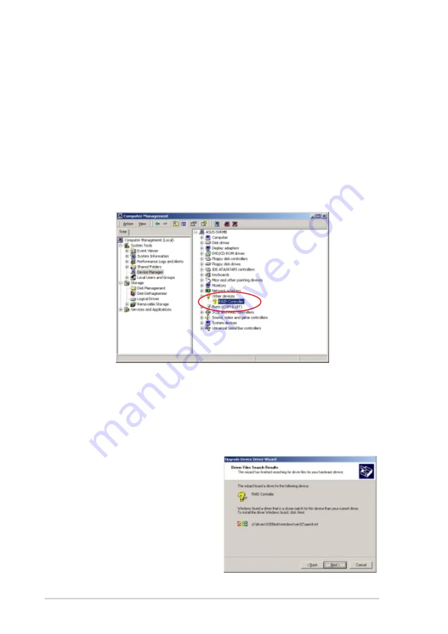
Right-click the R A I D   c o n t r o l l e r  

R A I D   c o n t r o l l e r  

R A I D   c o n t r o l l e r  

R A I D   c o n t r o l l e r  

R A I D   c o n t r o l l e r  item, then select P r o p e r t i e s

P r o p e r t i e s

P r o p e r t i e s

P r o p e r t i e s

P r o p e r t i e s.

6.

Click the D r i v e r  

D r i v e r  

D r i v e r  

D r i v e r  

D r i v e r  tab, then click the U p d a t e   D r i v e r  

U p d a t e   D r i v e r  

U p d a t e   D r i v e r  

U p d a t e   D r i v e r  

U p d a t e   D r i v e r  button.

7.

The U p g r a d e   D e v i c e   D r i v e r   W i z a r d

U p g r a d e   D e v i c e   D r i v e r   W i z a r d

U p g r a d e   D e v i c e   D r i v e r   W i z a r d

U p g r a d e   D e v i c e   D r i v e r   W i z a r d

U p g r a d e   D e v i c e   D r i v e r   W i z a r d window appears. Click N e x t

N e x t

N e x t

N e x t

N e x t.

8.

Insert the RAID driver disk you created earlier to the floppy disk drive.

9.

Select the option “Search for a suitable driver for my device

S e a r c h   f o r   a   s u i t a b l e   d r i v e r   f o r   m y   d e v i c e

S e a r c h   f o r   a   s u i t a b l e   d r i v e r   f o r   m y   d e v i c e

S e a r c h   f o r   a   s u i t a b l e   d r i v e r   f o r   m y   d e v i c e

S e a r c h   f o r   a   s u i t a b l e   d r i v e r   f o r   m y   d e v i c e

( r e c o m m e n d e d )

( r e c o m m e n d e d )

( r e c o m m e n d e d )

( r e c o m m e n d e d )

( r e c o m m e n d e d ), then click N e x t

N e x t

N e x t

N e x t

N e x t.

10. The wizard searches the RAID

controller drivers. When
found, click N e x t  

N e x t  

N e x t  

N e x t  

N e x t   to  install

the drivers.

11. Click F i n i s h  

F i n i s h  

F i n i s h  

F i n i s h  

F i n i s h  after the driver

installation is done.

T o   a n   e x i s t i n g   W i n d o w s

T o   a n   e x i s t i n g   W i n d o w s

T o   a n   e x i s t i n g   W i n d o w s

T o   a n   e x i s t i n g   W i n d o w s

T o   a n   e x i s t i n g   W i n d o w s

®

®

®

®

®

  2 0 0 0 / 2 0 0 3   S e r v e r   O S

  2 0 0 0 / 2 0 0 3   S e r v e r   O S

  2 0 0 0 / 2 0 0 3   S e r v e r   O S

  2 0 0 0 / 2 0 0 3   S e r v e r   O S

  2 0 0 0 / 2 0 0 3   S e r v e r   O S

To install the RAID controller driver on an existing Windows

®

 2000/

2003 Server OS:

1.

Restart the computer, then log in with A d m i n i s t r a t o r

A d m i n i s t r a t o r

A d m i n i s t r a t o r

A d m i n i s t r a t o r

A d m i n i s t r a t o r privileges.

2.

Windows

®

 automatically detects the RAID controller and displays a

N e w   H a r d w a r e   F o u n d

N e w   H a r d w a r e   F o u n d

N e w   H a r d w a r e   F o u n d

N e w   H a r d w a r e   F o u n d

N e w   H a r d w a r e   F o u n d window. Click C a n c e l

C a n c e l

C a n c e l

C a n c e l

C a n c e l.

3.

Right-click the M y   C o m p u t e r  

M y   C o m p u t e r  

M y   C o m p u t e r  

M y   C o m p u t e r  

M y   C o m p u t e r  icon on the Windows

®

 desktop , then

select P r o p e r t i e s  

P r o p e r t i e s  

P r o p e r t i e s  

P r o p e r t i e s  

P r o p e r t i e s  from the menu.

4.

Click the H a r d w a r e  

H a r d w a r e  

H a r d w a r e  

H a r d w a r e  

H a r d w a r e  tab, then click the D e v i c e   M a n a g e r  

D e v i c e   M a n a g e r  

D e v i c e   M a n a g e r  

D e v i c e   M a n a g e r  

D e v i c e   M a n a g e r  button to

display the list of devices installed in the system.

Summary of Contents for Motherboard NCL-D

Page 1: ...Motherboard NCL DE Series NCL DE SCSI NCL DE SCSI NCL DE SCSI NCL DE SCSI NCL DE SCSI NCL DE 1U NCL DE 1U NCL DE 1U NCL DE 1U NCL DE 1U ...

Page 2: ...he product is defaced or missing ASUS PROVIDES THIS MANUAL AS IS WITHOUT WARRANTY OF ANY KIND EITHER EXPRESS OR IMPLIED INCLUDING BUT NOT LIMITED TO THE IMPLIED WARRANTIES OR CONDITIONS OF MERCHANTABILITY OR FITNESS FOR A PARTICULAR PURPOSE IN NO EVENT SHALL ASUS ITS DIRECTORS OFFICERS EMPLOYEES OR AGENTS BE LIABLE FOR ANY INDIRECT SPECIAL INCIDENTAL OR CONSEQUENTIAL DAMAGES INCLUDING DAMAGES FOR ...

Page 3: ...dware information 2 1 Before you proceed 2 1 2 2 Motherboard overview 2 2 2 2 1 Placement direction 2 2 2 2 2 Screw holes 2 2 2 2 3 Support kits for the motherboard 2 3 2 2 4 Motherboard layouts 2 6 2 2 5 Layout contents 2 8 2 3 Central Processing Unit CPU 2 10 2 3 1 Installing the CPU 2 10 2 3 2 Installing the CPU heatsink and fan 2 12 2 4 System memory 2 14 2 4 1 Overview 2 14 2 4 2 Memory confi...

Page 4: ...OS utility 4 2 4 1 3 ASUS CrashFree BIOS 2 utility 4 5 4 1 4 ASUS Update utility 4 7 4 2 BIOS setup program 4 10 4 2 1 BIOS menu screen 4 11 4 2 2 Menu bar 4 11 4 2 3 Navigation keys 4 11 4 2 4 Menu items 4 12 4 2 5 Sub menu items 4 12 4 2 6 Configuration fields 4 12 4 2 7 Pop up window 4 12 4 2 8 Scroll bar 4 12 4 2 9 General help 4 12 4 3 Main menu 4 13 4 3 1 System Date 4 13 4 3 2 System Time 4...

Page 5: ...5 2 3 Initializing the logical drives 5 14 5 2 4 Rebuilding failed drives 5 19 5 2 5 Checking the drives for data consistency 5 21 5 2 6 Deleting a RAID configuration 5 24 5 2 7 Selecting the boot drive from a RAID set 5 25 5 2 8 Enabling the WriteCache 5 26 5 3 Global Array Manager 5 26 5 4 Adaptec SCSISelect TM Utility NCL DE SCSI model only 5 27 5 4 1 Configuring the SCSI controller 5 28 5 4 2 ...

Page 6: ... Hat Enterprise ver 3 0 6 11 6 3 VGA driver installation 6 13 6 3 1 Windows 2000 Server 6 13 6 3 2 Windows 2003 Server 6 14 6 3 3 Red Hat Enterprise ver 3 0 6 14 6 4 Management applications and utilities installation 6 15 6 4 1 Running the support CD 6 15 6 4 2 Drivers menu 6 15 6 4 3 Management Software menu 6 16 6 4 4 Utilities menu 6 16 6 4 5 Contact information 6 16 Appendix Block diagrams App...

Page 7: ...e user is encouraged to try to correct the interference by one or more of the following measures Reorient or relocate the receiving antenna Increase the separation between the equipment and receiver Connect the equipment to an outlet on a circuit different from that to which the receiver is connected Consult the dealer or an experienced radio TV technician for help Canadian Department of Communica...

Page 8: ... correct voltage in your area If you are not sure about the voltage of the electrical outlet you are using contact your local power company If the power supply is broken do not try to fix it by yourself Contact a qualified service technician or your retailer Operation safety Operation safety Operation safety Operation safety Operation safety Before installing the motherboard and adding devices on ...

Page 9: ...e also provided Chapter 5 RAID configuration Chapter 5 RAID configuration Chapter 5 RAID configuration Chapter 5 RAID configuration Chapter 5 RAID configuration This chapter provides instructions for setting up creating and configuring RAID sets using the available utilities Chapter 6 Driver installation Chapter 6 Driver installation Chapter 6 Driver installation Chapter 6 Driver installation Chap...

Page 10: ... or Return key Key1 Key2 Key3 If you must press two or more keys simultaneously the key names are linked with a plus sign Example Ctrl Alt D Command Means that you must type the command exactly as shown then supply the required item or value enclosed in brackets Example At the DOS prompt type the command line format A S DANGER WARNING DANGER WARNING DANGER WARNING DANGER WARNING DANGER WARNING Inf...

Page 11: ... GB system memory NCL DE SCSI model only 1 x PCI Express x16 slot 164P x8 link PCI Express 1 0a 1 x PCI Express x8 slot 98P x4 link PCI Express 1 0a 3 x PCI X 133 MHz 64 bit slots 184P PCI X 1 0 1 x PCI 33 MHz 32 bit 5V slot PCI 2 3 1 x Zero Channel RAID ZCR slot for Adaptec AIC 7902 ZCR board NCL DE 1U model only 1 x PCI Express x16 slot 164P x8 link PCI Express 1 0a 1 x mini PCI socket for ASUS ...

Page 12: ...hFree BIOS 2 ASUS MyLogo2 AMI BIOS 8 Mb FWH Green PnP DMI2 0a ACPI 2 0a SMBIOS 2 3 WfM2 0 1 x PS 2 keyboard port purple 1 x PS 2 mouse port green 2 x USB 2 0 ports 1 x Serial port 1 x VGA port 2 x LAN RJ 45 ports 1 x Parallel port NCL DE SCSI model only 1 x Floppy disk drive connector 2 x IDE connectors 2 x Serial ATA connectors 1 x Hard disk activity LED connector CPU chassis and power fan connec...

Page 13: ...1 Product introduction This chapter describes the motherboard features and the new technologies it supports ...

Page 14: ...ASUS NCL DE Series ASUS NCL DE Series ASUS NCL DE Series ASUS NCL DE Series ASUS NCL DE Series Chapter summary 1 1 1 Welcome 1 1 1 2 Package contents 1 1 1 3 Special features 1 2 ...

Page 15: ...package with the list below 1 2 Package contents Check your motherboard package for the following items Motherboard Motherboard Motherboard Motherboard Motherboard ASUS NCL DE Series motherboard Cables Cables Cables Cables Cables 2 x Serial ATA signal cables 1 x Serial ATA power cable dual plug 2 x SCSI Ultra320 cable NCL DE SCSI model only NCL DE SCSI model only NCL DE SCSI model only NCL DE SCSI...

Page 16: ...ssor dual channel DDR2 400 memory and PCI Express interfaces The ICH is a new generation server class I O controller hub that provides the interface for PCI 2 3 DDR2 memory support DDR2 memory support DDR2 memory support DDR2 memory support DDR2 memory support The motherboard supports DDR2 memory which features data transfer rates of 400 MHz to meet the higher bandwidth requirements of the latest ...

Page 17: ...chnology Serial ATA technology Serial ATA technology Serial ATA technology Serial ATA technology The motherboard supports the Serial ATA technology through the Serial ATA interfaces controlled by the Intel ICH5R The SATA specification allows for thinner more flexible cables with lower pin count reduced voltage requirement and up to 150 MB s data transfer rate See page 2 28 for details USB 2 0 tech...

Page 18: ...from the support CD in case when the BIOS codes and data are corrupted This protection eliminates the need to buy a replacement ROM chip See page 4 5 for details ASUS Smart Fan technology ASUS Smart Fan technology ASUS Smart Fan technology ASUS Smart Fan technology ASUS Smart Fan technology The ASUS Smart Fan technology smartly adjusts the fan speeds according to the system loading to ensure quiet...

Page 19: ... Hardware information This chapter lists the hardware setup procedures that you have to perform when installing system components It includes description of the jumpers and connectors on the motherboard ...

Page 20: ...CL DE Series ASUS NCL DE Series ASUS NCL DE Series Chapter summary 2 2 1 Before you proceed 2 1 2 2 Motherboard overview 2 2 2 3 Central Processing Unit CPU 2 10 2 4 System memory 2 14 2 5 Expansion slots 2 17 2 6 Jumpers 2 21 2 7 Connectors 2 26 ...

Page 21: ...m due to static electricity Hold components by the edges to avoid touching the ICs on them Whenever you uninstall any component place it on a grounded antistatic pad or in the bag that came with the component Before you install or remove any component ensure Before you install or remove any component ensure Before you install or remove any component ensure Before you install or remove any componen...

Page 22: ...rect orientation The edge with external ports goes to the rear part of the chassis as indicated in the image below 2 2 2 2 2 2 2 2 2 2 2 2 2 2 2 Screw holes Screw holes Screw holes Screw holes Screw holes Place nine 9 screws into the holes indicated by circles to secure the motherboard to the chassis Do not overtighten the screws Doing so can damage the motherboard Make sure to unplug the chassis ...

Page 23: ... install the CEK spring 1 Locate the CPU heatsink holes on the motherboard 2 Position the CEK spring underneath the motherboard then match the CEK spring hooks to the CPU1 heatsink holes Heatsink hole Heatsink hole Heatsink hole Heatsink hole Heatsink hole Socket for CPU1 Socket for CPU1 Socket for CPU1 Socket for CPU1 Socket for CPU1 Socket for CPU2 Socket for CPU2 Socket for CPU2 Socket for CPU2...

Page 24: ... to the lower CPU heatsink holes until they snap in place 5 If you installed a second CPU repeat steps 2 to 4 to install the CEK spring to the CPU2 heatsink holes The CEK springs appear as shown when installed CEK spring screw hole CEK spring screw hole CEK spring screw hole CEK spring screw hole CEK spring screw hole 3 Press the upper spring hooks inward then insert to the upper CPU heatsink hole...

Page 25: ... CEK spring screw holes otherwise you can not install the CPU heatsinks properly 7 Install the motherboard with the external I O ports toward the chassis rear panel The CPU sockets should be right on top of their respective standoffs Standoffs for CPU1 Standoffs for CPU1 Standoffs for CPU1 Standoffs for CPU1 Standoffs for CPU1 Standoffs for CPU2 Standoffs for CPU2 Standoffs for CPU2 Standoffs for ...

Page 26: ...um Cell CMOS Power PANEL1 FRNT_FAN1 mPGA 604 PS 2 T Mouse B Keyboard USB1 USB2 COM1 PARALLEL PORT VGA1 RJ 45 LAN 1 RJ 45 LAN 2 DDR DIMM_B1 64 72 bit 240 pin module DDR DIMM_A2 64 72 bit 240 pin module DDR DIMM_B2 64 72 bit 240 pin module DDR DIMM_A3 64 72 bit 240 pin module DDR DIMM_B3 64 72 bit 240 pin module DDR DIMM_A4 64 72 bit 240 pin module DDR DIMM_B4 64 72 bit 240 pin module mPGA 604 33cm ...

Page 27: ...ouse B Keyboard USB1 USB2 RJ 45 LAN 1 RJ 45 LAN 2 DDR DIMM_B1 64 72 bit 240 pin module DDR DIMM_A2 64 72 bit 240 pin module DDR DIMM_B2 64 72 bit 240 pin module DDR DIMM_A3 64 72 bit 240 pin module DDR DIMM_B3 64 72 bit 240 pin module DDR DIMM_A4 64 72 bit 240 pin module DDR DIMM_B4 64 72 bit 240 pin module mPGA 604 33cm 13in 30 5cm 12in PRI_IDE FRNT_FAN2 SATA2 ATX12V1 CPU_FAN1 FM_CPU1 Intel ICH5R...

Page 28: ...a g e P a g e P a g e P a g e 1 Clear RTC RAM CLRTC1 2 21 2 CPU fan pin selection 3 pin FM_CPU1 FM_CPU2 2 22 3 USB device wake up 3 pin USBPW12 USBPW34 2 22 4 Keyboard power 3 pin KBPWR1 2 23 5 VGA controller setting 3 pin VGA_EN1 2 23 6 Gigabit LAN controller setting 3 pin LAN1_EN1 2 24 7 Gigabit LAN controller setting 3 pin LAN2_EN1 2 24 8 SCSI controller setting 3 pin SCSI_EN1 2 25 9 Force BIOS...

Page 29: ... pin SATA1 SATA2 2 28 4 Ultra320 SCSI connectors two 68 pin SCSIA1 SCSIB1 2 29 5 Hard disk activity LED connector 4 pin HDLED1 2 29 6 USB connector 10 1 pin USB34 2 30 7 Serial port connector 10 1 pin COM2 2 31 8 CPU and system fan connectors 3 pin CPU_FAN1 2 REAR_FAN1 2 FRNT_FAN1 2 2 31 9 BMC connector 16 pin BMCCONN1 2 32 10 Backplane SMBus connector 6 1 pin BPSMB1 2 32 11 Power supply SMBus con...

Page 30: ...he motherboard comes with surface mount 604 pin Zero Insertion Force ZIF sockets The sockets are designed for the Intel Xeon processor in the 604 pin package with 1 MB L2 cache The new generation Xeon processor supports 800 MHz system bus and Extended Memory 64 bit Technology EM64T If installing only one CPU use the socket CPU1 2 Flip up the socket lever and push it all the way to the other side M...

Page 31: ...r clicks on the side tab to indicate that it is locked 6 Apply the thermal interface material thermal grease to the top of the CPU This thermal grease should come with the CPU package 7 Repeat steps 1 to 6 if you wish to install a second CPU The CPU fits only in one correct orientation DO NOT force the CPU into the socket to prevent bending the pins and damaging the CPU Marked corner Marked corner...

Page 32: ...the CPU heatsink and fan Make sure that you have applied the thermal grease to the top of the CPU before installing the heatsink and fan Refer to the installation manual that came with the CPU package for details on heatsink fan assembly and installation To install the CPU heatsink and fan 1 Place the heatsink on top of the installed CPU making sure that the four screws on the heatsink align with ...

Page 33: ...il to plug this connector 2 Use a Phillips screwdriver to tighten the four heatsink screws in a diagonal sequence 3 Connect the fan cable to the 4 pin connector labeled CPU_FAN1 4 Repeat steps 1 to 3 to install the other heatsink if you have installed a second CPU then connect the fan cable to the 4 pin connector labeled CPU_FAN2 The heatsinks appear as shown when installed CPU_FAN1 connector CPU_...

Page 34: ...u may install 256 MB 512 MB and 1 GB registered ECC DDR2 DIMMs into the DIMM sockets Always install DIMMs with the same CAS latency For optimum compatibility it is recommended that you obtain memory modules from the same vendor Refer to the DDR2 Qualified Vendors List at the ASUS web site Due to chipset resource allocation the system may detect less than 16 GB system memory when you installed eigh...

Page 35: ... M M A 1 S i n g l e R a n k D I M M A 1 MCH MCH MCH MCH MCH D u a l R a n k D I M M B 4 D u a l R a n k D I M M B 4 D u a l R a n k D I M M B 4 D u a l R a n k D I M M B 4 D u a l R a n k D I M M B 4 D u a l R a n k D I M M A 4 D u a l R a n k D I M M A 4 D u a l R a n k D I M M A 4 D u a l R a n k D I M M A 4 D u a l R a n k D I M M A 4 S i n g l e R a n k D I M M B 3 S i n g l e R a n k D I M M...

Page 36: ...and the DIMM is properly seated 2 4 4 2 4 4 2 4 4 2 4 4 2 4 4 Removing a DIMM Removing a DIMM Removing a DIMM Removing a DIMM Removing a DIMM Follow these steps to remove a DIMM 1 Simultaneously press the retaining clips outward to unlock the DIMM 2 Remove the DIMM from the socket A DDR2 DIMM is keyed with a notch so that it fits in only one direction Do not force a DIMM into a socket to avoid dam...

Page 37: ...ress firmly until the card is completely seated on the slot 5 Secure the card to the chassis with the screw you removed earlier 6 Replace the system cover 2 5 2 2 5 2 2 5 2 2 5 2 2 5 2 Configuring an expansion card Configuring an expansion card Configuring an expansion card Configuring an expansion card Configuring an expansion card After installing the expansion card configure the it by adjusting...

Page 38: ...nts I R Q I R Q I R Q I R Q I R Q Priority Priority Priority Priority Priority Standard Function Standard Function Standard Function Standard Function Standard Function 0 1 System Timer 1 2 Keyboard Controller 2 Re direct to IRQ 9 3 11 Communications Port COM2 4 12 Communications Port COM1 5 13 IRQ holder for PCI steering 6 14 Floppy Disk Controller 7 15 Printer Port LPT1 8 3 System CMOS Real Time...

Page 39: ... PCI X 1 0 specifications The figure shows a LAN card installed on a PCI slot 32 bit PCI slot 32 bit PCI slot 32 bit PCI slot 32 bit PCI slot 32 bit PCI slot 64 bit PCI X slot 64 bit PCI X slot 64 bit PCI X slot 64 bit PCI X slot 64 bit PCI X slot The figure shows a RAID card installed on a PCI X slot 2 5 5 2 5 5 2 5 5 2 5 5 2 5 5 ZCR socket ZCR socket ZCR socket ZCR socket ZCR socket For NCL DE S...

Page 40: ...1U models For both NCL DE SCSI and NCL DE 1U models This motherboard supports PCI Express x16 graphic cards that comply with the PCI Express specifications 2 5 7 2 5 7 2 5 7 2 5 7 2 5 7 PCI Express x8 slot PCI Express x8 slot PCI Express x8 slot PCI Express x8 slot PCI Express x8 slot For NCL DE SCSI model only For NCL DE SCSI model only For NCL DE SCSI model only For NCL DE SCSI model only For NC...

Page 41: ...TC RAM in CMOS You can clear the CMOS memory of date time and system setup parameters by erasing the CMOS RTC RAM data The onboard button cell battery powers the RAM data in CMOS which include system setup information such as system passwords To erase the RTC RAM 1 Turn OFF the computer and unplug the power cord 2 Remove the onboard battery 3 Move the jumper cap from pins 1 2 default to pins 2 3 K...

Page 42: ...h USB port otherwise the system would not power up If you are using Windows 2000 you need to install Service Pack 4 to wake up the system from S4 sleep mode The total current consumed must NOT exceed the power supply capability 5VSB whether under normal condition or in sleep mode 2 2 2 2 2 CPU fan pin selection 3 pin FM_CPU1 FM_CPU2 CPU fan pin selection 3 pin FM_CPU1 FM_CPU2 CPU fan pin selection...

Page 43: ...e default is the Space Bar This feature requires an ATX power supply that can supply at least 1A on the 5VSB lead and a corresponding setting in the BIOS 5 5 5 5 5 VGA controller setting 3 pin VGA_EN1 VGA controller setting 3 pin VGA_EN1 VGA controller setting 3 pin VGA_EN1 VGA controller setting 3 pin VGA_EN1 VGA controller setting 3 pin VGA_EN1 These jumpers allow you to enable or disable the on...

Page 44: ...e the onboard Broadcom BCM5721 Gigabit LAN1 controller Set to pins 1 2 to activate the Gigabit LAN feature 7 7 7 7 7 Gigabit LAN controller setting 3 pin LAN2_EN1 Gigabit LAN controller setting 3 pin LAN2_EN1 Gigabit LAN controller setting 3 pin LAN2_EN1 Gigabit LAN controller setting 3 pin LAN2_EN1 Gigabit LAN controller setting 3 pin LAN2_EN1 These jumpers allow you to enable or disable the onbo...

Page 45: ... NCL DE Series SCSI_EN1 Enable Default Disable 2 3 1 2 NCL DE Series SCSI setting 9 9 9 9 9 Force BIOS recovery setting 3 pin RECOVERY1 Force BIOS recovery setting 3 pin RECOVERY1 Force BIOS recovery setting 3 pin RECOVERY1 Force BIOS recovery setting 3 pin RECOVERY1 Force BIOS recovery setting 3 pin RECOVERY1 This jumper allows you to quickly update or recover the BIOS settings when it becomes co...

Page 46: ... L E D L E D L E D L E D L E D 1 2 7 6 3 5 4 4 4 4 4 4 VGA port VGA port VGA port VGA port VGA port This port is for a VGA monitor or other VGa compatible devices 5 5 5 5 5 Serial COM1 port Serial COM1 port Serial COM1 port Serial COM1 port Serial COM1 port This 9 pin communication port is for pointing devices or other serial devices 6 6 6 6 6 USB 2 0 ports 1 and 2 USB 2 0 ports 1 and 2 USB 2 0 po...

Page 47: ...tors Internal connectors Internal connectors Internal connectors 1 1 1 1 1 Floppy disk drive connector 34 1 pin FLOPPY1 Floppy disk drive connector 34 1 pin FLOPPY1 Floppy disk drive connector 34 1 pin FLOPPY1 Floppy disk drive connector 34 1 pin FLOPPY1 Floppy disk drive connector 34 1 pin FLOPPY1 This connector is for the provided floppy disk drive FDD signal cable Insert one end of the cable to...

Page 48: ...ata disk Data disk These connectors are set to Standard IDE Standard IDE Standard IDE Standard IDE Standard IDE mode by default In S S S S Standard IDE tandard IDE tandard IDE tandard IDE tandard IDE mode you can connect Serial ATA boot data hard disk drives to these connectors If you intend to create a Serial ATA RAID set using these connectors set the Configure SATA A Configure SATA A Configure ...

Page 49: ...68 Pin Ultra320 SCSI connectors one for each of the two channels The onboard SCSI chipset incorporates an advanced multimode I O cell that supports both single ended SE Ultra2 Ultra160 and Ultra320 devices With Ultra320 devices the SCSI bus platform performs at full Ultra320 speeds up to 320MB s and extended cabling 12m or 25m in a point to point configuration When an SE device is attached the bus...

Page 50: ...ectors or the SATA connectors cause this LED to light up NCL DE Series NCL DE Series SCSI SATA card activity LED connector HDLED1 1 SCSI_ACTLED SCSI_ACTLED SCSI_ACTLED SCSI_ACTLED 6 6 6 6 6 USB connector 10 1 pin USB34 USB connector 10 1 pin USB34 USB connector 10 1 pin USB34 USB connector 10 1 pin USB34 USB connector 10 1 pin USB34 This connector is for USB 2 0 ports Connect the USB module cable ...

Page 51: ...nnectors 3 pin CPU_FAN1 2 REAR_FAN1 2 FRNT_FAN1 2 REAR_FAN1 2 FRNT_FAN1 2 REAR_FAN1 2 FRNT_FAN1 2 REAR_FAN1 2 FRNT_FAN1 2 REAR_FAN1 2 FRNT_FAN1 2 The fan connectors support cooling fans of 350 mA 740 mA 8 88 W max or a total of 2 1 A 4 44 A 53 28 W max at 12V Connect the fan cables to the fan connectors on the motherboard making sure that the black wire of each cable matches the ground pin of the ...

Page 52: ...u to connect SMBus System Management Bus devices Devices communicate with an SMBus host and or other SMBus devices using the SMBus interface 9 9 9 9 9 BMC connector 16 pin BMCCONN1 BMC connector 16 pin BMCCONN1 BMC connector 16 pin BMCCONN1 BMC connector 16 pin BMCCONN1 BMC connector 16 pin BMCCONN1 This connector is for the ASUS server management card if available NCL DE Series NCL DE Series BMC ...

Page 53: ...Power supply SMBus connector 5 pin PSUSMB1 Power supply SMBus connector 5 pin PSUSMB1 Power supply SMBus connector 5 pin PSUSMB1 Power supply SMBus connector 5 pin PSUSMB1 This connector is for the power supply SMB cable if your power supply supports the SMBus function NCL DE Series NCL DE Series Power supply SMBus connector PSUSMB1 3 3V Remote Sense GND NC I2C_7_DATA I2C_7_CLK ...

Page 54: ... 12 V Specification 2 0 compliant power supply unit PSU that provides a minimum power of 450W is recommended for a fully configured system Do not forget to connect the 8 pin ATX 12 V power plug otherwise the system will not boot up Use of a PSU with a higher power output is recommended when configuring a system with more power consuming devices The system may become unstable or may not boot up if ...

Page 55: ...ED lights up or flashes when data is read from or written to the HDD System warning speaker Orange 4 pin SPEAKER System warning speaker Orange 4 pin SPEAKER System warning speaker Orange 4 pin SPEAKER System warning speaker Orange 4 pin SPEAKER System warning speaker Orange 4 pin SPEAKER This 4 pin connector is for the chassis mounted system warning speaker The speaker allows you to hear system be...

Page 56: ...ctivity LED 2 pin LAN1_LED LAN2_LED LAN activity LED 2 pin LAN1_LED LAN2_LED LAN activity LED 2 pin LAN1_LED LAN2_LED These leads are for Gigabit LAN activity LEDs on the front panel Chassis intrusion 4 1 pin CHASSIS Chassis intrusion 4 1 pin CHASSIS Chassis intrusion 4 1 pin CHASSIS Chassis intrusion 4 1 pin CHASSIS Chassis intrusion 4 1 pin CHASSIS These leads are for the intrusion detection fea...

Page 57: ...3 Powering up This chapter describes the power up sequence and ways of shutting down the system ...

Page 58: ...ASUS NCL DE Series ASUS NCL DE Series ASUS NCL DE Series ASUS NCL DE Series ASUS NCL DE Series Chapter summary 3 3 1 Starting up for the first time 3 1 3 2 Turning off the computer 3 2 ...

Page 59: ...or LED may light up or switch between orange and green after the system LED turns on The system then runs the power on self tests or POST While the tests are running the BIOS beeps see BIOS beep codes table below or additional messages appear on the screen If you do not see anything within 30 seconds from the time you turned on the power the system may have failed a power on test Check the jumper ...

Page 60: ...ows shuts down If you are using Windows XP 1 Click the Start Start Start Start Start button then select Turn Off Computer Turn Off Computer Turn Off Computer Turn Off Computer Turn Off Computer 2 Click the Turn Off Turn Off Turn Off Turn Off Turn Off button to shut down the computer 3 The power supply should turn off after Windows shuts down 3 2 2 3 2 2 3 2 2 3 2 2 3 2 2 Using the dual function po...

Page 61: ...4 BIOS setup This chapter tells how to change the system settings through the BIOS Setup menus Detailed descriptions of the BIOS parameters are also provided ...

Page 62: ...Series ASUS NCL DE Series ASUS NCL DE Series ASUS NCL DE Series 4 1 Managing and updating your BIOS 4 1 4 2 BIOS setup program 4 10 4 3 Main menu 4 13 4 4 Advanced menu 4 18 4 5 Server menu 4 32 4 6 Security 4 34 4 7 Boot menu 4 37 4 8 Exit menu 4 40 ...

Page 63: ...r one of the following to create a bootable floppy disk DOS environment a Insert a 1 44MB floppy disk into the drive b At the DOS prompt type format A S then press Enter Windows XP environment a Insert a 1 44 MB floppy disk to the floppy disk drive b Click Start Start Start Start Start from the Windows desktop then select M y M y M y M y M y Computer Computer Computer Computer Computer c Select th...

Page 64: ... utility copies the current BIOS file to the floppy disk A afudos oOLDBIOS1 rom AMI Firmware Update Utility Version 1 19 ASUS V2 07 03 11 24BB Copyright C 2002 American Megatrends Inc All rights reserved Reading flash done Write to file ok A 1 Copy the AFUDOS utility afudos exe from the motherboard support CD to the bootable floppy disk you created earlier 2 Boot the system in DOS mode then at the...

Page 65: ...he BIOS file to a bootable floppy disk A afudos iNCLDESCI rom Write the BIOS filename on a piece of paper You need to type the exact BIOS filename at the DOS prompt Use the appropriate BIOS file depending on your motherboard model e g NCLDESCI ROM NCLDESCI ROM NCLDESCI ROM NCLDESCI ROM NCLDESCI ROM for NCL DE SCSI model and NCLDE1U ROM NCLDE1U ROM NCLDE1U ROM NCLDE1U ROM NCLDE1U ROM for NCL DE 1U ...

Page 66: ...ss is completed Reboot the system from the hard disk drive A afudos iNCLDESCI ROM AMI Firmware Update Utility Version 1 19 ASUS V2 07 03 11 24BB Copyright C 2002 American Megatrends Inc All rights reserved WARNING Do not turn off power during flash BIOS Reading file done Reading flash done Advance Check Erasing flash done Writing flash done Verifying flash done Please restart your computer A ...

Page 67: ...k with the original or updated BIOS file to the floppy disk drive 3 The utility displays the following message and automatically checks the floppy disk for the original or updated BIOS file Bad BIOS checksum Starting BIOS recovery Checking for floppy 4 Restart the system after the utility completes the updating process Bad BIOS checksum Starting BIOS recovery Checking for floppy Floppy found Readi...

Page 68: ...the floppy disk for the original or updated BIOS file 4 Restart the system after the utility completes the updating process The recovered BIOS may not be the latest BIOS version for this motherboard Visit the ASUS website www asus com to download the latest BIOS file Bad BIOS checksum Starting BIOS recovery Checking for floppy Floppy not found Checking for CD ROM CD ROM found Reading file NCLDESCI...

Page 69: ...ate utility is copied to your system Quit all Microsoft Windows applications before you update the BIOS using this utility 4 1 4 4 1 4 4 1 4 4 1 4 4 1 4 ASUS Update utility ASUS Update utility ASUS Update utility ASUS Update utility ASUS Update utility The ASUS Update is a utility that allows you to manage save and update the motherboard BIOS in Windows environment The ASUS Update utility allows y...

Page 70: ...the Internet Updating the BIOS through the Internet To update the BIOS through the Internet 1 Launch the ASUS Update utility from the Windows desktop by clicking Start Start Start Start Start Programs Programs Programs Programs Programs ASUS ASUS ASUS ASUS ASUS ASUSUpdate ASUSUpdate ASUSUpdate ASUSUpdate ASUSUpdate ASUSUpdate ASUSUpdate ASUSUpdate ASUSUpdate ASUSUpdate The ASUS Update main window ...

Page 71: ...e ASUSUpdate ASUSUpdate ASUSUpdate ASUSUpdate ASUSUpdate ASUSUpdate ASUSUpdate The ASUS Update main window appears 2 Select Update BIOS from a Update BIOS from a Update BIOS from a Update BIOS from a Update BIOS from a file file file file file option from the drop down menu then click Next Next Next Next Next 4 From the FTP site select the BIOS version that you wish to download Click Next 5 Follow...

Page 72: ...program Press Del during the Power On Self Test POST to enter the Setup utility otherwise POST continues with its test routines If you wish to enter Setup after POST restart the system by pressing Ctrl Alt Delete or by pressing the reset button on the system chassis You can also restart by turning the system off and then back on Do this last option only if the first two failed The Setup program is...

Page 73: ...avigation keys to select items in the menu and change the settings 4 2 1 4 2 1 4 2 1 4 2 1 4 2 1 BIOS menu screen BIOS menu screen BIOS menu screen BIOS menu screen BIOS menu screen Some of the navigation keys differ from one screen to another System Overview System Date Mon 05 30 2005 System Time 11 10 19 Legacy Diskette A 1 44M 3 5 in IDE Configuration Primary IDE Master ST32122A Primary IDE Sla...

Page 74: ...ar Scroll bar Scroll bar A scroll bar appears on the right side of a menu screen when there are items that do not fit on the screen Press the Up Down arrow keys or Page Up Page Down keys to display the other items on the screen 4 2 9 4 2 9 4 2 9 4 2 9 4 2 9 General help General help General help General help General help At the top right corner of the menu screen is a brief description of the sele...

Page 75: ...4M 3 5 in Legacy Diskette A 1 44M 3 5 in Legacy Diskette A 1 44M 3 5 in Legacy Diskette A 1 44M 3 5 in Sets the type of floppy drive installed Configuration options Disabled 360K 5 25 in 1 2M 5 25 in 720K 3 5 in 1 44M 3 5 in 2 88M 3 5 in Refer to section 4 2 1 BIOS menu screen for information on the menu screen items and how to navigate through them System Time 11 10 19 System Date Mon 05 27 2005 ...

Page 76: ...figure S ATA as RAID No Configure S ATA as RAID No Configure S ATA as RAID No Allows you to configure the Serial ATA devices as RAID sets Configuration options No Yes The above item appears only if you set the Enhanced Mode Enhanced Mode Enhanced Mode Enhanced Mode Enhanced Mode Support On Support On Support On Support On Support On item to S ATA or P ATA S ATA IDE Detect Time Out Sec 35 IDE Detec...

Page 77: ...0 or MO drive Configuration options Not Installed Auto CDROM ARMD LBA Large Mode Auto LBA Large Mode Auto LBA Large Mode Auto LBA Large Mode Auto LBA Large Mode Auto Enables or disables the LBA mode Setting to Auto enables the LBA mode if the device supports this mode and if the device was not previously formatted with LBA mode disabled Configuration options Disabled Auto Block Multi sector Transf...

Page 78: ...ing Auto Sets the Smart Monitoring Analysis and Reporting Technology Configuration options Auto Disabled Enabled 32Bit Data Transfer Disabled 32Bit Data Transfer Disabled 32Bit Data Transfer Disabled 32Bit Data Transfer Disabled 32Bit Data Transfer Disabled Enables or disables 32 bit data transfer Configuration options Disabled Enabled System Information Model Name ASUS NCL DE SCSI Model ID 8002A0...

Page 79: ...58 C Copyright 1985 2004 American Megatrends Inc BIOS SETUP UTILITY Main Processor Information CPU1 Brand Intel R Xeon TM CPU 3 60GHz ID uCode 0F34h 014h Ratio Value Actual 18 Max 18 Cache Value L1 16KB L2 1024KB L3 0KB CPU2 Brand Intel R Xeon TM CPU 3 60GHz ID uCode 0F34h 014h Ratio Value Actual 18 Max 18 Cache Value L1 16KB L2 1024KB L3 0KB Processor Information Processor Information Processor I...

Page 80: ...tion F1 General Help F10 Save and Exit ESC Exit v02 58 C Copyright 1985 2004 American Megatrends Inc BIOS SETUP UTILITY Advanced Configure CPU 4 4 1 4 4 1 4 4 1 4 4 1 4 4 1 CPU Configuration CPU Configuration CPU Configuration CPU Configuration CPU Configuration The items in this menu show the CPU related information that the BIOS automatically detects Select Screen Select Item Change Option F1 Ge...

Page 81: ...figuration options Disabled Enabled Max CPUID Value Limit Disabled Max CPUID Value Limit Disabled Max CPUID Value Limit Disabled Max CPUID Value Limit Disabled Max CPUID Value Limit Disabled Setting this item to Enabled allows legacy operating systems to boot even without support for CPUs with extended CPUID functions Configuration options Disabled Enabled Enhanced C1 Control Auto Enhanced C1 Cont...

Page 82: ... option ROM in the onboard SCSI controller Configuration options Disabled Enabled The above item appears only on NCL DE SCSI model 4 4 2 4 4 2 4 4 2 4 4 2 4 4 2 Chipset Configuration Chipset Configuration Chipset Configuration Chipset Configuration Chipset Configuration The Chipset Configuration menu allows you to change the advanced chipset settings Select an item then press Enter to display the ...

Page 83: ...ring Disabled Memory Mirroring Sparing Disabled Memory Mirroring Sparing Disabled Allows you to select the memory RAS feature mirroring or sparing Configuration options Disabled Mirroring Sparing NorthBridge Configuration NorthBridge Configuration NorthBridge Configuration NorthBridge Configuration NorthBridge Configuration The NorthBridge Configuration menu allows you to change the Northbridge re...

Page 84: ...tion 4 USB Ports USB Function 4 USB Ports USB Function 4 USB Ports USB Function 4 USB Ports Allows you to enable a specific number of USB ports or disable the USB function Configuration options Disabled 2 USB Ports 4 USB Ports The Module Version Module Version Module Version Module Version Module Version and USB Devices Enabled USB Devices Enabled USB Devices Enabled USB Devices Enabled USB Device...

Page 85: ...d Allows you to set the USB 2 0 controller mode to HiSpeed 480 Mbps or FullSpeed 12 Mbps Configuration options FullSpeed HiSpeed USB Mass Storage Device Configuration USB Mass Storage Device Configuration USB Mass Storage Device Configuration USB Mass Storage Device Configuration USB Mass Storage Device Configuration The items in this menu allows you to confgure the USB Mass Storage Class devices ...

Page 86: ...s Normal IrDA Ask IR Parallel Port Address Disabled Parallel Port Address Disabled Parallel Port Address Disabled Parallel Port Address Disabled Parallel Port Address Disabled Allows you to disable or select the Parallel Port base addresses Configuration options Disabled 378 278 3BC The following items appear only when the Parallel Port Address Parallel Port Address Parallel Port Address Parallel ...

Page 87: ...allel Port Mode Parallel Port Mode Parallel Port Mode Parallel Port Mode is set to EPP EPP EPP EPP EPP Configuration options 1 9 1 7 ECP Mode DMA Channel DMA3 ECP Mode DMA Channel DMA3 ECP Mode DMA Channel DMA3 ECP Mode DMA Channel DMA3 ECP Mode DMA Channel DMA3 Appears only when the Parallel Port Mode is set to ECP This item allows you to set the Parallel Port ECP DMA Configuration options DMA0 D...

Page 88: ...8 Allocate IRQ to PCI VGA Yes Allocate IRQ to PCI VGA Yes Allocate IRQ to PCI VGA Yes Allocate IRQ to PCI VGA Yes Allocate IRQ to PCI VGA Yes When set to Yes BIOS assigns an IRQ to PCI VGA card if the card requests for an IRQ When set to No BIOS does not assign an IRQ to the PCI VGA card even if requested Configuration options Yes No Palette Snooping Disabled Palette Snooping Disabled Palette Snoo...

Page 89: ...r Configuration The Power Configuration menu items allow you to change the settings for the ACPI and Advanced Power Management APM features Select an item then press Enter to display the configuration options ACPI APIC Support Enabled ACPI APIC Support Enabled ACPI APIC Support Enabled ACPI APIC Support Enabled ACPI APIC Support Enabled Allows you to enable or disable the Advanced Configuration an...

Page 90: ...wer Down Mode Suspend Video Power Down Mode Suspend Video Power Down Mode Suspend Allows you to select the video power down mode Configuration options Disabled Standby Suspend Hard Disk Power Down Mode Suspend Hard Disk Power Down Mode Suspend Hard Disk Power Down Mode Suspend Hard Disk Power Down Mode Suspend Hard Disk Power Down Mode Suspend Allows you to select the hard disk power down mode Con...

Page 91: ...bled Power On By PS 2 Mouse Disabled Power On By PS 2 Mouse Disabled Power On By PS 2 Mouse Disabled When set to Enabled this parameter allows you to use the PS 2 mouse to turn on the system This feature requires an ATX power supply that provides at least 1A on the 5VSB lead Configuration options Disabled Enabled Power On Ring Disabled Power On Ring Disabled Power On Ring Disabled Power On Ring Di...

Page 92: ...nt2 Fan Speed xxxxRPM or N A Front1 Front2 Fan Speed xxxxRPM or N A Front1 Front2 Fan Speed xxxxRPM or N A Rear1 Rear2 Fan Speed xxxxRPM or N A Rear1 Rear2 Fan Speed xxxxRPM or N A Rear1 Rear2 Fan Speed xxxxRPM or N A Rear1 Rear2 Fan Speed xxxxRPM or N A Rear1 Rear2 Fan Speed xxxxRPM or N A The onboard hardware monitor automatically detects and displays the CPU front and rear fan speeds in rotatio...

Page 93: ...mart Fan Control Control Control Control Control feature CPU1 CPU2 Temperature XXX CPU1 CPU2 Temperature XXX CPU1 CPU2 Temperature XXX CPU1 CPU2 Temperature XXX CPU1 CPU2 Temperature XXX MB Temperature XXX MB Temperature XXX MB Temperature XXX MB Temperature XXX MB Temperature XXX Displays the detected CPU and system threshold temperatures when the Smart Fan Control feature is enabled VCORE1 Volta...

Page 94: ...res Select an item then press Enter to display the configuration options Select Screen Select Item Change Option F1 General Help F10 Save and Exit ESC Exit v02 58 C Copyright 1985 2004 American Megatrends Inc BIOS SETUP UTILITY Main Advanced Server Security Boot Exit Select Remote Access type Configure Remote Access type and parameters Remote Access Disabled Select Screen Select Item Change Option...

Page 95: ...0 Flow Control None Flow Control None Flow Control None Flow Control None Flow Control None Allows you to select the flow control for console redirection Configuration options None Hardware Software Redirection After BIOS POST Always Redirection After BIOS POST Always Redirection After BIOS POST Always Redirection After BIOS POST Always Redirection After BIOS POST Always Sets the redirection mode ...

Page 96: ...upervisor Password Change Supervisor Password Change Supervisor Password Change Supervisor Password item then press Enter 2 From the password box type a password composed of at least six letters and or numbers then press Enter 3 Confirm the password when prompted The message Password Installed appears after you successfully set your password To change the supervisor password follow the same steps ...

Page 97: ...e User Password Change User Password Select this item to set or change the user password The User Password User Password User Password User Password User Password item on top of the screen shows the default Not Installed Not Installed Not Installed Not Installed Not Installed After you set a password this item shows Installed Installed Installed Installed Installed To set a user password 1 Select ...

Page 98: ... User Password Clear User Password Select this item to clear the user password Password Check Setup Password Check Setup Password Check Setup Password Check Setup Password Check Setup When set to Setup BIOS checks for user password when accessing the Setup utility When set to Always BIOS checks for user password both when accessing Setup and booting the system Configuration options Setup Always ...

Page 99: ...Drive 3rd Boot Device xxx Drive These items specify the boot device priority sequence from the available devices The number of device items that appears on the screen depends on the number of devices installed in the system Configuration options xxx Drive Disabled Select Screen Select Item Change Option F1 General Help F10 Save and Exit ESC Exit v02 58 C Copyright 1985 2004 American Megatrends Inc...

Page 100: ...ure Configuration options Disabled Enabled Set this item to Enabled to use the ASUS MyLogo2 feature Bootup Num Lock On Bootup Num Lock On Bootup Num Lock On Bootup Num Lock On Bootup Num Lock On Allows you to select the power on state for the NumLock Configuration options Off On PS 2 Mouse Support Auto PS 2 Mouse Support Auto PS 2 Mouse Support Auto PS 2 Mouse Support Auto PS 2 Mouse Support Auto ...

Page 101: ...ons Disabled Enabled Hit DEL Message Display Enabled Hit DEL Message Display Enabled Hit DEL Message Display Enabled Hit DEL Message Display Enabled Hit DEL Message Display Enabled When set to Enabled the system displays the message Press DEL to run Setup during POST Configuration options Disabled Enabled Interrupt 19 Capture Enabled Interrupt 19 Capture Enabled Interrupt 19 Capture Enabled Interr...

Page 102: ...ing your changes When a confirmation window appears select OK OK OK OK OK then press Enter to discard your changes and exit Setup If you wish to cancel the command select Cancel then press Enter to return to the Exit menu Discard Changes Discard Changes Discard Changes Discard Changes Discard Changes Select this option then press Enter to discard the changes that you made and restore the previousl...

Page 103: ...lts Load Setup Defaults Load Setup Defaults Load Setup Defaults Select this option then press Enter to load the optimized settings for each of the Setup menu items When a confirmation window appears select OK OK OK OK OK then press Enter to load the default settings If you wish to cancel the command select Cancel then press Enter to return to the Exit menu ...

Page 104: ...4 42 4 42 4 42 4 42 4 42 Chapter 4 BIOS setup Chapter 4 BIOS setup Chapter 4 BIOS setup Chapter 4 BIOS setup Chapter 4 BIOS setup ...

Page 105: ...5 RAID configuration This chapter provides instructions for setting up creating and configuring RAID sets using the available utilities ...

Page 106: ...SUS NCL DE Series ASUS NCL DE Series ASUS NCL DE Series Chapter summary 5 5 1 Setting up RAID 5 1 5 2 LSI Logic Embedded SATA RAID Setup Utility 5 4 5 3 Global Array Manager 5 26 5 4 Adaptec SCSISelect TM Utility NCL DE SCSI model only 5 27 ...

Page 107: ...uired for this setup RAID 1 RAID 1 RAID 1 RAID 1 RAID 1 Data mirroring copies and maintains an identical image of data from one drive to a second drive If one drive fails the disk array management software directs all applications to the surviving drive as it contains a complete copy of the data in the other drive This RAID configuration provides data protection and increases fault tolerance to th...

Page 108: ...ce cable connectors at the back of the SCSI drives 3 Connect the other end of the SCSI interface cable to the SCSI connector on the motherboard 5 1 3 5 1 3 5 1 3 5 1 3 5 1 3 Setting the RAID item in BIOS Setting the RAID item in BIOS Setting the RAID item in BIOS Setting the RAID item in BIOS Setting the RAID item in BIOS You must set the RAID item in the BIOS Setup before you can create a RAID se...

Page 109: ...Utility LSI Logic Embedded SATA RAID Setup Utility LSI Logic Embedded SATA RAID Setup Utility LSI Logic Embedded SATA RAID Setup Utility LSI Logic Embedded SATA RAID Setup Utility if you installed SATA hard disk drives on the SATA connectors supported by the Intel ICH5R Southbridge and or the Adaptec SCSISelect TM Utility Adaptec SCSISelect TM Utility Adaptec SCSISelect TM Utility Adaptec SCSISele...

Page 110: ...ecute commands The keys on the legend box vary according to the menu level 5 2 LSI Logic Embedded SATA RAID Setup Utility The LSI Logic Embedded SATA RAID Setup Utility allows you to create RAID 0 and RAID 1 set s from SATA hard disk drives connected to the SATA connectors supported by the motherboard ICH5R Southbridge chip To enter the LSI Logic Embedded SATA RAID Setup Utility 1 Turn on the syst...

Page 111: ...e LSI Logic Embedded SATA RAID Setup Utility allows you to create a RAID 0 or RAID 1 set using two types of configurations Easy Easy Easy Easy Easy and New New New New New In Easy Configuration Easy Configuration Easy Configuration Easy Configuration Easy Configuration the logical drive parameters are set automatically including the size and stripe size RAID 1 only In New Configuration New Configu...

Page 112: ...ENU ARRAY SELECTION MENU ARRAY SELECTION MENU ARRAY SELECTION MENU ARRAY SELECTION MENU displays the available drives connected to the SATA ports Select the drives you want to include in the RAID set then press SpaceBar When selected the drive indicator changes from READY READY READY READY READY to ONLIN A X Y ONLIN A X Y ONLIN A X Y ONLIN A X Y ONLIN A X Y where X is the array number and Y is the...

Page 113: ... Series ASUS NCL DE Series ASUS NCL DE Series 5 7 5 7 5 7 5 7 5 7 5 Press F10 select the configurable array then press SpaceBar The logical drive information appears including a Logical Drive menu that allows you to change the logical drive parameters ...

Page 114: ...need at least two identical hard disk drives when creating a RAID 1 set 8 When creating a RAID 1 set select Stripe Size Stripe Size Stripe Size Stripe Size Stripe Size from the Logical Logical Logical Logical Logical Drive Drive Drive Drive Drive menu then press Enter When creating a RAID 0 set proceed to step 10 9 Key in the stripe size then press Enter For server systems we recommend that you us...

Page 115: ...iguration select Accept Accept Accept Accept Accept from the menu then press Enter 11 When finished setting the selected logical drive configuration select Accept Accept Accept Accept Accept from the menu then press Enter 12 Follow steps 5 to 10 to configure additional logical drives 13 When prompted save the configuration then press Esc to return to the Management Menu ...

Page 116: ... Configuration View Add Configuration View Add Configuration command to view or create another RAID configuration To create a RAID set using the New Configuration New Configuration New Configuration New Configuration New Configuration option 1 From the utility main menu highlight Configure Configure Configure Configure Configure then press Enter 2 Use the arrow keys to select New Configuration New...

Page 117: ...onfiguration Adding a new RAID configuration To add a new RAID configuration 1 From the Management Menu highlight Configure Configure Configure Configure Configure then press Enter 2 Use the arrow keys to select View Add Configuration View Add Configuration View Add Configuration View Add Configuration View Add Configuration then press Enter 3 The ARRAY SELECTION MENU ARRAY SELECTION MENU ARRAY SE...

Page 118: ...iguration Chapter 5 RAID configuration 4 Select all the drives required for the RAID set then press Enter The configurable array appears on screen 5 Press F10 select the configurable array then press SpaceBar The logical drive information appears including a Logical Drive menu that allows you to change the logical drive parameters ...

Page 119: ...nfiguration Configuration Configuration section 7 Select Size Size Size Size Size from the Logical Drive Logical Drive Logical Drive Logical Drive Logical Drive menu then press Enter 8 Key in the desired logical drive size then press Enter 9 Follow steps 8 to 13 of the Creating a RAID set Using Easy Creating a RAID set Using Easy Creating a RAID set Using Easy Creating a RAID set Using Easy Creati...

Page 120: ...tialize Initialize Initialize or Objects Objects Objects Objects Objects command on the Management Menu Using the Initialize command Using the Initialize command Using the Initialize command Using the Initialize command Using the Initialize command To initialize the logical drive using the Initialize Initialize Initialize Initialize Initialize command 1 From the Management Menu highlight Initializ...

Page 121: ... the SpaceBar to select Yes Yes Yes Yes Yes from the Initialize Initialize Initialize Initialize Initialize dialog box then press Enter You may also press F10 to initialize the drive without confirmation Initializing a logical drive s erases all data on the drive 4 A progress bar appears on screen If desired press Esc to abort initialization ...

Page 122: ...ation 5 When initialization is completed press Esc Using the Objects command Using the Objects command Using the Objects command Using the Objects command Using the Objects command To initialize the logical drives using the Objects Objects Objects Objects Objects command 1 From the Management Menu highlight Objects Objects Objects Objects Objects then press Enter ...

Page 123: ...rive Logical Drive Logical Drive Logical Drive from the Objects Objects Objects Objects Objects sub menu then press Enter 3 Select the logical drive to initialize from the Logical Drives Logical Drives Logical Drives Logical Drives Logical Drives sub menu then press Enter 4 Select Initialize from the pop up menu then press Enter to start initialization ...

Page 124: ...figuration 5 When prompted press the SpaceBar to select Yes Yes Yes Yes Yes from the Initialize Initialize Initialize Initialize Initialize dialog box then press Enter You may also press F10 to initialize the drive without confirmation 6 A progress bar appears on screen If desired press Esc to abort initialization 7 When initialization is completed press Esc ...

Page 125: ...ed hard disk drives using the Rebuild Rebuild Rebuild Rebuild Rebuild command in the Management Menu To rebuild a failed hard disk drive 1 From the Management Menu highlight Rebuild Rebuild Rebuild Rebuild Rebuild then press Enter 2 The PHYSICAL DRIVES SELECTION MENU PHYSICAL DRIVES SELECTION MENU PHYSICAL DRIVES SELECTION MENU PHYSICAL DRIVES SELECTION MENU PHYSICAL DRIVES SELECTION MENU displays...

Page 126: ...ID configuration Chapter 5 RAID configuration Chapter 5 RAID configuration 3 After selecting the drive to rebuild press F10 The indicator for the selected drive now shows RBLD RBLD RBLD RBLD RBLD 4 When prompted press Y to to rebuild the drive 5 When rebuild is complete press any key to continue ...

Page 127: ... Objects Adapter Adapter Adapter Adapter Adapter menu The Check Consistency command is available only for logical drives included in a RAID 1 set Using the Check Consistency Using the Check Consistency Using the Check Consistency Using the Check Consistency Using the Check Consistency To check data consistency using the Check Consistency Check Consistency Check Consistency Check Consistency Check ...

Page 128: ...ress Enter You may also press F10 to check the drive consistency A progress bar appears on screen 4 While checking the disk consistency press Esc to display the following options Stop Stops the consistency check The utility stores the percentage of disk checked When you restart checking it continues from the last percentage completed rather than from zero percent Continue Continues the consistency...

Page 129: ...bjects Objects command 1 From the Management Menu select Objects Objects Objects Objects Objects then select Logical Logical Logical Logical Logical Drive Drive Drive Drive Drive from the menu 2 Use the arrow keys to select the logical drive you want to check then press Enter 3 Select Check Consistency Check Consistency Check Consistency Check Consistency Check Consistency from the pop up menu the...

Page 130: ... a RAID configuration To delete a RAID configuration 1 From the Management Menu select Configure Configure Configure Configure Configure Clear Clear Clear Clear Clear Configuration Configuration Configuration Configuration Configuration then press Enter 2 When prompted press the SpaceBar to select Y e s Y e s Y e s Y e s Y e s from the Clear Clear Clear Clear Clear Configuration Configuration Conf...

Page 131: ...efer to the Creating a RAID set Using Creating a RAID set Using Creating a RAID set Using Creating a RAID set Using Creating a RAID set Using New Configuration New Configuration New Configuration New Configuration New Configuration section for details To select the boot drive from a RAID set 1 From the Management Menu select Configure Configure Configure Configure Configure Select Boot Select Boot...

Page 132: ...n a power interruption occurs while transmitting or exchanging data among the drives To enable WriteCache 1 From the Management Menu select Objects Objects Objects Objects Objects Adapter Adapter Adapter Adapter Adapter then press Enter to display the adapter properties 2 Select WriteCache WriteCache WriteCache WriteCache WriteCache then press Enter to turn the option O n O n O n O n O n enabled 5...

Page 133: ...rd disk drives connected to the SCSI connector supported by the Adaptec embedded SCSI controller To enter the Adaptec SCSISelect TM Utility 1 Turn on the system after installing all the SCSI hard disk drives 2 During POST the Adaptec SCSI BIOS automatically detects the installed SCSI hard disk drives and displays any existing RAID set s Press Ctrl A to enter the utility 3 The utility auto detects ...

Page 134: ...nfigure View Configure View Configure View Configure View Configure View SCSI Controller Settings SCSI Controller Settings SCSI Controller Settings SCSI Controller Settings SCSI Controller Settings then press Enter 5 4 2 5 4 2 5 4 2 5 4 2 5 4 2 Enabling the HostRAID controller Enabling the HostRAID controller Enabling the HostRAID controller Enabling the HostRAID controller Enabling the HostRAID c...

Page 135: ...set Stripe Creating a RAID 0 set Stripe Creating a RAID 0 set Stripe To create a RAID 0 set for Performance 1 After enabling the HostRAID the utility returns to the initial menu Use the arrow keys to select Configure View HostRAID Settings Configure View HostRAID Settings Configure View HostRAID Settings Configure View HostRAID Settings Configure View HostRAID Settings then press Enter The screen ...

Page 136: ...to the Striping Requirements Striping Requirements Striping Requirements Striping Requirements Striping Requirements note at the bottom of the screen to determine the number of hard disk drives required for the selected RAID type 2 The utility displays the installed SCSI hard disk drives status and menu options When available the HDD status shows Free Free Free Free Free Press C C C C C The utilit...

Page 137: ...DD 5 Follow the step 4 to select the other members of the RAID set then press Enter when finished 6 Select the stripe size from the menu then press Enter For server systems we recommend that you use a lower array block size For multimedia computer systems used mainly for audio and video editing we recommend a higher array block size for optimum performance 7 When prompted use the keyboard to assig...

Page 138: ...tility 8 If you want to make the array bootable select Yes Yes Yes Yes Yes from the menu then press Enter 9 When prompted to create the RAID 0 set select Yes then press Enter A Build Complete Build Complete Build Complete Build Complete Build Complete message appears to indicate that you have successfully created the RAID 0 set The utility erases all data from the selected hard disk drives Make su...

Page 139: ...ect RAID 1 Fault Tolerance RAID 1 Fault Tolerance RAID 1 Fault Tolerance RAID 1 Fault Tolerance RAID 1 Fault Tolerance from the Select RAID Type Select RAID Type Select RAID Type Select RAID Type Select RAID Type menu then press Enter 3 Use the arrow keys to select a RAID set member then press SpaceBar to mark An X X X X X mark appears after the selected HDD 4 Follow step 3 to select the other mem...

Page 140: ... erases all data from the selected hard disk drives Make sure to backup all important data before creating a RAID set 10 When a confirmation dialogue box appears select Yes then press Enter Create a New RAID 1 Create a New RAID 1 Create a New RAID 1 Create a New RAID 1 Create a New RAID 1 The default option Select this option when creating a new RAID 1 set Copy from 0 to 1 Copy from 0 to 1 Copy fr...

Page 141: ...ld Complete Build Complete Build Complete message appears to indicate that you have successfully created the RAID 1 set 11 The utility builds the RAID 1 set and displays a progress bar at the center of the screen Press Esc if you want to stop the building process 12 The screen displays the information on the created RAID set Press Esc to exit the utility ...

Page 142: ...g a RAID 10 set Stripe Mirror Creating a RAID 10 set Stripe Mirror To create a RAID 10 set for Fault Tolerance and Performance 1 After enabling the HostRAID the utility returns to the initial menu Use the arrow keys to select Configure View HostRAID Settings Configure View HostRAID Settings Configure View HostRAID Settings Configure View HostRAID Settings Configure View HostRAID Settings then pres...

Page 143: ...Select RAID Type Select RAID Type Select RAID Type menu then press Enter 4 Use the arrow keys to select a RAID set member then press SpaceBar to mark An X X X X X mark appears after the selected HDD 5 Follow the step 4 to select the other members of the RAID set then press Enter when finished Refer to the Striping Mirroring Requirements Striping Mirroring Requirements Striping Mirroring Requiremen...

Page 144: ...gher array block size for optimum performance 7 When prompted use the keyboard to assign a name for the RAID 10 set then press Enter 8 If you want to make the array bootable select Yes Yes Yes Yes Yes from the menu then press Enter 9 When prompted to create the RAID 10 set select Yes then press Enter A Build Complete Build Complete Build Complete Build Complete Build Complete message appears to in...

Page 145: ...NCL DE Series ASUS NCL DE Series ASUS NCL DE Series ASUS NCL DE Series ASUS NCL DE Series 5 39 5 39 5 39 5 39 5 39 10 The screen displays the information on the created RAID set Press Esc to exit the utility ...

Page 146: ... a RAID 10 set Adding a spare drive to a RAID 10 set To add a spare drive to a RAID 10 set 1 Press S S S S S from the Configure View Host RAID Settings Configure View Host RAID Settings Configure View Host RAID Settings Configure View Host RAID Settings Configure View Host RAID Settings menu 2 Select Add Spare Add Spare Add Spare Add Spare Add Spare from the Options menu then press Enter 3 Use the...

Page 147: ... utility 5 4 7 5 4 7 5 4 7 5 4 7 5 4 7 Deleting a RAID 10 set spare drive Deleting a RAID 10 set spare drive Deleting a RAID 10 set spare drive Deleting a RAID 10 set spare drive Deleting a RAID 10 set spare drive To delete a RAID 10 set spare drive 1 From the utility main menu press S S S S S select Delete Spare Delete Spare Delete Spare Delete Spare Delete Spare from the Options menu then press ...

Page 148: ...apter 5 RAID configuration Chapter 5 RAID configuration 3 When a confirmation dialogue box appears select Yes then press Enter to delete the spare drive 4 Press ESC to exit the utility 2 The screen displays the available spare drive s Use the arrow keys to select the spare drive you want to delete then press Enter ...

Page 149: ... Delete Array Delete Array Delete Array Delete Array Delete Array menu then press Enter You lose all data on the hard disk drives when you delete a RAID set Make sure to backup all important data before deleting a RAID set 4 Press ESC to exit the utility 2 For RAID 0 and RAID 10 set go to step 3 For a RAID 1 set select a delete option from the menu see below then go to step 3 Drive ID 1 Drive ID 1...

Page 150: ... 2 Press R R R R R While rebuilding the array you can press Esc to stop A pop up menu appears for confirmation Select Y e s Y e s Y e s Y e s Y e s to stop rebuilding and return to the main menu A Build Rebuild Completed message appears on screen to indicate that you have successfully rebuilt the array 3 Press any key to return to the main menu The rebuild option is available only for RAID 1 and R...

Page 151: ...e Verifying a RAID set hard disk drive Verifying a RAID set hard disk drive Verifying a RAID set hard disk drive To verify a RAID set hard disk drive 1 Select SCSI Disk Utilities SCSI Disk Utilities SCSI Disk Utilities SCSI Disk Utilities SCSI Disk Utilities from the main menu options then press Enter 2 The screen displays the RAID set drives Use the arrow keys to select the hard disk drive you wa...

Page 152: ...Enter 4 After verifying the hard disk drive press Esc to exit the utility You can also use the SCSI Disk Utilities to format the hard disk drive 5 4 11 5 4 11 5 4 11 5 4 11 5 4 11 Making a RAID set bootable Making a RAID set bootable Making a RAID set bootable Making a RAID set bootable Making a RAID set bootable To make a RAID set bootable 1 Select SCSI Disk Utilities SCSI Disk Utilities SCSI Dis...

Page 153: ...2 Select the RAID set you want to make bootable then press Enter 4 When prompted select Mark Mark Mark Mark Mark bootable bootable bootable bootable bootable then press Enter 3 Press B B B B B when the RAID set information displays on screen The letter B B B B B appears before a bootable RAID set for easy identification ...

Page 154: ...5 48 5 48 5 48 5 48 5 48 Chapter 5 RAID configuration Chapter 5 RAID configuration Chapter 5 RAID configuration Chapter 5 RAID configuration Chapter 5 RAID configuration ...

Page 155: ...6 Driver installation This chapter provides instructions for installing the necessary drivers for different system components ...

Page 156: ...ies ASUS NCL DE Series ASUS NCL DE Series ASUS NCL DE Series Chapter summary 6 6 1 RAID driver installation 6 1 6 2 LAN driver installation 6 9 6 3 VGA driver installation 6 13 6 4 Management applications and utilities installation 6 15 ...

Page 157: ...sity floppy disk to the floppy disk drive 4 Follow screen instructions to complete the process 5 After creating a RAID driver disk eject the floppy disk then write protect it to prevent computer virus infection Red Hat Red Hat Red Hat Red Hat Red Hat Enterprise ver 3 0 Enterprise ver 3 0 Enterprise ver 3 0 Enterprise ver 3 0 Enterprise ver 3 0 To create a RAID driver disk for Red Hat Enterprise ve...

Page 158: ...OS installation 2000 2003 Server OS installation 2000 2003 Server OS installation 2000 2003 Server OS installation To install the RAID controller driver when installing Windows 2000 2003 Server OS 1 Boot the computer using the Windows 2000 2003 Server installation CD The Windows Windows Windows Windows Windows 2000 2003 Setup 2000 2003 Setup 2000 2003 Setup 2000 2003 Setup 2000 2003 Setup starts 2...

Page 159: ... LSI Logic Embedded SATA RAID LSI Logic Embedded SATA RAID NCL DE 1U and NCL DE SCSI models For Adaptec Adaptec Adaptec Adaptec Adaptec 7902W HostRAID 7902W HostRAID 7902W HostRAID 7902W HostRAID 7902W HostRAID driver select Adaptec Adaptec Adaptec Adaptec Adaptec HostRAID U320 Diver ver 1 02 for Windows 2000 XP HostRAID U320 Diver ver 1 02 for Windows 2000 XP HostRAID U320 Diver ver 1 02 for Wind...

Page 160: ... click Next Next Next Next Next 10 The wizard searches the RAID controller drivers When found click Next Next Next Next Next to install the drivers 11 Click Finish Finish Finish Finish Finish after the driver installation is done To an existing Windows To an existing Windows To an existing Windows To an existing Windows To an existing Windows 2000 2003 Server OS 2000 2003 Server OS 2000 2003 Serve...

Page 161: ... the LSI Logic Embedded SATA RAID LSI Logic Embedded SATA RAID LSI Logic Embedded SATA RAID LSI Logic Embedded SATA RAID LSI Logic Embedded SATA RAID item should appear For NCL DE SCSI model the LSI Logic Embedded SATA LSI Logic Embedded SATA LSI Logic Embedded SATA LSI Logic Embedded SATA LSI Logic Embedded SATA RAID RAID RAID RAID RAID item and the Adaptec AIC 7902B HostRAID Drive Adaptec AIC 79...

Page 162: ...hapter 6 Driver installation Red Hat Red Hat Red Hat Red Hat Red Hat Enterprise ver 3 0 Enterprise ver 3 0 Enterprise ver 3 0 Enterprise ver 3 0 Enterprise ver 3 0 To install the RAID controller driver when installing Red Hat Enterprise ver 3 0 OS 1 Boot the system from the Red Hat Installation CD 2 At the boot type linux dd then press Enter ...

Page 163: ...DE Series 6 7 6 7 6 7 6 7 6 7 4 Select fd0 fd0 fd0 fd0 fd0 using the Tab key when asked to select the driver disk source Press Tab to move the cursor to O K O K O K O K O K then press Enter 3 Select Yes Yes Yes Yes Yes using the Tab key when asked if you have the driver disk Press Enter ...

Page 164: ... 1U model select N o N o N o N o N o then press Enter For NCL DE SCSI model select Y e s Y e s Y e s Y e s Y e s then install the additional RAID controller drivers for Adaptec AIC 7902W 7 Follow screen instructions to continue the OS installation 5 When prompted insert the Red Hat Enterprise ver 3 0 RAID driver disk to the floppy disk drive select OK OK OK OK OK then press Enter The drivers for t...

Page 165: ...motherboard system support CD to the optical drive The CD automatically displays the Drivers Drivers Drivers Drivers Drivers menu if Autorun is enabled in your computer Windows automatically detects the LAN controllers and displays a New Hardware Found New Hardware Found New Hardware Found New Hardware Found New Hardware Found window Click Cancel Cancel Cancel Cancel Cancel to close this window If...

Page 166: ...ion Chapter 6 Driver installation Chapter 6 Driver installation Chapter 6 Driver installation Chapter 6 Driver installation 4 Click Next Next Next Next Next when the InstallShield Wizard window appears Follow screen instructions to continue installation ...

Page 167: ...RPM path is different for different Linux distributions 3 Install the newly built package driver and man page rpm ivh RPMS i386 bcm5700 version i386 rpm You need the force option when installing the driver on some distributions that has an older version of the driver For 2 2 x kernels 2 2 x kernels 2 2 x kernels 2 2 x kernels 2 2 x kernels the driver is installed in lib modules kernel_version net ...

Page 168: ...uilding the driver from the TAR file To build the driver from the TAR file 1 Create a directory and extract the TAR files tar xvzf bcm5700 version tar gz 2 Build the driver bcm5700 o as a loadable module for the running kernel cd bcm5700 version src make 3 Test the driver by loading it insmod bcm5700 o 4 Install the driver and man page make install See the RPM instructions on the previous page for...

Page 169: ...the motherboard system support CD to the optical drive The support CD automatically displays the Drivers Drivers Drivers Drivers Drivers menu if Autorun is enabled in your computer Windows automatically detects the LAN controller and displays a N e w N e w N e w N e w N e w Hardware Found Hardware Found Hardware Found Hardware Found Hardware Found window Click Cancel Cancel Cancel Cancel Cancel to...

Page 170: ...ing system automatically recognizes the ATI RAGE XL VGA driver during system installation There is no need to install an additional driver s to support the onboard VGA 6 3 3 6 3 3 6 3 3 6 3 3 6 3 3 Red Hat Red Hat Red Hat Red Hat Red Hat Enterprise ver 3 0 Enterprise ver 3 0 Enterprise ver 3 0 Enterprise ver 3 0 Enterprise ver 3 0 The Red Hat Enterprise ver 3 0 operating system automatically recog...

Page 171: ...Running the support CD Place the support CD to the optical drive The CD automatically displays the Drivers Drivers Drivers Drivers Drivers menu if Autorun is enabled in your computer If Autorun Autorun Autorun Autorun Autorun is NOT enabled in your computer browse the contents of the support CD to locate the file ASSETUP EXE from the BIN folder Double click the ASSETUP EXE ASSETUP EXE ASSETUP EXE ...

Page 172: ...vailable network and server monitoring applications Click on an item to install 6 4 4 6 4 4 6 4 4 6 4 4 6 4 4 Utilities menu Utilities menu Utilities menu Utilities menu Utilities menu The Utilities Utilities Utilities Utilities Utilities menu displays the software applications and utilities that the motherboard supports Click on an item to install 6 4 5 6 4 5 6 4 5 6 4 5 6 4 5 Contact information...

Page 173: ...A Reference information This appendix includes additional information that you may refer to when configuring the motherboard ...

Page 174: ...Appendix summary A ASUS NCL DE Series ASUS NCL DE Series ASUS NCL DE Series ASUS NCL DE Series ASUS NCL DE Series A 1 NCL DE SCSI block diagram A 1 A 2 NCL DE 1U block diagram A 2 ...

Page 175: ... interface 1 5 8xDDRII 400 DIMM slots max 16GB PCI 6 PCI 33 bus SMBus BIOS Flash 8 Mbit USB 1 USB 8 IDE 1 IDE 2 H W monitor W83792D Fan Power Supplly EEPROM System information Super I O W83627THF A Keyboard 1 Serial Port Floppy Mouse ATI Rage XL PCI bridge Intel PXH X8 PCI Express st 8 Mbyte VGA Conn PCI X 1 0 bus 64Bit 133 100 MHz ZCR SO DIMM Type socket Adaptec SCSI Controller AIC7902 X4 PCI Exp...

Page 176: ...us Intel Memory Controller Hub E7520 LPC Bus PCI Express interface Intel I O Controller Hub 5 ICH5R Eight DDRII 400 DIMM Sockets Hub interface 1 5 8xDDRII 400 DIMM slots max 16GB PCI 6 PCI 33 bus SMBus BIOS Flash 8 Mbit USB 1 USB 8 IDE 1 IDE 2 H W monitor W83792D Fan Power Supplly EEPROM System information Super I O W83627THF A Keyboard 1 Serial Port Floppy Mouse ATI Rage XL X8 PCI Express st 8 Mb...

Reviews: