


ASUS MEL User’s Manual
90
VI. SOFTWARE REFERENCE
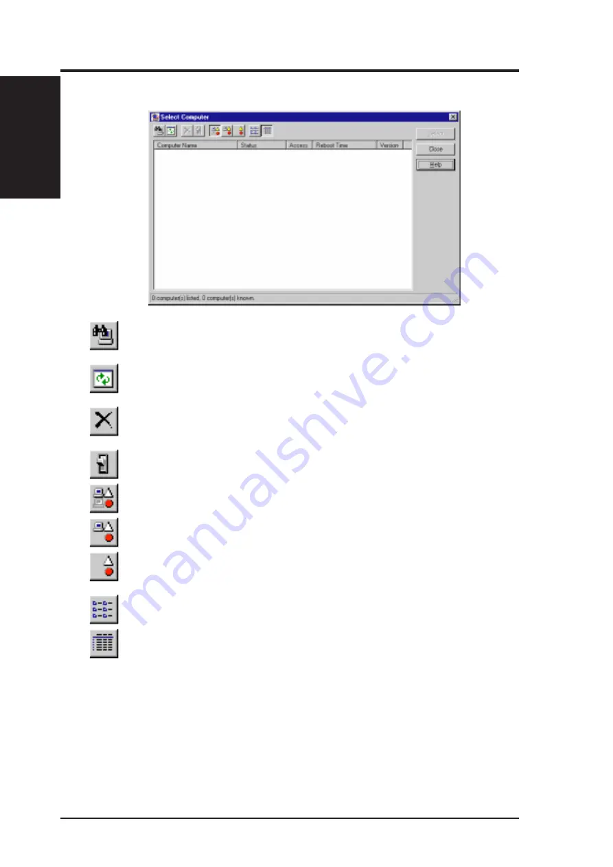
Using the Select Computer Dialog Box
Discovers new computers on the network
Refreshes the health of known computers
Removes a computer from the list of discovered computers
Wakes up a sleeping computer
Shows all discovered computers
Shows only available computers
Shows only unhealthy computers
Shows a simple list view
Shows a detailed list view
VI. S/W REFERENCE
Intel LDCM
Summary of Contents for MEL
Page 1: ...R MEL Socket 370 Motherboard USER S MANUAL ...
Page 58: ...ASUS MEL User s Manual 58 This page was intentionally left blank IV BIOS SETUP IV BIOS ...
Page 59: ...59 ASUS MEL User s Manual V SOFTWARE SETUP R ...
Page 73: ...ASUS MEL User s Manual 73 VI SOFTWARE REFERENCE VI S W REFERENCE AudioRack R ...


