


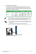


4.
USB connectors (10-1 pin USB56, USB78)
These connectors are for USB 2.0 ports. Connect the USB module cable to any of
these connectors, then install the module to a slot opening at the back of the system
chassis. These USB connectors comply with the USB 2.0 specification that supports up
to 480Mbps connection speed.
Never connect a 1394 cable to the USB connectors. Doing so will damage the
motherboard!
The USB 2.0 module is purchased separately.
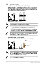
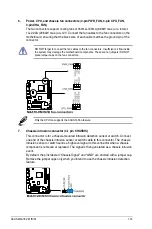
5.
Front panel audio connector (10-1 pin AAFP)
This connector is for a chassis-mounted front panel audio I/O module that supports
either High Definition Audio or AC`97 audio standard. Connect one end of the front
panel audio I/O module cable to this connector.
If you want to connect a high-definition front panel audio module to this connector, ensure
that the
Front Panel Type
item in the BIOS is set to
[HD Audio
]. If you want to connect
an AC97 front panel audio module to this connector, set the item to
[AC97]
. See
2.4.4
Onboard Devices Configuration
for details.
Chapter 1: Product introduction
1-13