background image

ASUS M2N4-SLI

4-13

4.2.4  Menu items

The highlighted item on the menu bar  displays the specific items for that 

menu. For example, selecting Main shows the Main menu items.
The other items (Advanced, Power, Boot, and Exit) on the menu bar have 

their respective menu items.

4.2.5  Sub-menu items

A solid triangle before each item on any menu screen means that the 

iteam has a sub-menu. To display the sub-menu, select the item and press 

<Enter>.

4.2.6  Configuration fields

These fields show the values for the menu items. If an item is 

user-configurable, you can change the value of the field opposite the item. 

You cannot select an item that is not user-configurable.
A configurable field is enclosed in brackets, and is highlighted when 

selected. To change the value of a field, select it then press <Enter> to 

display a list of options. Refer to “4.2.7 Pop-up window.”
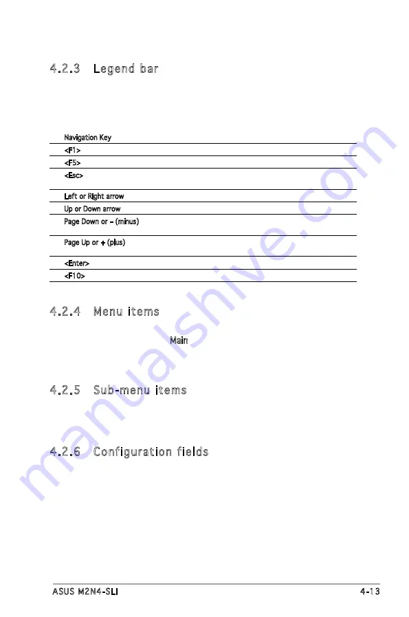
4.2.3  Legend bar

At the bottom of the Setup screen is a legend bar. The keys in the legend 

bar allow you to navigate through the various setup menus. The following 

table lists the keys found in the legend bar with their corresponding 

functions.

Navigation Key 

Function

<F1> 

Displays the General Help screen

<F5> 

Loads setup default values

<Esc> 

Exits the BIOS setup or returns to the main menu  


from a sub-menu

Left or Right arrow 

Selects the menu item to the left or right 

Up or Down arrow


Moves the highlight up or down between fields 

Page Down or – (minus) 

Scrolls backward through the values for the  


highlighted field

Page Up or + (plus)  

Scrolls forward through the values for the highlighted    


field

<Enter>


Brings up a selection menu for the highlighted field 

<F10> 

Saves changes and exit

Summary of Contents for M2N4-SLI

Page 1: ...Motherboard M2N4 SLI ...

Page 2: ...ARTICULAR PURPOSE IN NO EVENT SHALL ASUS ITS DIRECTORS OFFICERS EMPLOYEES OR AGENTS BE LIABLE FOR ANY INDIRECT SPECIAL INCIDENTAL OR CONSEQUENTIAL DAMAGES INCLUDING DAMAGES FOR LOSS OF PROFITS LOSS OF BUSINESS LOSS OF USE OR DATA INTERRUPTION OF BUSINESS AND THE LIKE EVEN IF ASUS HAS BEEN ADVISED OF THE POSSIBILITY OF SUCH DAMAGES ARISING FROM ANY DEFECT OR ERROR IN THIS MANUAL OR PRODUCT SPECIFIC...

Page 3: ... 1 Placement direction 2 2 2 2 2 Screw holes 2 2 2 2 3 Motherboard layout 2 3 2 2 4 Layout Contents 2 4 2 3 Central Processing Unit CPU 2 5 2 3 1 Installing the CPU 2 5 2 3 2 Installing the heatsink and fan 2 7 2 4 System memory 2 10 2 4 1 Overview 2 10 2 4 2 Memory configurations 2 10 2 4 3 Installing a DIMM 2 15 2 4 4 Removing a DIMM 2 15 2 5 Expansion slots 2 16 2 5 1 Installing an expansion ca...

Page 4: ...1 4 1 2 Updating the BIOS 4 2 4 1 3 Saving the current BIOS file 4 4 4 1 4 ASUS CrashFree BIOS 3 utility 4 5 4 1 5 ASUS EZ Flash 2 utility 4 7 4 1 6 ASUS Update utility 4 8 4 2 BIOS setup program 4 11 4 2 1 BIOS menu screen 4 12 4 2 2 Menu bar 4 12 4 2 3 Legend bar 4 13 4 2 4 Menu items 4 13 4 2 5 Sub menu items 4 13 4 2 6 Configuration fields 4 13 4 2 7 Pop up window 4 14 4 2 8 General help 4 14 ...

Page 5: ...Device Priority 4 37 4 6 2 Removable Drives 4 38 4 6 3 Hard Disk Drives 4 38 4 6 4 Boot Settings Configuration 4 39 4 6 5 Security 4 41 4 7 Tools menu 4 43 ASUS EZ Flash 2 4 43 4 8 Exit menu 4 44 Chapter 5 Software support 5 1 Installing an operating system 5 1 5 2 Support CD information 5 1 5 2 1 Running the support CD 5 1 5 2 2 Drivers menu 5 2 5 2 3 Utilities menu 5 3 5 2 4 Manuals menu 5 4 5 2...

Page 6: ...8 5 5 Creating a RAID driver disk 5 25 Chapter 6 NVIDIA SLI technology support 6 1 Overview 6 1 Requirements 6 1 6 2 Dual graphics card setup 6 2 6 2 1 Installing SLI ready graphics cards 6 2 6 2 2 Installing the device drivers 6 5 6 2 3 Enabling the multi GPU feature in Windows 6 5 ...

Page 7: ...ause harmful interference to radio or television reception which can be determined by turning the equipment off and on the user is encouraged to try to correct the interference by one or more of the following measures Reorient or relocate the receiving antenna Increase the separation between the equipment and receiver Connect the equipment to an outlet on a circuit different from that to which the...

Page 8: ...ould interrupt the grounding circuit Make sure that your power supply is set to the correct voltage in your area If you are not sure about the voltage of the electrical outlet you are using contact your local power company If the power supply is broken do not try to fix it by yourself Contact a qualified service technician or your retailer Operation safety Before installing the motherboard and add...

Page 9: ...ling system components It includes description of the switches jumpers and connectors on the motherboard Chapter 3 Powering up This chapter describes the power up sequence the vocal POST messages and ways of shutting down the system Chapter 4 BIOS setup This chapter tells how to change system settings through the BIOS Setup menus Detailed descriptions of the BIOS parameters are also provided Chapt...

Page 10: ...ed key Example Enter means that you must press the Enter or Return key Key1 Key2 Key3 If you must press two or more keys simultaneously the key names are linked with a plus sign Example Ctrl Alt D Command Means that you must type the command exactly as shown then supply the required item or value enclosed in brackets Example At the DOS prompt type the command line awdflash M2N4SLI ROM Where to fin...

Page 11: ...I ready graphics card ASUS two slot thermal design Storage NVIDIA nForce 4 SLI MCP supports 2 x IDE connector for up to four Ultra DMA 133 100 66 33 devices 4 x Serial ATA 3 0 Gb s connectors support four Serial ATA devices RAID 0 RAID 1 RAID 0 1 RAID 5 and JBOD configurations spanning across Serial ATA drives LAN NVIDIA nForce 4 SLI MCP built in Gigabit MAC with external Attansic PHY Supports TCP...

Page 12: ...vices 4 x Serial ATA connectors 1 x CPU 1 x Chassis 1 x Power fan connectors S PDIF out connector Front panel audio connector CD AUX audio in connectors 24 pin ATX power connector 4 pin ATX 12 V power connector System panel connector BIOS features 4 Mb BIOS ROM AWARD BIOS PnP DMI 2 0 WfM2 0 SM BIOS 2 3 Manageability WOL by PME WOR by PME Chassis intrusion PXE Power requirements ATX power supply wi...

Page 13: ...1 Product introduction This chapter describes the motherboard features and the new technologies it supports ...

Page 14: ...ASUS M2N4 SLI Chapter summary 1 1 Welcome 1 1 1 2 Package contents 1 1 1 3 Special features 1 2 ...

Page 15: ...our package with the list below If any of the above items is damaged or missing contact your retailer 1 2 Package contents Check your motherboard package for the following items Motherboard ASUS M2N4 SLI motherboard Cables 2 x Serial ATA signal cables 1 x Serial ATA power cable with dual plugs 1 x Ultra DMA 133 cable 1 x Floppy disk drive cable Accessories I O shield ASUS SLI bridge 1 x ASUS Q Con...

Page 16: ...GPUs to work together and achieve exceptional graphics performance See Chapter 6 for details AMD Cool n Quiet Technology The motherboard supports the AMD Cool n Quiet Technology that dynamically and automatically changes the CPU speed voltage and amount of power depending on the task the CPU performs See pages 4 25 5 3 and 5 9 Gigabit LAN The motherboard comes with a Gigabit LAN controller built i...

Page 17: ...ata in packets This high speed interface is software compatible with existing PCI specifications See page 2 18 for details S PDIF digital sound ready The motherboard supports the S PDIF Out function through the S PDIF interfaces on the rear panel The S PDIF technology turns your computer into a high end entertainment system with digital connectivity to powerful audio and speaker systems See page 2...

Page 18: ...riendly BIOS update utility Simply press the predefined hotkey to launch the utility and update the BIOS without entering the OS Update your BIOS easily without preparing a bootable diskette or using an OS based flash utility See page 4 7 for details ASUS Q Connector ASUS Q Connector allows you to easily connect or disconnect the chassis front panel cables to the motherboard This unique module eli...

Page 19: ... Hardware information This chapter lists the hardware setup procedures that you have to perform when installing system components It includes description of the jumpers and connectors on the motherboard ...

Page 20: ...US M2N4 SLI Chapter summary 2 1 Before you proceed 2 1 2 2 Motherboard overview 2 2 2 3 Central Processing Unit CPU 2 5 2 4 System memory 2 10 2 5 Expansion slots 2 16 2 6 Jumpers 2 19 2 7 Connectors 2 22 ...

Page 21: ...em See 8 ATX power connectors on page 2 26 for details Unplug the power cord from the wall socket before touching any component Use a grounded wrist strap or touch a safely grounded object or to a metal object such as the power supply case before handling components to avoid damaging them due to static electricity Hold components by the edges to avoid touching the ICs on them Whenever you uninstal...

Page 22: ...ysical injury and damage motherboard components Do not overtighten the screws Doing so can damage the motherboard 2 2 1 Placement direction When installing the motherboard make sure that you place it into the chassis in the correct orientation The edge with external ports goes to the rear part of the chassis as indicated in the image below 2 2 2 Screw holes Place six 6 screws into the holes indica...

Page 23: ..._IDE SEC_IDE USBPW56 USBPW78 USBPW910 USB910 FLOPPY USB78 USB56 SATA4 SATA3 SATA2 SATA1 CLRTC CHASSIS F_PANEL USBPW34 NVIDIA NF4 SLI CHA_FAN PWR_FAN USB12 LAN_USB34 FP_AUDIO SPDIF_OUT USBPW12 CD AUX PCIEX16_1 PCIEX1_1 PCIEX1_2 PCIEX16_2 PCI1 PCI2 DDR2 DIMM_A1 64 bit 240 pin module DDR2 DIMM_B1 64 bit 240 pin module DDR2 DIMM_A2 64 bit 240 pin module DDR2 DIMM_B2 64 bit 240 pin module EATXPWR AUDIO...

Page 24: ...el connector 20 8 pin PANEL 2 30 System power LED 2 pin LED Hard disk drive activity LED 2 pin IDE_LED System warning speaker 4 pin SPEAKER ATX power button soft off button 2 pin PWR Reset button 2 pin RESET 2 2 4 Layout Contents Slots Page 1 DDR2 DIMM slots 2 10 2 PCI slots 2 17 3 PCI Express x16 slot 2 18 4 PCI Express x1 slot 2 18 Rear panel connectors Page 1 PS 2 mouse port green 2 22 2 Parall...

Page 25: ... then lift it up to a 90º angle 2 3 Central Processing Unit CPU The motherboard comes with a 940 pin AM2 socket designed for the AMD Athlon 64 X2 AMD Athlon 64 FX AMD Athlon 64 and AMD Sempron processors Socket lever Make sure you use a CPU is designed for the AM2 socket The CPU fits in only one correct orientation DO NOT force the CPU into the socket to prevent bending the connectors on the socke...

Page 26: ...angle matches the socket corner with a small triangle 5 When the CPU is in place push down the socket lever to secure the CPU The lever clicks on the side tab to indicate that it is locked 6 Install a CPU heatsink and fan following the instructions that came with the heatsink package Gold triangle Small triangle ...

Page 27: ...bracket The retention module base is already installed on the motherboard upon purchase You do not have to remove the retention module base when installing the CPU or installing other motherboard components If you purchased a separate CPU heatsink and fan assembly make sure that a Thermal Interface Material is properly applied to the CPU heatsink or CPU before you install the heatsink and fan asse...

Page 28: ...racket lock to the retention module base A clicking sound denotes that the retention bracket is in place 4 Push down the retention bracket lock on the retention mechanism to secure the heatsink and fan to the module base Make sure that the fan and heatsink assembly perfectly fits the retention mechanism module base otherwise you cannot snap the retention bracket in place ...

Page 29: ...the CPU fan cable to the connector on the motherboard labeled CPU_FAN Do not forget to connect the CPU fan connector Hardware monitoring errors can occur if you fail to plug this connector R M2N4 SLI M2N4 SLI CPU Fan Connectors GND CPU FAN PWR CPU FAN IN CPU FAN PWM CPU_FAN ...

Page 30: ...rates the location of the DDR2 DIMM sockets Channel Sockets Channel A DIMM_A1 and DIMM_A2 Channel B DIMM_B1 and DIMM_B2 2 4 2 Memory configurations You may install 256 MB 512 MB 1 GB and 2GB unbuffered ECC non ECC DDR2 DIMMs into the DIMM sockets Recommended Memory Configurations Mode Sockets DIMM_A1 DIMM_A2 DIMM_B1 DIMM_B2 Single Channel Populated Populated Populated Populated Dual channel 1 Popu...

Page 31: ... Click the article titled 4GB memory installed but less memory size detected For dual channel memory configuration 2 you may install identical DIMMs in all four sockets OR install an identical DIMM pair in DIMM_A1 and DIMM_B1 yellow sockets and another identical DIMM pair in DIMM_A2 and DIMM_B2 black sockets Always use identical DDR2 DIMM pairs for dual channel model For optimum compatibility we r...

Page 32: ... HYB18T5121608BF 3 7 SS HYS64T32000HU 3 7 B V V V 512MB Qimonda HYB18T512800BF37 SS HYS64T64000HU 3 7 B V V V 1024MB Qimonda HYB18T512800BF37 DS HYS64T128020HU 3 7 B V 512MB Hynix HY5PS12821F C4 SS HYMP564U648 C4 V 1024MB Hynix HY5PS12821F C4 DS HYMP512U648 C4 V V V 1024MB Hynix HY5PS12821F C4 ECC DS HYMP512U728 C4 V V 512MB Hynix HY5PS12821FP C4 ECC SS HYMP564U728 C4 V V 512MB Hynix HY5PS12821AFP...

Page 33: ... 1024MB Infineon HYB18T512800BF3S ECC DS HYS72T128020HU 3S B V V V 256MB Infineon HYB18T512160BF 3S SS HYS64T32000HU 3S B V V 512MB Infineon HYB18T512800BF3S SS HYS64T64000HU 3S B V V V 1024MB Infineon HYB18T512800BF3S DS HYS64T128020HU 3S B V V V 512MB Hynix HY5PS12821AFP Y5 SS HYMP564U64AP8 Y5 V V V 1024MB Hynix HY5PS12821AFP Y5 DS HYMP512U64AP8 Y5 V V V 512MB Hynix HY5PS12821AFP Y5 ECC SS HYMP5...

Page 34: ...M378T6553CZ3 CE7 V V V 512MB Infineon HYB18T256800AF25 DS HYS64T64520HU 2 5 A V V V 512MB Hynix HY5PS12821BFP S5 SS HYMP564U64BP8 S5 V V V 1024MB Hynix HY5PS12821BFP S5 DS HYMP512U64BP8 S5 V V 512MB MICRON 5JAIIZ9DQQ SS MT8HTF6464AY 80EA3 V V V 1024MB MICRON 5JAIIZ9DQQ DS MT16HTF12864AY 80EA3 V V V 512MB MICRON 5ZD22D9GKX SS MT8HTF6464AY 80ED4 V V V 1024MB MICRON 5ZD22D9GKX DS MT16HTF12864AY 80ED4...

Page 35: ...ning clips snap back in place and the DIMM is properly seated 2 4 4 Removing a DIMM To remove a DIMM 1 Simultaneously press the retaining clips outward to unlock the DIMM 2 Remove the DIMM from the socket A DDR2 DIMM is keyed with a notch so that it fits in only one direction Do not force a DIMM into a socket to avoid damaging the DIMM The DDR2 DIMM sockets do not support DDR DIMMs DO not install ...

Page 36: ... seated on the slot 5 Secure the card to the chassis with the screw you removed earlier 6 Replace the system cover 2 5 2 Configuring an expansion card After installing the expansion card configure the it by adjusting the software settings 1 Turn on the system and change the necessary BIOS settings if any See Chapter 4 for information on BIOS setup 2 Assign an IRQ to the card Refer to the tables on...

Page 37: ...Time Clock 9 4 IRQ Holder for PCI Steering 10 5 IRQ Holder for PCI Steering 11 6 IRQ Holder for PCI Steering 12 7 PS 2 Compatible Mouse Port 13 8 Numeric Data Processor 14 9 Primary IDE Channel A B C D E F G H PCI Slot 1 shared PCI Slot 2 shared PCIe x16 slot 1 shared PCIe x16 slot 2 shared PCIe x1 slot 1 shared PCIe x1 slot 2 shared IRQ assignments for this motherboard 2 5 4 PCI slots The PCI slo...

Page 38: ...PCI Express x1 slot 2 5 5 PCI Express x1 slot This motherboard supports PCI Express x1 network cards SCSI cards and other cards that comply with the PCI Express specifications Refer to the figure below for the location of the slot 2 5 6 PCI Express x16 slots This motherboard supports PCI Express x16 graphics cards that comply with the PCI Express specifications Refer to the figure below for the lo...

Page 39: ...ep the cap on pins 2 3 for about 5 10 seconds then move the cap back to pins 1 2 4 Re install the battery 5 Plug the power cord and turn ON the computer 6 Hold down the Del key during the boot process and enter BIOS setup to re enter data Except when clearing the RTC RAM never remove the cap on CLRTC jumper default position Removing the cap will cause system boot failure You do not need to clear t...

Page 40: ... modes no power to CPU DRAM in slow refresh power supply in reduced power mode The USB device wake up feature requires a power supply that can provide 500mA on the 5VSB lead for each USB port otherwise the system would not power up The total current consumed must NOT exceed the power supply capability 5VSB whether under normal condition or in sleep mode R M2N4 SLI M2N4 SLI USB device Wake up USBPW...

Page 41: ...2 3 5VSB if you wish to wake up the computer when you press a key on the keyboard the default value is Disabled This feature requires an ATX power supply that can supply at least 1A on the 5VSB lead and a corresponding setting in the BIOS see section 2 5 5 APM Configuration R M2N4 SLI M2N4 SLI Keyboard Power Setting Default 5V 5VSB KBPWR 2 3 1 2 ...

Page 42: ... LED LAN port LAN port LED indications 4 Line In port light blue This port connects the tape CD DVD player or other audio sources 5 Line Out port lime This port connects a headphone or a speaker In 4 channel 6 channel and 8 channel configuration the function of this port becomes Front Speaker Out 6 Microphone port pink This port connects a microphone ACT LINK LED SPEED LED Status Description Statu...

Page 43: ... channel configuration Light Blue Line In Rear Speaker Out Rear Speaker Out Lime Line Out Front Speaker Out Front Speaker Out Pink Mic In Mic In Center Subwoofe Port Headset 4 channel 6 channel 2 channel 2 7 2 Internal connectors 1 Floppy disk drive connector 34 1 pin FLOPPY This connector is for the provided floppy disk drive FDD signal cable Insert one end of the cable to this connector then con...

Page 44: ...atch the covered hole on the Ultra DMA cable connector This prevents incorrect insertion when you connect the IDE cable Use the 80 conductor IDE cable for Ultra DMA 100 66 IDE devices Drive jumper setting Mode of device s Cable connector Single device Cable Select or Master Black Two devices Cable Select Master Black Slave Gray Master Master Black or gray Slave Slave R M2N4 SLI M2N4 SLI IDE Connec...

Page 45: ...ou intend to create a Serial ATA RAID set using these connectors enable the RAID Enabled item in the SATA Configuration sub menu in the BIOS See section 4 4 7 Onboard Device Configuration for details Connect the right angle side of the SATA signal cable to the SATA device or you may connect the right angle side of the SATA cable to the onboard SATA port to avoid placement conflict with huge graphi...

Page 46: ...ack wire of each cable matches the ground pin of the connector Do not forget to connect the fan cables to the fan connectors Lack of sufficient air flow inside the system may damage the motherboard components These are not jumpers DO NOT place jumper caps on the fan connectors The ASUS Q Fan function is supported using the CPU Fan CPU_FAN and Chassis Fan CHA_FAN connectors only R M2N4 SLI M2N4 SLI...

Page 47: ...rs then install the module to a slot opening at the back of the system chassis These USB connectors comply with USB 2 0 specification that supports up to 480 Mbps connection speed R M2N4 SLI M2N4 SLI USB 2 0 Connectors GND NC GND USB78 USB 5V USB_P8 USB_P8 USB 5V USB_P7 USB_P7 1 USB56 USB 5V USB_P6 USB_P6 GND NC USB 5V USB_P5 USB_P5 GND 1 1 USB 5V USB_P10 USB_P10 USB 5V USB_P9 USB_P9 GND GND USB91...

Page 48: ...ly plugs The power supply plugs are designed to fit these connectors in only one orientation Find the proper orientation and push down firmly until the connectors completely fit Do not forget to connect the 4 pin ATX 12 V power plug otherwise the system will not boot Use of a PSU with a higher power output is recommended when configuring a system with more power consuming devices The system may be...

Page 49: ... mounted front panel audio I O module that supports either HD or legacy AC 97 audio standard Connect one end of the front panel audio I O module cable to this connector R M2N4 SLI M2N4 SLI Internal Audio Connectors AUX White Right Audio Channel Left Audio Channel Ground Ground CD black Right Audio Channel Left Audio Channel Ground Ground R M2N4 SLI M2N4 SLI Front panel audio connector FP_AUDIO Lin...

Page 50: ...LED This 2 pin connector is for the HDD Activity LED Connect the HDD Activity LED cable to this connector The IDE LED lights up or flashes when data is read from or written to the HDD System warning speaker 4 pin SPEAKER This 4 pin connector is for the chassis mounted system warning speaker The speaker allows you to hear system beeps and warnings ATX power button soft off button 2 pin PWRSW This c...

Page 51: ...ector Step 1 Connect the front panel cables to their respective connectors on the ASUS Q Connector Refer to the labels on the Q Connector for proper connection and pin definition Step 2 Carefully connect the ASUS Q Connector to the System panel connector The ASUS Q Connector fits only in one orientation if it doesn t fit try reversing it When installed the Q connector appears as shown ...

Page 52: ...3 Powering up This chapter describes the power up sequence and ways of shutting down the system ...

Page 53: ...ASUS M2N4 SLI Chapter summary 3 3 1 Starting up for the first time 3 1 3 2 Powering off the computer 3 2 ...

Page 54: ...se lights up For systems with ATX power supplies the system LED lights up when you press the ATX power button If your monitor complies with green standards or if it has a power standby feature the monitor LED may light up or switch between orange and green after the system LED turns on The system then runs the power on self tests or POST While the tests are running the BIOS beeps or additional mes...

Page 55: ...ndows XP 1 Click the Start button then select Turn Off Computer 2 Click the Turn Off button to shut down the computer 3 The power supply should turn off after Windows shuts down 3 2 2 Using the dual function power switch While the system is ON pressing the power switch for less than four seconds puts the system to sleep mode or to soft off mode depending on the BIOS setting Pressing the power swit...

Page 56: ...4 BIOS setup This chapter tells how to change the system settings through the BIOS Setup menus Detailed descriptions of the BIOS parameters are also provided ...

Page 57: ...4 SLI Chapter summary 4 1 Managing and updating your BIOS 4 1 4 2 BIOS setup program 4 11 4 3 Main menu 4 15 4 4 Advanced menu 4 20 4 5 Power menu 4 32 4 6 Boot menu 4 37 4 7 Tools menu 4 43 4 8 Exit menu 4 44 ...

Page 58: ...te a bootable floppy disk DOS environment a Insert a 1 44MB floppy disk into the drive b At the DOS prompt type format A S then press Enter Windows XP environment a Insert a 1 44 MB floppy disk to the floppy disk drive b Click Start from the Windows desktop then select My Computer c Select the 3 1 2 Floppy Drive icon d Click File from the menu then select Format A Format 3 1 2 Floppy Disk window a...

Page 59: ...o a floppy disk Save only the updated BIOS file in the floppy disk to avoid loading the wrong BIOS file 2 Copy the AwardBIOS Flash Utility awdflash exe from the Software folder of the support CD to the floppy disk with the latest BIOS file 3 Boot the system in DOS mode using the bootable floppy disk you created earlier 4 When the A appears replace the bootable floppy disk with the floppy disk cont...

Page 60: ...f Power Or Reset System For NF KC804 M2N4 SLI DATE 11 18 2004 Flash Type SST 49LF004A B 3 3V File Name to Program m2n4sli bin Program Flashing Memory OFE00 OK Write OK No Update Write Fail Message Do You Want To Save Bios Y N 9 The utility displays a Flashing Complete message indicating that you have successfully flashed the BIOS file Remove the floppy disk then press F1 to restart the system Awar...

Page 61: ... m2n4sli bin Save current BIOS as AwardBIOS Flash Utility for ASUS V1 01 C Phoenix Technologies Ltd All Rights Reserved Message Please Wait For NF KC804 M2N4 SLI DATE 11 18 2004 Flash Type SST 49LF004A B 3 3V File Name to Program m2n4sli bin Checksum DAD6H Save current BIOS as m2n4sli2 bin AwardBIOS Flash Utility for ASUS V1 01 C Phoenix Technologies Ltd All Rights Reserved Message Please Wait For...

Page 62: ... the updating process Award BootBlock BIOS v1 0 Copyright c 2000 Award Software Inc BIOS ROM checksum error Detecting IDE ATAPI device Found CDROM try to Boot from it Pass When found the utility reads the BIOS file and starts flashing the corrupted BIOS file Award BootBlock BIOS v1 0 Copyright c 2000 Award Software Inc BIOS ROM checksum error Detecting IDE ATAPI device Recovering the BIOS from the...

Page 63: ... floppy disk for the original or updated BIOS file 4 Restart the system after the utility completes the updating process DO NOT shut down or reset the system while updating the BIOS Doing so can cause system boot failure When no CD is found the utility automatically checks the optical drive for the original or updated BIOS file The utility then updates the corrupted BIOS file Award BootBlock BIOS ...

Page 64: ...Test POST 2 Enter BIOS setup program Go to the Tools menu then select EZ Flash 2 and press Enter You can switch between drives by pressing Tab before the correct file is found Then press Enter 4 When the correct BIOS file is found EZ Flash 2 performs the BIOS update process and automatically reboots the system when done This function can support devices such as USB flash disk hard disk or floppy d...

Page 65: ...to manage save and update the motherboard BIOS in Windows environment The ASUS Update utility allows you to Save the current BIOS file Download the latest BIOS file from the Internet Update the BIOS from an updated BIOS file Update the BIOS directly from the Internet and View the BIOS version information This utility is available in the support CD that comes with the motherboard package ASUS Updat...

Page 66: ... Updating the BIOS through the Internet To update the BIOS through the Internet 1 Launch the ASUS Update utility from the Windows desktop by clicking Start Programs ASUS ASUSUpdate ASUSUpdate The ASUS Update main window appears 2 Select Update BIOS from the Internet option from the drop down menu then click Next ...

Page 67: ...date BIOS from a file option from the drop down menu then click Next 4 From the FTP site select the BIOS version that you wish to download Click Next 5 Follow the screen instructions to complete the update process The ASUS Update utility is capable of updating itself through the Internet Always update the utility to avail all its features 3 Locate the BIOS file from the Open window then click Open...

Page 68: ...h to enter Setup after POST reboot the system by doing any of the following procedures Restart using the OS standard shut down procedure Press Ctrl Alt Del simultaneously Press the reset button on the system chassis Press the power button to turn the system off then back on Using the power button reset button or the Ctrl Alt Del keys to force reset from a running operating system can cause damage ...

Page 69: ...4 2 2 Menu bar The menu bar on top of the screen has the following main items Main For changing the basic system configuration Advanced For changing the advanced system settings Power For changing the advanced power management APM configuration Boot For changing the system boot configuration Exit For selecting the exit options and loading default settings To select an item on the menu bar press th...

Page 70: ...ghted when selected To change the value of a field select it then press Enter to display a list of options Refer to 4 2 7 Pop up window 4 2 3 Legend bar At the bottom of the Setup screen is a legend bar The keys in the legend bar allow you to navigate through the various setup menus The following table lists the keys found in the legend bar with their corresponding functions Navigation Key Functio...

Page 71: ... capacity and physical size of diskette drive A 4 2 8 General help At the top right corner of the menu screen is a brief description of the selected item Pop up menu System Tim 15 30 36 System Date Wed Nov 5 2004 Legacy Diskette A 1 44M 3 5 in Primary IDE Master ST321122A Primary IDE Slave ASUS CDS520 A Secondary IDE Master None Secondary IDE Slave None First SATA Master None Second SATA Slave Non...

Page 72: ...for information on the menu screen items and how to navigate through them 4 3 1 System Time xx xx xx Allows you to set the system time 4 3 2 System Date Day xx xx xxxx Allows you to set the system date 4 3 3 Legacy Diskette A 1 44M 3 5 in Sets the type of floppy drive installed Configuration options Disabled 720K 3 5 in 1 44M 3 5 in System Tim 15 30 36 System Date Wed Nov 5 2004 Legacy Diskette A ...

Page 73: ...o automatically detect an IDE hard disk drive If automatic detection is successful the BIOS automatically fills in the correct values for the remaining fields on this sub menu If the hard disk was already formatted on a previous system the setup BIOS may detect incorrect parameters Select Manual to manually enter the IDE hard disk drive parameters If no drive is installed select None Configuration...

Page 74: ...le PIO Mode Sets the PIO mode for the IDE device Configuration options Auto Mode 0 Mode 1 Mode 2 Mode 3 Mode 4 UDMA Mode Disables or sets the UDMA mode Configuration options Disabled Auto Transfer Mode Shows the Transfer mode This item is not configurable After entering the IDE hard disk drive information into BIOS use a disk utility such as FDISK to partition and format new IDE hard disk drives T...

Page 75: ...cess Mode Sets the sector addressing mode Configuration options Large Auto F1 Help Select Item Change Value F5 Setup Defaults ESC Exit Select Menu Enter Select Sub menu F10 Save and Exit Phoenix Award BIOS CMOS Setup Utility Main Select Menu Item Specific Help Press Enter to select SATA 1 Extended IDE Drive Auto Access Mode Auto Capacity xxxxx MB Cylinder xxxxx Head xx Landing Zone xx Sector xx Be...

Page 76: ...d disk drive information into BIOS use a disk utility such as FDISK to partition and format new IDE hard disk drives This is necessary so that you can write or read data from the hard disk Make sure to set the partition of the Primary IDE hard disk drives to active 4 3 7 HDD SMART Monitoring Allows you to enable or disable the HDD Self Monitoring Analysis and Reporting Technology SMART feature Con...

Page 77: ...ct overclock profile JumperFree Configuration DRAMAI Tuning Auto x Overclock Options Disabled x CPU Frequency 200 0 x PCI Express Clock 100Mhz x DDR2 Voltage Auto x CPU Multiplier Auto x CPU Voltage Auto x PCI Clock Sychronization Mod Auto Phoenix Award BIOS CMOS Setup Utility Advanced 4 4 Advanced menu The Advanced menu items allow you to change the settings for the CPU and other system devices T...

Page 78: ...ltiple equals the CPU speed The value of this item is auto detected by BIOS The values range from 200 to 400 Refer to the following table for the correct Front Side Bus and CPU External Frequency settings The following items are user configurable only when the Overclock Profile item is set to Manual Selecting a very high CPU frequency may cause the system to become unstable If this happens revert ...

Page 79: ...age Auto Sets the operating CPU voltage The configuration options vary depending on the model of processor installed PCI Clock Synchronization Mode Auto Sets the PCI Clock Synchronization mode Configuration options Auto To CPU 33 33MHz ...

Page 80: ...is sub menu show the DRAM related information auto detected by the BIOS F1 Help Select Item Change Value F5 Setup Defaults ESC Exit Select Menu Enter Select Sub menu F10 Save and Exit Select Menu Item Specific Help Setting platform Memclock or limit valu DRAM Configuration Memory Clock Frequency Auto Tcl Auto Trcd Auto Trp Auto Tras Auto Trc Auto Twr Auto Trrd Auto Trwt Auto Twtr Auto Trtp Auto Tw...

Page 81: ...s Auto 11 12 13 14 15 16 17 18 19 20 21 22 23 24 25 26 Twr Auto Configuration options Auto 3 4 5 6 Trrd Auto Configuration options Auto 2 3 4 5 Trwt Auto Configuration options Auto 2 3 4 5 6 7 8 9 Twtr Auto Configuration options Auto 1 2 3 Trtp Auto Configuration options Auto 2 4 3 5 Twrrd Auto Configuration options Auto 0 1 2 3 Twrwr Auto Configuration options Auto 1 2 3 Trdrd Auto Configuration ...

Page 82: ...nge Value F5 Setup Defaults ESC Exit Select Menu Enter Select Sub menu F10 Save and Exit PCIPnP Plug Play O S No Primary Display Adapter PCI Phoenix Award BIOS CMOS Setup Utility Advanced 4 4 4 PCIPnP Plug Play O S No When set to No the BIOS configures all the devices in the system When set to Yes and if you install a Plug and Play operating system the operating system configures the Plug and Play...

Page 83: ...Utility Advanced F1 Help Select Item Change Value F5 Setup Defaults ESC Exit Select Menu Enter Select Sub menu F10 Save and Exit Select Menu Item Specific Help Onboard Device Configuration OnChip IDE Channel0 Enabled OnChip IDE Channel1 Enabled IDE DMA transfer access Enabled SATA Port 1 2 Enabled SATA DMA transfer Enabled SATA Port 3 4 Enabled SATA2 DMA transfer Enabled IDE Prefetch Enabled Phoen...

Page 84: ...bled Enabled SATA Port 3 4 Enabled Allows to disable or enable OnChip SATA2 Port 3 Port 4 Configuration options Disabled Enabled SATA2 DMA transfer Enabled Allows to disable or enable to switch to support SATA2 DMA tranfer Configuration options Disabled Enabled IDE Prefetch Mode Enabled Allows to disable or enable IDE PIO read prefetch mode When prefetch is enabled either 16 bit or 32 bit are allo...

Page 85: ...sabled Phoenix Award BIOS CMOS Setup Utility Advanced RAID Enable Disabled Allows to disable or enable nVIDIA RAID feature Configuration options Disabled Enabled IDE Primary Master RAID Disabled Selects this device as RAID set Configuration options Disabled Enabled IDE Primary Slave RAID Disabled Selects this device as RAID set Configuration options Disabled Enabled IDE Secondary Master RAID Disab...

Page 86: ...ed USB 2 0 Controller Enabled USB Legacy support Enabled Phoenix Award BIOS CMOS Setup Utility Advanced Second SATA Maser RAID Disabled Selects this device as RAID set Configuration options Disabled Enabled Third SATA Maser RAID Disabled Selects this device as RAID set Configuration options Disabled Enabled Fourth SATA Maser RAID Disabled Selects this device as RAID set Configuration options Disab...

Page 87: ...led Disabled AC97 Audio Enabled Enable or Disable Onboard AC 97 Configuration options Enabled Disabled Serial Port1 Address 3F8 IRQ4 Allows you to select the Serial Port1 base address Configuration options Disabled 3F8 IRQ4 2F8 IRQ3 3E8 IRQ4 2E8 IRQ3 Auto Parallel Port Address 378 IRQ7 Allows you to select the Parallel Port base addresses Configuration options Disabled 378 IRQ7 278 IRQ5 3BC IRQ7 P...

Page 88: ...f SLI EZ Selector Card Set to Normal when using single PCI E graphic cardpluged Configuration Auto Single Video Card Dual Video Card F1 Help Select Item Change Value F5 Setup Defaults ESC Exit Select Menu Enter Select Sub menu F10 Save and Exit Select Menu Item Specific Help SLI Configuration AI Selector Auto Phoenix Award BIOS CMOS Setup Utility Advanced ...

Page 89: ...pport Enabled APM Configuration Hardware Monitor F1 Help Select Item Change Value F5 Setup Defaults ESC Exit Select Menu Enter Select Sub menu F10 Save and Exit 4 5 1 ACPI Suspend Type S1 S3 Allows you to select the Advanced Configuration and Power Interface ACPI state to be used for system suspend Configuration options S1 POS S3 STR S1 S3 4 5 2 ACPI APIC Support Enabled Allows you to enable or di...

Page 90: ...ff Power On PWR Button 4 secs Instant Off Allows you to set the event after the power button is pressed for more than 4 seconds Configuration options Suspend Instant Off Power On By PCI Devices Disabled When set to Enabled this parameter allows you to turn on the system through a PCI LAN or modem card This feature requires an ATX power supply that provides at least 1A on the 5VSB lead Configuratio...

Page 91: ... for the hour field 2 Key in a value Min 0 Max 23 then press Enter 3 Press TAB to move to the minutes field then press Enter 4 Key in a minute value Min 0 Max 59 then press Enter 5 Press TAB to move to the seconds field then press Enter 6 Key in a value Min 0 Max 59 then press Enter Power Up By PS 2 Mouse Disabled When set to Enabled this parameter allows you to use the PS 2 mouse to turn on the s...

Page 92: ...V 12V Voltage 11 26V CPU Temperature 48ºC M B Temperature 38ºC CPU FAN Speed 4962 RPM CHA FAN Speed 0 RPM Power FAN Speed 5443 RPM CPU Fan Speed warning 880 RPM Phoenix Award BIOS CMOS Setup Utility Power CPU Chassis Q Fan Control Disabled Allows you to enable or disable the CPU Chassis Q Fan controller Configuration options Disabled Enabled CPU Chassis Q Fan Profile Performance Allows you to set ...

Page 93: ...an Speed The onboard hardware monitor automatically detects and displays the Chassis CPU and power fan speeds in rotations per minute RPM If the fan is not connected to the motherboard the field shows 0 These items are not user configurable CPU Fan Speed warning 800 RPM Enables or disables the CPU Fan speed warning feature Configuration options Disabled 800 RPM 1200 RPM 1600 RPM Please be careful ...

Page 94: ... Exit 4 6 1 Boot Device Priority 1st xxth Boot Device Removable These items specify the boot device priority sequence from the available devices The number of device items that appears on the screen depends on the number of devices installed in the system Configuration options Removable Hard Disk CDROM Disabled F1 Help Select Item Change Value F5 Setup Defaults ESC Exit Select Menu Enter Select Su...

Page 95: ...ist Press ESC to exit this menu Removable Drives 1 Floppy Disks Phoenix Award BIOS CMOS Setup Utility Boot 4 6 3 Hard Disk Drives 1 1st Master XXXXXXXXX Allows you to assign hard disk drives attached to the system F1 Help Select Item Change Value F5 Setup Defaults ESC Exit Select Menu Enter Select Sub menu F10 Save and Exit Select Menu Item Specific Help Use or to select a device then press to mov...

Page 96: ... Typematic Rate Chars Sec 6 x Typematic Delay Msec 250 OS Select For DRAM 64MB Non OS2 Full Screen LOGO Enabled Halt On All But Keyboard Phoenix Award BIOS CMOS Setup Utility Boot Case Open Warning Enabled Enables or disables the chassis open status feature Setting to Enabled clears the chassis open status Refer to section 2 7 Internal connectors for setting details Configuration options Disabled ...

Page 97: ...elect the rate at which a character repeats when you hold a key Configuration options 6 8 10 12 15 20 24 30 Typematic Delay Msec 250 Allows you to set the delay before keystrokes begin to repeat Configuration options 250 500 750 1000 OS Select for DRAM 64MB Non OS2 Set this item to OS2 only when you are running on an OS 2 operating system with an installed RAM of greater than 64 KB Configuration o...

Page 98: ...ervisor Password User Password These fields allow you to set passwords To set a password 1 Select an item then press Enter 2 Type in a password using a combination of a maximum of eight 8 alpha numeric characters then press Enter 3 When prompted confirm the password by typing the exact characters again then press Enter The password field setting is changed to Set To clear the password 1 Select the...

Page 99: ...by erasing the CMOS Real Time Clock RTC RAM The RAM data containing the password information is powered by the onboard button cell battery If you need to erase the CMOS RAM refer to section 2 6 Jumpers for instructions Password Check This field requires you to enter the password before entering the BIOS setup or the system Select Setup to require the password before entering the BIOS Setup Select ...

Page 100: ...ion screen use the left or right arrows to select Yes or No then press Enter See page 4 5 for details The following screen appears if you select Yes Follow screen instructions to flash the BIOS ASUSTek EZ Flash 2 BIOS ROM Utility B311 FLASH TYPE Winbond W39V080A 8Mb LPC BOARD M2NSLI Deluxe VER 0122 bin DATE 05 12 2006 Current ROM Update ROM BOARD Unknown VER Unknown DATE Unknown PATH C M2N320C A C...

Page 101: ... menu to ensure the values you selected are saved to the CMOS RAM An onboard backup battery sustains the CMOS RAM so it stays on even when the PC is turned off When you select this option a confirmation window appears Select Yes to save changes and exit Pressing Esc does not immediately exit this menu Select one of the options from this menu or F10 from the legend bar to exit Exit Discard Changes ...

Page 102: ...irmation window appears Select Yes to load default values Select Exit Save Changes or make other changes before saving the values to the non volatile RAM Discard Changes This option allows you to discard the selections you made and restore the previously saved values After selecting this option a confirmation appears Select Yes to discard any changes and load the previously saved values ...

Page 103: ...5 Software support This chapter describes the contents of the support CD that comes with the motherboard package ...

Page 104: ...ASUS M2N4 SLI Chapter summary 5 1 Installing an operating system 5 1 5 2 Support CD information 5 1 5 3 Software information 5 8 5 4 RAID configurations 5 16 5 5 Creating a RAID driver disk 5 25 ...

Page 105: ...es that you can install to avail all motherboard features 5 2 1 Running the support CD Place the support CD to the optical drive The CD automatically displays the Drivers menu if Autorun is enabled in your computer Motherboard settings and hardware options vary Use the setup procedures presented in this chapter for reference only Refer to your OS documentation for detailed information Make sure th...

Page 106: ...cessary drivers to activate the devices NVIDIA nForce Chipset Driver Installs the NVIDIA Chipset drivers for the NVIDIA nForce 4 SLI chipset Realtek Audio Driver Installs the Realtek audio driver and application AMD Cool n Quiet Driver Installs the AMD Cool n Quiet driver and application USB 2 0 Driver Installs the Universal Serial Bus 2 0 USB 2 0 driver ...

Page 107: ... operating condition ASUS Update Allows you to download the latest version of the BIOS from the ASUS website Before using the ASUS Update make sure that you have an Internet connection so you can connect to the ASUS website ASUS Screen Saver Bring life to your computer screen by installing the ASUS screen saver ASUS AMD Cool n Quiet Utility Installs the AMD Cool n Quiet software ADOBE Acrobat Read...

Page 108: ... for this motherboard model NVIDIA RAID User s Guide Allows you to open the NVIDIA RAID User s Guide Microsoft DirectX Installs the Microsoft DirectX 9 0 driver The Microsoft DirectX 9 0 is a multimedia technology that enhances computer graphics and sound DirectX improves the multimedia features of you computer so you can enjoy watching TV and movies capturing videos or playing games in your compu...

Page 109: ...information on the inside front cover of this user guide 5 2 6 Other information The icons on the top right corner of the screen give additional information on the motherboard and the contents of the support CD Click an icon to display the specified information Motherboard Info Displays the general specifications of the motherboard ...

Page 110: ...oftware support Browse this CD Displays the support CD contents in graphical format Technical support Form Displays the ASUS Technical Support Request Form that you have to fill out when requesting technical support ...

Page 111: ...ASUS M2N4 SLI 5 Filelist Displays the contents of the support CD and a brief description of each in text format ...

Page 112: ...er Option Properties depending on your operating system Windows 2000 XP 1 From the Windows 2000 XP operating system click the Start button Select Settings then Control Panel 2 Make sure the Control Panel is set to Classic View 3 Double click the Display icon in the Control Panel then select the Screen Saver tab 4 Click the Power button The following dialog box appears 5 From the Power schemes comb...

Page 113: ... the Cool n Quiet software that enables you to view your system s real time CPU Frequency and voltage To launch the Cool n Quiet program 1 If you are using Windows 2000 click the Start button Select Programs ASUS Cool Quiet Cool Quiet 2 If you are using Windows XP click the Start button Select All Programs ASUS Cool Quiet Cool Quiet 3 The Cool n Quiet technology screen appears and displays the cur...

Page 114: ...tup exe file from the ASUS PC Probe II folder Double click the setup exe file to start installation 2 Click the Utilities tab then click ASUS PC Probe II 3 Follow the screen instructions to complete installation Launching PC Probe II You can launch the PC Probe II right after installation or anytime from the Windows desktop To launch the PC Probe II from the Windows desktop click Start All Program...

Page 115: ... window Shows Hides the Preference section Minimizes the application Closes the application Sensor alert When a system sensor detects a problem the main window right handle turns red as the illustrations below show When displayed the monitor panel for that sensor also turns red Refer to the Monitor panels section for details Preferences You can customize the application using the Preference sectio...

Page 116: ...nels The hardware monitor panels display the current value of a system sensor such as fan rotation CPU temperature and voltages The hardware monitor panels come in two display modes hexagonal large and rectangular small When you check the Enable Monitoring Panel option from the Preference section the monitor panels appear on your computer s desktop Large display Small display Click to increase val...

Page 117: ...plays various Windows management information Click an item from the left panel to display on the right panel Click the plus sign before WMI Information to display the available information You can enlarge or reduce the browser size by dragging the bottom right corner of the browser DMI browser Click to display the DMI Desktop Management Interface browser This browser displays various desktop and s...

Page 118: ...ys real time information on the CPU hard disk drive space and memory usage Click to display the Usage browser CPU usage The CPU tab displays real time CPU usage in line graph representation Hard disk drive space usage The Hard Disk tab displays the used and available hard disk drive space The left panel of the tab lists all logical drives Click a hard disk drive to display the information on the r...

Page 119: ...t the sensor threshold values The Config window has two tabs Sensor Threshold and Preference The Sensor Threshold tab enables you to activate the sensors or to adjust the sensor threshold values The Preference tab allows you to customize sensor alerts or change the temperature scale Loads the default threshold values for each sensor Applies your changes Cancels or ignores your changes Loads your s...

Page 120: ...ta having to be calculated and written With the RAID 0 1 configuration you get all the benefits of both RAID 0 and RAID 1 configurations Use four new hard disk drives or use an existing drive and three new drives for this setup RAID 5 stripes both data and parity information across three or more hard disk drives Among the advantages of RAID 5 configuration include better HDD performance fault tole...

Page 121: ...the power connector on each drive Installing Serial ATA SATA hard disks To install the SATA hard disks for a RAID configuration 1 Install the SATA hard disks into the drive bays 2 Connect the SATA signal cables 3 Connect a SATA power cable to the power connector on each drive If you want to boot the system from a hard disk drive included in a RAID set copy first the RAID driver from the support CD...

Page 122: ...ration To set the BIOS RAID items 1 Boot the system and press Del during the Power On Self Test POST to enter the BIOS Setup Utility 2 From the Advanced Onboard Devices Configuration NVRAID Configuration menu item in the BIOS set the RAID Enabled item to Enabled The succeeding items become user configurable 3 Select and enable the IDE or SATA drive s that you want to configure as RAID See section ...

Page 123: ...hese keys allow you to move through and select menu options NVIDIA RAID Utility Oct 5 2004 Define a New Array RAID Mode Striping Striping Block Optimal Free Disks Array Disks Loc Disk Model Name Loc Disk Model Name 1 0 M XXXXXXXXXXXXXXXXXX 1 1 M XXXXXXXXXXXXXXXXXX Add 2 0 M XXXXXXXXXXXXXXXXXX 2 1 M XXXXXXXXXXXXXXXXXX Del Creating a RAID Volume To create a RAID volume 1 From the NVIDIA RAID utility...

Page 124: ...e the up or down arrow keys to select the stripe size for your RAID 0 array then press Enter The available values range from 8 KB to 128 KB The default selection is 128 KB The strip value should be chosen based on the planned drive usage 8 16 KB low disk usage 64 KB typical disk usage 128 KB performance disk usage 3 Press TAB to select the Free Disks area Use the left or right arrow keys to assign...

Page 125: ...5 2004 Array List Boot Id Status Vendor Array Model Name No 4 Healthy NVIDIA MIRROR XXX XXG A new set of navigation keys is displayed on the bottom of the screen 6 Press Ctrl X to save settings and exit R Rebuild D Delete C Clear Disk ENTER Return Array 1 NVIDIA MIRROR XXX XXG Array Detail RAID Mode Mirroring Striping Width 1 Striping Block 64K Adapt Channel M S Index Disk Model Name Capacity 2 1 ...

Page 126: ...lowing confirmation message appears Select F6 Back F7 Finish Array 1 NVIDIA MIRROR XXX XXG Select Disk Inside Array RAID Mode Mirroring Striping Width 1 Striping Block 64K Adapt Channel M S Index Disk Model Name Capacity 2 1 Master 0 XXXXXXXXXXXXXXXXX XXX XXGB 1 0 Master 1 XXXXXXXXXXXXXXXXX XXX XXGB Rebuild array ENTER OK ESC Cancel 4 Press Enter to start rebuilding array or press Esc to cancel 5 ...

Page 127: ...Width 1 Striping Block 64K Adapt Channel M S Index Disk Model Name Capacity 2 1 Master 0 XXXXXXXXXXXXXXXXX XXX XXGB 1 0 Master 1 XXXXXXXXXXXXXXXXX XXX XXGB A new set of navigation keys is displayed on the bottom of the screen 2 Press D to delete a RAID array The following confirmation message appears Delete this array Y YES N No 4 If you selected Yes the Define a New Array menu appears Take cautio...

Page 128: ...Detail RAID Mode Mirroring Striping Width 1 Striping Block 64K Adapt Channel M S Index Disk Model Name Capacity 2 1 Master 0 XXXXXXXXXXXXXXXXX XXX XXGB 1 0 Master 1 XXXXXXXXXXXXXXXXX XXX XXGB A new set of navigation keys is displayed on the bottom of the screen 2 Press C to clear disk The following confirmation message appears Take caution in using this option All data on the RAID drives will be l...

Page 129: ...to Drivers Chipset WINXP_2K Driver_Disk for the NVIDIA RAID driver disk utility Go to Drivers Sil3114 for the Silicon Image RAID driver disk utility 4 Insert floppy disk to floppy disk drive 5 Follow succeeding screen information to complete process 6 Write protect the floppy disk to avoid computer virus infection To install the RAID driver 1 During the OS installation the system prompts you to pr...

Page 130: ...5 26 Chapter 5 Software support ...

Page 131: ...6 This chapter tells how to install SLI ready PCI Express graphics cards NVIDIA SLI technology support ...

Page 132: ...ASUS M2N4 SLI Chapter summary 6 1 Overview 6 1 6 2 Dual graphics cards setup 6 2 ...

Page 133: ...ualified SLI ready graphics cards for this motherboard Make sure that your graphics card driver supports the NVIDIA SLI technology Download the latest driver from the NVIDIA website www nvidia com Make sure that your power supply unit PSU can provide at least the minimum power required by your system See 8 ATX power connectors on page 2 26 for details The NVIDIA SLI technology supports Windows XP ...

Page 134: ...ics cards that are ASUS and NVIDIA certified Different types of graphics cards will not work together properly To install the graphics cards 1 Prepare two graphics cards Each graphics card should have goldfingers for the SLI connector 2 Remove the metal bracket covers opposite the two PCI Express x16 slots 6 2 Dual graphics card setup ...

Page 135: ...labeled PCIEX16_2 Make sure that the card is properly seated on the slot If required connect an auxiliary power source to the PCI Express graphics cards 3 Insert one graphics card into the blue slot labeled PCIEX16_1 Make sure that the card is properly seated on the slot ...

Page 136: ...exible cable connector to the goldfingers on each graphics card Make sure that the connector is firmly in place 6 If using a 20 pin ATX power connector connect a 4 pin ATX power cable to the EZ Plug labeled EZ_PLUG on your motherboard The onboard red warning LED lights up if you do not plug a 4 pin ATX power cable to the EZ Plug SLI flexible cable connector ASUS EZ Plug ...

Page 137: ...Settings icon To enable the multi GPU feature 1 Click the NVIDIA Settings icon on your Windows taskbar 2 From the pop up menu select nView Desktop Manager then click nView Properties 6 2 3 Enabling the multi GPU feature in Windows After installing your graphics cards and the device drivers enable the Multi Graphics Processing Unit GPU feature in the NVIDIA nView properties 3 From the nView Desktop...

Page 138: ...der to display the following screen then select the SLI multi GPU item Slider 5 From the Display Properties dialog box select the Settings tab then click Advanced 6 Select the NVIDIA GeForce tab 8 Click the Enable SLI multi GPU check box 9 Click OK when done ...

Reviews: