


4
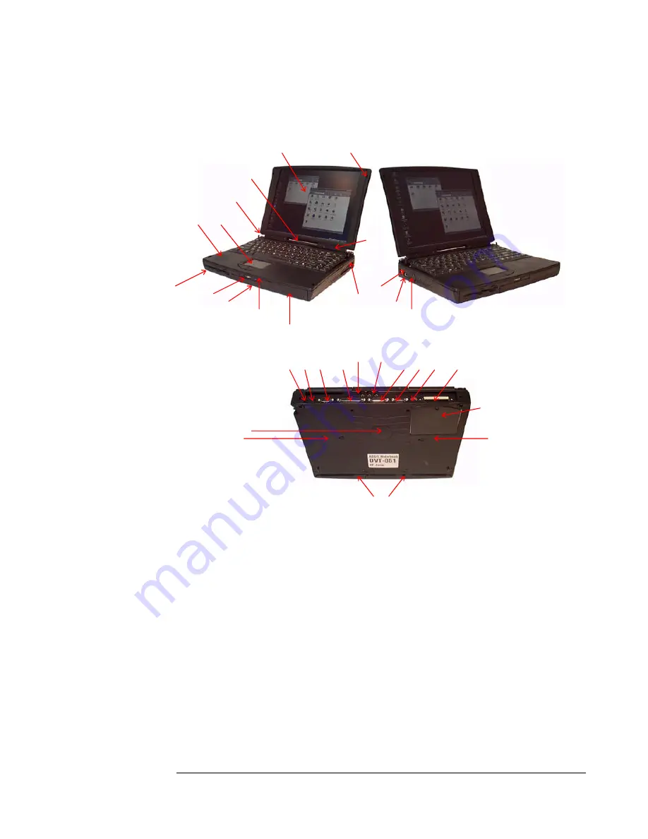
ASUS P6000 Key Parts Point Out
The illustrations below point out key parts of the P6000.
1. Microphone
2. Latches
3. TFT panel
4. Status panel
5. Keyboard support
6. Touch Pad
7. Speaker
8. PCMCIA
9. Battery
10. Hard disk drive
11. Charging light
12. Power switch/power light
13 FDD/CD ROM drive
14. Fan
15 USB port
16. External keyboard/mouse port
17. Docking port connector
18. NTSC/PAL video output
19. SVGA output
20. MIDI/joystick port
21. Audio jacks
22. Parallel port
23. Infrared port
24. Serial port
25. AC adapter socket
26.Reset button
27. BIOS upgrade socket.
28. Battery release key
29. Hard disk release screw
30. CD ROM release key
31. Memory upgrade socket
3
2
15
16
8
11
12
13
7
6
5
3
4
1
14
10
9
21
22
17
18
19
20
23
24
25
26
31
30
29
28
27


