Chapter 2
–
Hardware Information
37
G
ENE
SY
S C
omp
act
E
mb
ed
ded
S
ystem
G
ENE
SY
S-
W
HU6
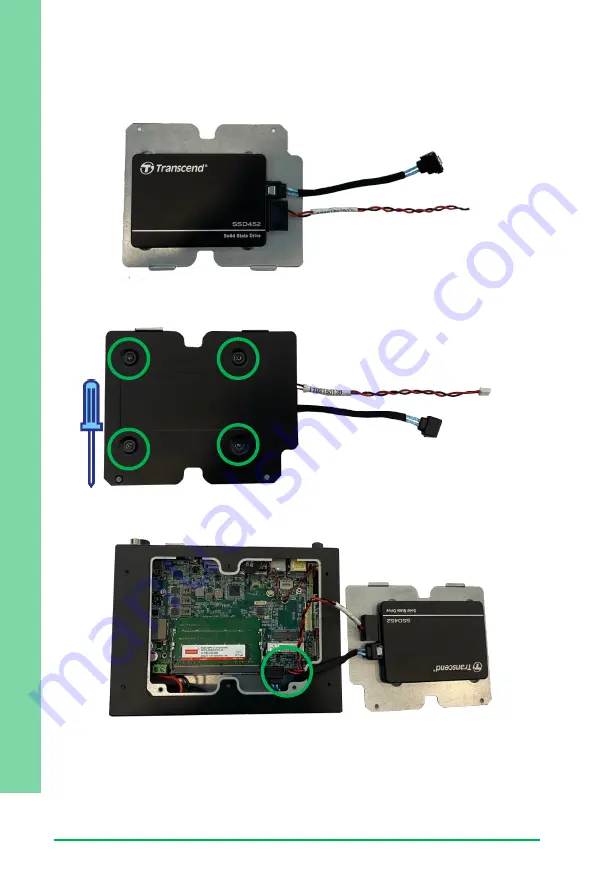
Step 2: Line up the mounting holes on the SATA drive with the four mounting points
on the bottom panel. Note the orientation of the cables.
Step 3: Secure the drive with four black mounting screws.
Step 4: Insert the SATA Cable into CN2 and SATA Power Cable into CN1.
If you are finished with hardware installation, replace the back panel and secure with
two black screws. Otherwise, continue to the next section for COM Port installation.
Summary of Contents for Aaeon GENESYS-WHU6
Page 1: ...Last Updated March 16 2021 GENESYS WHU6 GENESYS Compact Embedded System User s Manual 1st Ed ...
Page 14: ...GENESYS Compact Embedded System GENESYS WHU6 Chapter 1 Chapter 1 Product Specifications ...
Page 17: ...Chapter 1 Product Specifications 4 GENESYS Compact Embedded System GENESYS WHU6 I O Touch ...
Page 18: ...GENESYS Compact Embedded System GENESYS WHU6 Chapter 2 Chapter 2 Hardware Information ...
Page 20: ...Chapter 2 Hardware Information 7 GENESYS Compact Embedded System GENESYS WHU6 GENE WHU6 Board ...
Page 58: ...GENESYS Compact Embedded System GENESYS WHU6 Chapter 3 Chapter 3 AMI BIOS Setup ...
Page 85: ...GENESYS Compact Embedded System GENESYS WHU6 Chapter 4 Chapter 4 Driver Installation ...
Page 88: ...GENESYS Compact Embedded System GENESYS WHU6 Appendix A Appendix A I O Information ...
Page 92: ...Appendix A I O Information 79 GENESYS Compact Embedded System GENESYS WHU6 ...


