Chapter 3
–
BIOS Setup
47
EPIC
Bo
ar
d
EPIC
-C
FS
7-
PUC
3.4.3.1
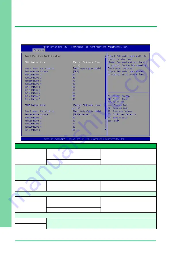
Smart Fan Mode Configuration
Auto Duty-Cycle Mode
Options Summary
FAN1 Output
Mode
Output PWM mode (open drain)
Linear Fan Application
Output PWM mode (push pull) Optimal Default, Failsafe Default
Output PWM mode (push pull) to control 4-wire fans.
Linear fan application circuit to control 3-
wire fan speed by fan’s power terminal.
Output PWM mode (open drain) to control Intel 4-wire fans.
Fan Mode
Auto RPM Mode
Auto Duty-Cycle Mode
Optimal Default, Failsafe Default
Smart Fan Mode Select
Temperature
Source
CPU
CPU (external)
Optimal Default, Failsafe Default
System
Select the monitored temperature source for this fan.
Duty Cycle
Auto fan speed control. Fan speed will follow different temperature
by different duty cycle 1-100
Temperature
Summary of Contents for Aaeon EPIC-CFS7-PUC
Page 1: ...Last Updated May 6 2021 EPIC CFS7 PUC EPIC Board User s Manual 1st Ed ...
Page 14: ...EPIC Board EPIC CFS7 PUC Chapter 1 Chapter 1 Product Specifications ...
Page 17: ...4 EPIC Board EPIC CFS7 PUC Chapter 2 Chapter 2 Hardware Information ...
Page 18: ...Chapter 2 Hardware Information 5 EPIC Board EPIC CFS7 PUC 2 1 Dimensions System ...
Page 19: ...Chapter 2 Hardware Information 6 EPIC Board EPIC CFS7 PUC Board ...
Page 20: ...Chapter 2 Hardware Information 7 EPIC Board EPIC CFS7 PUC POE Carrier Board DIO Carrier Board ...
Page 21: ...Chapter 2 Hardware Information 8 EPIC Board EPIC CFS7 PUC 2 2 Jumpers and Connectors ...
Page 22: ...Chapter 2 Hardware Information 9 EPIC Board EPIC CFS7 PUC ...
Page 50: ...Chapter 2 Hardware Information 37 EPIC Board EPIC CFS7 PUC 2 8 Block Diagrams ...
Page 51: ...Chapter 2 Hardware Information 38 EPIC Board EPIC CFS7 PUC ...
Page 52: ...39 EPIC Board EPIC CFS7 PUC Chapter 3 Chapter 3 BIOS Setup ...
Page 55: ...Chapter 3 BIOS Setup 42 EPIC Board EPIC CFS7 PUC 3 3 Setup Submenu Main ...
Page 56: ...Chapter 3 BIOS Setup 43 EPIC Board EPIC CFS7 PUC 3 4 Setup Submenu Advanced ...
Page 59: ...Chapter 3 BIOS Setup 46 EPIC Board EPIC CFS7 PUC 3 4 3 Hardware Monitor ...
Page 63: ...Chapter 3 BIOS Setup 50 EPIC Board EPIC CFS7 PUC 3 4 4 SIO Configuration ...
Page 68: ...Chapter 3 BIOS Setup 55 EPIC Board EPIC CFS7 PUC 3 5 Setup Submenu Chipset ...
Page 69: ...Chapter 3 BIOS Setup 56 EPIC Board EPIC CFS7 PUC 3 5 1 System Agent SA Configuration ...
Page 76: ...Chapter 3 BIOS Setup 63 EPIC Board EPIC CFS7 PUC 3 7 1 BBS Priorities ...
Page 77: ...Chapter 3 BIOS Setup 64 EPIC Board EPIC CFS7 PUC 3 8 Setup Submenu Save Exit ...
Page 78: ...65 EPIC Board EPIC CFS7 PUC Chapter 4 Chapter 4 Driver Installation ...
Page 81: ...EPIC Board EPIC CFS7 PUC Appendix A Appendix A I O Information ...
Page 82: ...Appendix A I O Information 69 EPIC Board EPIC CFS7 PUC A 1 I O Address Map ...
Page 83: ...Appendix A I O Information 70 EPIC Board EPIC CFS7 PUC ...
Page 84: ...Appendix A I O Information 71 EPIC Board EPIC CFS7 PUC ...
Page 85: ...Appendix A I O Information 72 EPIC Board EPIC CFS7 PUC A 2 Memory Address Map ...
Page 86: ...Appendix A I O Information 73 EPIC Board EPIC CFS7 PUC A 3 IRQ Mapping Chart ...
Page 87: ...Appendix A I O Information 74 EPIC Board EPIC CFS7 PUC ...
Page 88: ...Pico ITX Board EPIC CFS7 PUC Appendix B Appendix B Watchdog Timer Programming ...


