background image

5-6

Chapter 5: Software support

5.2.6 

ASUS Contact information

Click the Contact tab to display the ASUS contact information. You can also find 

this information on the inside front cover of this user guide.
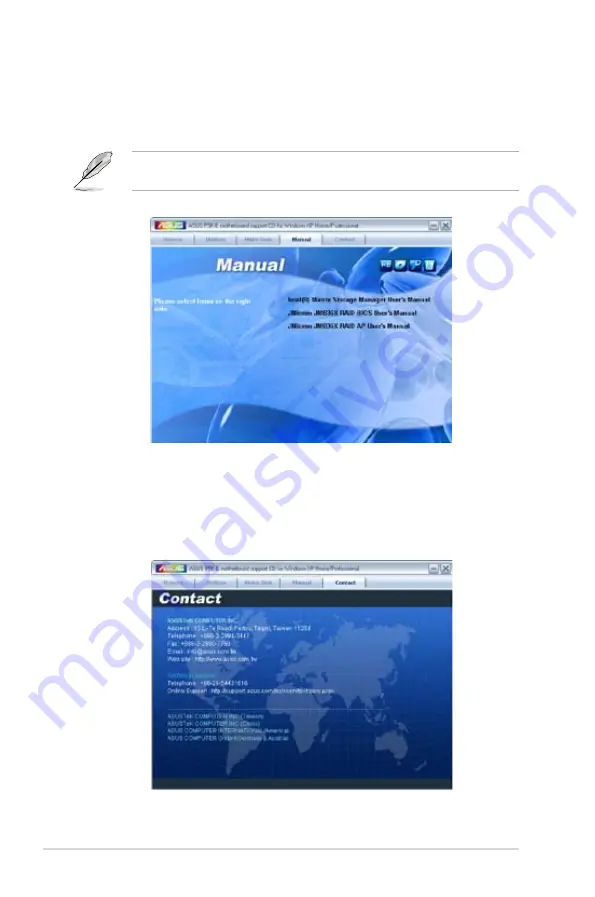
5.2.5 

Manual menu

The Manual menu contains a list of supplementary user manuals. Click an item to 

open the folder of the user manual.

Most user manual files are in Portable Document Format (PDF). Install the Adobe

®


Acrobat

®

 Reader from the Utilities menu before opening a user manual file.

Summary of Contents for 90-MBB6U1-G0EAY00Z - P5K-E/WIFI-AP AiLifestyle Series Motherboard

Page 1: ...Motherboard P5K E WiFi AP ...

Page 2: ...MERCHANTABILITY OR FITNESS FOR A PARTICULAR PURPOSE IN NO EVENT SHALL ASUS ITS DIRECTORS OFFICERS EMPLOYEES OR AGENTS BE LIABLE FOR ANY INDIRECT SPECIAL INCIDENTAL OR CONSEQUENTIAL DAMAGES INCLUDING DAMAGES FOR LOSS OF PROFITS LOSS OF BUSINESS LOSS OF USE OR DATA INTERRUPTION OF BUSINESS AND THE LIKE EVEN IF ASUS HAS BEEN ADVISED OF THE POSSIBILITY OF SUCH DAMAGES ARISING FROM ANY DEFECT OR ERROR ...

Page 3: ... 2 2 2 2 1 Placement direction 2 2 2 2 2 Screw holes 2 2 2 2 3 Motherboard layout 2 3 2 2 4 Layout contents 2 4 2 3 Central Processing Unit CPU 2 6 2 3 1 Installing the CPU 2 7 2 3 2 Installing the CPU heatsink and fan 2 9 2 3 3 Uninstalling the CPU heatsink and fan 2 11 2 4 System memory 2 13 2 4 1 Overview 2 13 2 4 2 Memory configurations 2 14 2 4 3 Installing a DIMM 2 17 2 4 4 Removing a DIMM 2...

Page 4: ...e utility 4 1 4 1 2 ASUS EZ Flash 2 utility 4 4 4 1 3 AFUDOS utility 4 5 4 1 4 ASUS CrashFree BIOS 3 utility 4 7 4 2 BIOS setup program 4 8 4 2 1 BIOS menu screen 4 9 4 2 2 Menu bar 4 9 4 2 3 Navigation keys 4 9 4 2 4 Menu items 4 10 4 2 5 Sub menu items 4 10 4 2 6 Configuration fields 4 10 4 2 7 Pop up window 4 10 4 2 8 Scroll bar 4 10 4 2 9 General help 4 10 4 3 Main menu 4 11 4 3 1 System Time ...

Page 5: ... 26 4 5 5 APM Configuration 4 27 4 5 6 Hardware Monitor 4 28 4 6 Boot menu 4 30 4 6 1 Boot Device Priority 4 30 4 6 2 Boot Settings Configuration 4 31 4 6 3 Security 4 32 4 7 Tools menu 4 34 4 7 1 ASUS EZ Flash 2 4 34 4 7 2 ASUS O C Profile 4 35 4 7 3 Ai Net 2 4 36 4 8 Exit menu 4 37 Chapter 5 Software support 5 1 Installing an operating system 5 1 5 2 Support CD information 5 1 5 2 1 Running the ...

Page 6: ...Configuration 5 42 5 5 Creating a RAID driver disk 5 50 5 5 1 Creating a RAID driver disk without entering the OS 5 50 5 5 2 Creating a RAID driver disk in Windows 5 50 Chapter 6 ATI CrossFire technology support 6 1 Overview 6 1 6 1 1 Requirements 6 1 6 1 2 Before you begin 6 1 6 2 Installing CrossFire graphics cards 6 2 6 3 Software information 6 5 6 3 1 Installing the device drivers 6 5 6 3 2 Us...

Page 7: ...ause harmful interference to radio or television reception which can be determined by turning the equipment off and on the user is encouraged to try to correct the interference by one or more of the following measures Reorient or relocate the receiving antenna Increase the separation between the equipment and receiver Connect the equipment to an outlet on a circuit different from that to which the...

Page 8: ... the power supply is broken do not try to fix it by yourself Contact a qualified service technician or your retailer Operation safety Before installing the motherboard and adding devices on it carefully read all the manuals that came with the package Before using the product make sure all cables are correctly connected and the power cables are not damaged If you detect any damage contact your deal...

Page 9: ...S Setup menus Detailed descriptions of the BIOS parameters are also provided Chapter 5 Software support This chapter describes the contents of the support CD that comes with the motherboard package and the software Chapter 6 ATI CrossFire support This chapter describes the ATI CrossFire feature and shows the graphics card installation procedures Appendix CPU features The Appendix describes the CPU...

Page 10: ...2 Key3 If you must press two or more keys simultaneously the key names are linked with a plus sign Example Ctrl Alt D Command Means that you must type the command exactly as shown then supply the required item or value enclosed in brackets Example At the DOS prompt type the command line afudos i filename afudos iP5KE ROM DANGER WARNING Information to prevent injury to yourself when trying to compl...

Page 11: ...DDR2 1066MHz Refer to www asus com or this user manual for the Memory QVL Qualified Vendors Lists Expansion Slots 2 x PCI E x16 blue x16 mode black x4 or x1 mode 2 x PCI E x1 3 x PCI 2 2 Storage Southbridge 6 x SATA 3 0 Gb s ports Supports RAID 0 1 5 and 10 JMicron JMB363 PATA and SATA controller 1 x UltraDMA 133 100 66 for up to 2 PATA devices 2 x External SATA 3 0 Gb s port SATA On the Go Suppor...

Page 12: ...onnector ASUS O C Profile ASUS CrashFree BIOS 3 ASUS EZ Flash 2 ASUS AI Slot Detector ASUS WiFi Home ASUS WiFi AP Solo ASUS Stylish Features ASUS MyLogo3 Multi language BIOS ASUS Exclusive Overclocking Features Intelligent overclocking tools AI NOS Non delay Overclocking System ASUS AI Booster utility Precision Tweaker vCore Adjustable CPU voltage at 0 0125V increment vDIMM 16 step DRAM voltage co...

Page 13: ...U Fan connector 4 x Chassis Fan connector 1 x Power Fan connector 1 x IEEE1394a connector Front panel audio connector 1 x S PDIF Out Header Chassis Intrusion connector CD audio in 24 pin ATX Power connector 2 x 4 pin ATX 12V Power connector System Panel Q Connector BIOS Features 16 Mb Flash ROM AMI BIOS SM BIOS 2 3 ACPI 2 0a Manageability WfM 2 0 DMI 2 0 WOL by PME WOR by PME PXE Support CD Conten...

Page 14: ...xiv ...

Page 15: ...1 Product introduction This chapter describes the motherboard features and the new technologies it supports ...

Page 16: ...ASUS P5K E WiFi AP Chapter summary 1 1 1 Welcome 1 1 1 2 Package contents 1 1 1 3 Special features 1 2 ...

Page 17: ... any of the above items is damaged or missing contact your retailer 1 2 Package contents Check your motherboard package for the following items Motherboard ASUS P5K E WiFi AP Cables 1 x Serial ATA power cable for 2 devices 2 x Serial ATA signal cable 1 x Ultra DMA 133 100 66 cable 1 x Floppy disk drive cable Accessories I O shield 1 x ASUS Q Connector Kit USB 1394 system panel Retail version only ...

Page 18: ...ology and 1333 1066 800 MHz FSB the Intel Core 2 is one of the most powerful and energy efficient CPUs in the world Intel P35 Chipset The Intel P35 Express Chipset is the latest chipset designed to support 8GB of dual channel DDR2 800 667 533 architecture 1333 1066 800 FSB Front Side Bus PCI Express x16 graphics and multi core CPU It especially includes Intel Fast Memory Access technology that sig...

Page 19: ...ions The JMicron controller provides another two Serial ATA connectors for RAID 0 1 and JBOD functions Making this motherboard an ideal solution to enhance hard disk performance and data back up protection without the cost of add on cards See pages 2 24 to 2 27 for details IEEE 1394a support The IEEE 1394a interface provides high speed digital interface for audio video appliances such as digital t...

Page 20: ...anywhere within range WiFi AP Solo can provide these functions even when the PC is in sleep mode so users can use Skype as a true replacement for tradition long distance telephone service WiFi AP Solo is an on board feature which means that user will save the extra WiFi AP cost 1 3 2 ASUS AI Lifestyle unique features ASUS Quiet Thermal Solution ASUS Quiet Thermal solution makes system more stable ...

Page 21: ...temperature of critical heat generating components The motherboard uses a special design on the printed circuit board PCB to dissipate heat these critical components generate Fanless Design Heat pipe The Heat Pipe design effectively directs the heat generated by the chipsets to the heatsink near the back IO ports where it can be carried away by existing airflow from CPU fan or bundled optional fan...

Page 22: ...ngs ASUS Q Connector ASUS Q Connector allows you to easily connect or disconnect the chassis front panel cables to the motherboard This unique module eliminates the trouble of connecting the system panel cables one at a time and avoiding wrong cable connections See pages 2 29 2 30 and 2 35 for details ASUS O C Profile The motherboard features the ASUS O C Profile that allows users to conveniently ...

Page 23: ...options The localized BIOS setup menu helps you configure your system easier and faster See page 4 11 for details 1 3 3 ASUS Intelligent Performance and Overclocking features Super Memspeed Technology Super MST To attain top performance ASUS has managed to break through current FSB and DRAM ratio proportions by utilizing Super Memspeed Technology the latest technology that provides even more preci...

Page 24: ...FSB and PCI Express frequency at 1MHz increment to achieve maximum system performance C P R CPU Parameter Recall The C P R feature of the motherboard BIOS allows automatic re setting to the BIOS default settings in case the system hangs due to overclocking When the system hangs due to overclocking C P R eliminates the need to open the system chassis and clear the RTC data Simply shut down and rebo...

Page 25: ... Hardware information This chapter lists the hardware setup procedures that you have to perform when installing system components It includes description of the jumpers and connectors on the motherboard ...

Page 26: ...P5K E WiFi AP Chapter summary 2 2 1 Before you proceed 2 1 2 2 Motherboard overview 2 2 2 3 Central Processing Unit CPU 2 6 2 4 System memory 2 13 2 5 Expansion slots 2 18 2 6 Jumper 2 22 2 7 Connectors 2 23 ...

Page 27: ...power cord from the wall socket before touching any component Use a grounded wrist strap or touch a safely grounded object or a metal object such as the power supply case before handling components to avoid damaging them due to static electricity Hold components by the edges to avoid touching the ICs on them Whenever you uninstall any component place it on a grounded antistatic pad or in the bag t...

Page 28: ...cal injury and damage motherboard components DO NOT overtighten the screws Doing so can damage the motherboard 2 2 1 Placement direction When installing the motherboard make sure that you place it into the chassis in the correct orientation The edge with external ports goes to the rear part of the chassis as indicated in the image below 2 2 2 Screw holes Place nine 9 screws into the holes indicate...

Page 29: ...SB56 LAN_USB34 PCIEX16_1 PCI2 PCI3 JMB363 CHA_FAN1 SPDIF_OUT LGA775 CHA_FAN3 IE1394_2 USB78 SATA1 SATA3 EATX12V AD1988B 88E8056 PWR_FAN DDR2 DIMM_A2 64 bit 240 pin module DDR2 DIMM_B1 64 bit 240 pin module DDR2 DIMM_B2 64 bit 240 pin module PCIEX1_1 CHA_FAN2 SATA2 SATA4 SATA5 SATA6 AUDIO F_ESATA12 SPDIF_O12 COM1 BIOS PRI_EIDE SB_PWR DET_X1_1 DET_X1_2 DET_X16_1 DET_X16_2 DET_PCI2 DET_PCI1 DET_PCI3 ...

Page 30: ...xial S PDIF Out port 2 23 3 LAN 1 RJ 45 port 2 23 4 IEEE 1394a port 2 23 5 Center Subwoofer port orange 2 23 6 Rear Speaker Out port black 2 23 7 Line In port light blue 2 23 8 Line Out port lime 2 23 9 Wireless LAN port 2 24 10 Wireless LAN Activity LED 2 24 11 Microphone port pink 2 24 12 Side Speaker Out port gray 2 24 13 USB 2 0 ports 1 and 2 2 24 14 External SATA port 1 2 2 24 15 USB 2 0 port...

Page 31: ...SB910 USB1112 2 29 5 IEEE 1394a port connector 10 1 pin IE1394_2 2 29 6 CPU chassis and power fan connectors 4 pin CPU_FAN 3 pin CHA_FAN1 4 3 pin PWR_FAN 2 30 7 Chassis intrusion connector 4 1 pin CHASSIS 2 31 8 ATX power connectors 24 pin EATXPWR 2x4 pin EATX12V 2 31 9 Front panel audio connector 10 1 pin AAFP 2 32 10 Optical drive audio connector 4 pin CD 2 33 11 Digital audio connector 4 1 pin ...

Page 32: ...houlder the cost of repair only if the damage is shipment transit related Keep the cap after installing the motherboard ASUS will process Return Merchandise Authorization RMA requests only if the motherboard comes with the cap on the LGA775 socket The product warranty does not cover damage to the socket contacts resulting from incorrect CPU installation removal or misplacement loss incorrect remov...

Page 33: ...ab Retention tab Load lever This side of the socket box should face you PnP cap A B To prevent damage to the socket pins do not remove the PnP cap unless you are installing a CPU 2 3 1 Installing the CPU To install a CPU 1 Locate the CPU socket on the motherboard Before installing the CPU make sure that the cam box is facing towards you and the load lever is on your left P5K E P5K E CPU Socket 775...

Page 34: ...HA_FAN1 connector to ensure system stability A B The CPU fits in only one correct orientation DO NOT force the CPU into the socket to prevent bending the connectors on the socket and damaging the CPU The motherboard supports Intel LGA775 processors with the Intel Enhanced Memory 64 Technology EM64T Enhanced Intel SpeedStep Technology EIST and Hyper Threading Technology Refer to the Appendix for mo...

Page 35: ...ntel certified multi directional heatsink and fan Your Intel LGA775 heatsink and fan assembly comes in a push pin design and requires no tool to install If you purchased a separate CPU heatsink and fan assembly make sure that you have properly applied Thermal Interface Material to the CPU heatsink or CPU before you install the heatsink and fan assembly Make sure that you have installed the motherb...

Page 36: ... Push down two fasteners at a time in a diagonal sequence to secure the heatsink and fan assembly in place B A A A B B DO NOT forget to connect the CPU fan connector Hardware monitoring errors can occur if you fail to plug this connector P5K E P5K E CPU fan connector CPU_FAN GND CPU FAN PWR CPU FAN IN CPU FAN PWM A B ...

Page 37: ...gonal sequence to disengage the heatsink and fan assembly from the motherboard B B A A A A B B 4 Carefully remove the heatsink and fan assembly from the motherboard To uninstall the CPU heatsink and fan 1 Disconnect the CPU fan cable from the connector on the motherboard 2 Rotate each fastener counterclockwise ...

Page 38: ... orientation when reinstalling Narrow end of the groove Refer to the documentation in the boxed or stand alone CPU fan package for detailed information on CPU fan installation The narrow end of the groove should point outward after resetting The photo shows the groove shaded for emphasis ...

Page 39: ...s Channel Sockets Channel A DIMM_A1 and DIMM_A2 Channel B DIMM_B1 and DIMM_B2 P5K E P5K E 240 pin DDR2 DIMM sockets DIMM_A2 DIMM_A1 DIMM_B2 DIMM_B1 FSB DDR2 1333 1066 1333 800 1333 667 1066 1066 1066 800 1066 667 This chipset officially supports DDR2 800 MHz With the ASUS Super Memspeed Technology this motherboard natively supports up to DDR2 1066 MHz and provides more ratio setting items than the...

Page 40: ... bit Windows XP Professional x64 Edition Windows Vista x64 Edition You may install varying memory sizes in Channel A and Channel B The system maps the total size of the lower sized channel for the dual channel configuration Any excess memory from the higher sized channel is then mapped for single channel operation Always install DIMMs with the same CAS latency For optimum compatibility it is recom...

Page 41: ...4 N A SS BL6464AA804 8FD 1024MB Crucial Heat Sink Package 4 N A DS BL12864AA804 16FD 1024MB Crucial Heat Sink Package 4 N A DS BL12864AL804 16FD3 1024MB Crucial Heat Sink Package 4 N A DS BL12864AA804 16FD3 512MB Apacer Heat Sink Package 5 N A DS AHU512E800C5K1C 1024MB Apacer Heat Sink Package 5 N A DS AHU01GE800C5K1C 512MB A DATA AD29608A8A 25EG N A N A SS M2OAD6G3H3160G1E53 1024MB A DATA AD26908...

Page 42: ...UNG DS M378T2953EZ3 CE6 256MB Hynix HY5PS121621CFP Y5 5 Hynix SS HYMP532U64CP6 Y5 1024MB Hynix HY5PS12821CFP Y5 5 Hynix DS HYMP512U64CP8 Y5 256MB CORSAIR MIII00605 N A N A SS VS256MB667D2 512MB CORSAIR 64M8CFEG N A N A SS VS512MB667D2 1024MB CORSAIR 64M8CFEG N A N A DS VS1GB667D2 256MB ELPIDA E2508AB 6E E 5 ELPIDA SS EBE25UC8ABFA 6E E 512MB ELPIDA E5108AE 6E E 5 ELPIDA SS EBE51UD8AEFA 6E E 512MB A...

Page 43: ...aining clips snap back in place and the DIMM is properly seated 2 4 4 Removing a DIMM To remove a DIMM 1 Simultaneously press the retaining clips outward to unlock the DIMM 2 Remove the DIMM from the socket A DDR2 DIMM is keyed with a notch so that it fits in only one direction DO NOT force a DIMM into a socket to avoid damaging the DIMM The DDR2 DIMM sockets do not support DDR DIMMs DO NOT instal...

Page 44: ...Secure the card to the chassis with the screw you removed earlier 6 Replace the system cover 2 5 2 Configuring an expansion card After installing the expansion card configure it by adjusting the software settings 1 Turn on the system and change the necessary BIOS settings if any See Chapter 4 for information on BIOS setup 2 Assign an IRQ to the card Refer to the tables on the next page 3 Install t...

Page 45: ...teering 12 7 PS 2 Compatible Mouse Port 13 8 Numeric Data Processor 14 10 Primary IDE Channel 15 11 Secondary IDE Channel These IRQs are usually available for PCI devices IRQ assignments for this motherboard A B C D E F G H PCI slot 1 shared PCI slot 2 shared PCI slot 3 shared LAN 8001 shared SATA 363 shared LAN 8056 shared PCIE x16 1 shared PCIE x16 2 shared PCIE x1 1 shared PCIE x1 2 shared USB ...

Page 46: ...llowing figure shows a network card installed on the PCI Express x1 slot 2 5 6 PCI Express x16 slots This motherboard has two PCI Express x16 slots that support PCI Express x16 graphic cards complying with the PCI Express specifications With two graphics cards installed the motherboard can enable dual display This motherboard supports two ATI CrossFire PCI Express x16 graphics cards that comply wi...

Page 47: ...e operating frequency of this slot changes depending on the type of PCI Express card you install Refer to the table below for details The figure shows two graphics cards installed on the primary PCI Express x16 slot and the Universal PCI E slot If you install two VGA cards we recommend that you plug the rear chassis fan cable to the motherboard connector labeled CHA_FAN1 for better thermal environ...

Page 48: ...1 2 4 Reinstall the battery 5 Plug the power cord and turn ON the computer 6 Hold down the Del key during the boot process and enter BIOS setup to re enter data You do not need to clear the RTC when the system hangs due to overclocking For system failure due to overclocking use the C P R CPU Parameter Recall feature Shut down and reboot the system so the BIOS can automatically reset parameter sett...

Page 49: ...age peripherals PCs or portable devices Activity Link Speed LED Status Description Status Description OFF No link OFF 10 Mbps connection ORANGE Linked ORANGE 100 Mbps connection BLINKING Data activity GREEN 1 Gbps connection LAN port LED indications SPEED LED ACT LINK LED LAN port 5 Center Subwoofer port orange This port connects the center subwoofer speakers 6 Rear Speaker Out port black This por...

Page 50: ...le for connecting USB 2 0 devices 14 External SATA port 1 2 These port connect to an external a Serial ATA hard disk drive To configure a RAID0 RAID1 or JBOD set connect external Serial ATA hard disk drives to the External SATA port 1 and 2 Refer to the audio configuration table below for the function of the audio ports in 2 4 6 or 8 channel configuration Audio 2 4 6 or 8 channel configuration Por...

Page 51: ...ore creating a RAID set using Serial ATA hard disks make sure that you have connected the Serial ATA signal cable and installed Serial ATA hard disk drives otherwise you cannot enter the JMicron RAID utility and SATA BIOS setup during POST If you intend to create a RAID configuration using this connector set the J Micron eSATA PATA Controller Mode in the BIOS to RAID See section 4 4 5 Onboard Devi...

Page 52: ...ignal cable blue black and gray Connect the blue connector to the motherboard s IDE connector then select one of the following modes to configure your device Pin 20 on the IDE connector is removed to match the covered hole on the Ultra DMA cable connector This prevents incorrect insertion when you connect the IDE cable Use the 80 conductor IDE cable for Ultra DMA 133 100 66 IDE devices If any devi...

Page 53: ...D RSATA_RXP1 RSATA_RXN1 GND SATA1 GND RSATA_TXP3 RSATA_TXN3 GND RSATA_RXP3 RSATA_RXN3 GND SATA3 GND RSATA_TXP2 RSATA_TXN2 GND RSATA_RXP2 RSATA_RXN2 GND SATA2 GND RSATA_TXP4 RSATA_TXN4 GND RSATA_RXP4 RSATA_RXN4 GND SATA4 GND RSATA_TXP5 RSATA_TXN5 GND RSATA_RXP5 RSATA_RXN5 GND SATA5 GND RSATA_TXP6 RSATA_TXN6 GND RSATA_RXP6 RSATA_RXN6 GND SATA6 These connectors are set to Standard IDE mode by default...

Page 54: ...erial ATA RAID feature RAID 0 RAID 1 RAID 5 and RAID 10 is available only if you are using Windows XP or later version When using the connectors in Standard IDE mode connect the primary boot hard disk drive to the SATA1 2 5 connector Refer to the table below for the recommended SATA hard disk drive connections Serial ATA hard disk drive connection Connector Color Setting Use SATA1 2 5 6 Red Master...

Page 55: ...5V USB_P7 USB_P7 GND Never connect a 1394 cable to the USB connectors Doing so will damage the motherboard 5 IEEE 1394a port connector 10 1 pin IE1394_2 This connector is for a IEEE 1394a port Connect the IEEE 1394a module cable to this connector then install the module to a slot opening at the back of the system chassis P5K E P5K E IEEE 1394a connector IE1394_2 PIN 1 GND 12V TPB1 GND TPA1 12V TPB...

Page 56: ...ectors CPU_FAN CHA_FAN1 GND Rotation 12V GND CPU FAN PWR CPU FAN IN CPU FAN PWM CHA_FAN3 CHA_FAN4 GND Rotation 12V CHA_FAN2 GND Rotation 12V PWR_FAN GND Rotation 12V GND Rotation 12V Only the CPU FAN and CHA FAN 1 4 connectors support the ASUS Q Fan feature If you install two VGA cards we recommend that you plug the rear chassis fan cable to the motherboard connector labled CHA_FAN1 or CHA_FAN2 fo...

Page 57: ...t is removed or replaced The signal is then generated as a chassis intrusion event By default the pin labeled Chassis Signal and Ground are shorted with a jumper cap Remove the jumper caps only when you intend to use the chassis intrusion detection feature P5K E P5K E Chassis intrusion connector CHASSIS 5VSB_MB Chassis Signal GND Default P5K E P5K E ATX power connectors EATXPWR EATX12V 3 Volts 3 V...

Page 58: ... with 500W to 600W power or above to ensure the system stability P5K E P5K E Analog front panel connector AAFP Legacy AC 97 audio pin definition SENSE2_RETUR PORT1 L PORT2 R PORT2 L SENSE1_RETUR SENSE_SEND PORT1 R PRESENCE GND NC MIC2 Line out_R Line out_L NC NC MICPWR NC AGND HD Audio compliant pin definition 9 Front panel audio connector 10 1 pin AAFP This connector is for a chassis mounted fron...

Page 59: ...s a CD ROM TV tuner or MPEG card black P5K E P5K E Digital audio connector 5V SPDIFOUT GND SPDIF_OUT 11 Digital audio connector 4 1 pin SPDIF for ASUS HDMI VGA card This connector is for an additional Sony Philips Digital Interface S PDIF port s If you are using ASUS HDMI equipped graphics card connect the HDMI card to this connector with a S PDIF out cable The ASUS HDMI equipped graphics card and...

Page 60: ...ing speaker The speaker allows you to hear system beeps and warnings ATX power button soft off button 2 pin PWRSW This connector is for the system power button Pressing the power button turns the system on or puts the system in sleep or soft off mode depending on the BIOS settings Pressing the power switch for more than four seconds while the system is ON turns the system OFF Reset button 2 pin RE...

Page 61: ...t the front panel cables to the ASUS Q Connector Refer to the labels on the Q Connector to know the detailed pin definitions then match them to the respective front panel cable labels 2 Install the ASUS Q Connector to the system panel connector making sure the orientation matches the labels on the motherboard 3 The front panel functions are now enabled The figure shows the Q Connector properly ins...

Page 62: ...2 36 Chapter 2 Hardware information ...

Page 63: ...3 Powering up This chapter describes the power up sequence the vocal POST messages and ways of shutting down the system ...

Page 64: ...ASUS P5K E WiFi AP Chapter summary 3 3 1 Starting up for the first time 3 1 3 2 Turning off the computer 3 2 ...

Page 65: ...ndby feature the monitor LED may light up or switch between orange and green after the system LED turns on The system then runs the power on self tests or POST While the tests are running the BIOS beeps see BIOS beep codes table below or additional messages appear on the screen If you do not see anything within 30 seconds from the time you turned on the power the system may have failed a power on ...

Page 66: ...ing Windows Vista 1 Click the Start button then select ShutDown 2 The power supply should turn off after Windows shuts down 3 2 2 Using the dual function power switch While the system is ON pressing the power switch for less than four seconds puts the system to sleep mode or to soft off mode depending on the BIOS setting Pressing the power switch for more than four seconds lets the system enter th...

Page 67: ...4 BIOS setup This chapter tells how to change the system settings through the BIOS Setup menus Detailed descriptions of the BIOS parameters are also provided ...

Page 68: ...mary 4 ASUS P5K E WiFi AP 4 1 Managing and updating your BIOS 4 1 4 2 BIOS setup program 4 8 4 3 Main menu 4 11 4 4 Advanced menu 4 16 4 5 Power menu 4 26 4 6 Boot menu 4 30 4 7 Tools menu 4 34 4 8 Exit menu 4 37 ...

Page 69: ...e the BIOS in the future Copy the original motherboard BIOS using the ASUS Update or AFUDOS utilities Installing ASUS Update To install ASUS Update 1 Place the support CD in the optical drive The Drivers menu appears 2 Click the Utilities tab then click Install ASUS Update VX XX XX 3 The ASUS Update utility is copied to your system 4 1 1 ASUS Update utility The ASUS Update is a utility that allows...

Page 70: ...k traffic or click Auto Select Click Next Updating the BIOS through the Internet To update the BIOS through the Internet 1 Launch the ASUS Update utility from the Windows desktop by clicking Start Programs ASUS ASUSUpdate ASUSUpdate The ASUS Update main window appears 2 Select Update BIOS from the Internet option from the drop down menu then click Next ...

Page 71: ... from a file option from the drop down menu then click Next 4 From the FTP site select the BIOS version that you wish to download Click Next 5 Follow the screen instructions to complete the update process The ASUS Update utility is capable of updating itself through the Internet Always update the utility to avail all its features 3 Locate the BIOS file from the Open window then click Open 4 Follow...

Page 72: ...ives by pressing Tab before the correct file is found Then press Enter 3 You can launch the EZ Flash 2 by two methods 1 Insert the floppy disk USB flash disk that contains the BIOS file to the floppy disk drive or the USB port Press Alt F2 during POST to display the following This function can support devices such as USB flash disk or floppy disk with FAT 32 16 format and single partition only DO ...

Page 73: ...ight alphanumeric characters for the main filename and three alphanumeric characters for the extension name A afudos oOLDBIOS1 rom Make sure that the floppy disk is not write protected and has at least 1024KB free space to save the file The succeeding BIOS screens are for reference only The actual BIOS screen displays may not be same as shown The utility returns to the DOS prompt after copying the...

Page 74: ... ROM AMI Firmware Update Utility Version 1 19 ASUS V2 07 03 11 24BB Copyright C 2002 American Megatrends Inc All rights reserved WARNING Do not turn off power during flash BIOS Reading file done Reading flash done Advance Check Erasing flash done Writing flash done Verifying flash done Please restart your computer A A afudos iP5KE ROM AMI Firmware Update Utility Version 1 19 ASUS V2 07 03 11 24BB ...

Page 75: ... after the utility completes the updating process Only the USB flash disk with FAT 32 16 format and single partition can support ASUS CrashFree BIOS 3 The device size should be smaller than 8GB DO NOT shut down or reset the system while updating the BIOS Doing so can cause system boot failure When found the utility reads the BIOS file and starts flashing the corrupted BIOS file Recovering the BIOS...

Page 76: ...s program Press Del during the Power On Self Test POST to enter the Setup utility otherwise POST continues with its test routines If you wish to enter Setup after POST restart the system by pressing Ctrl Alt Delete or by pressing the reset button on the system chassis You can also restart by turning the system off and then back on Do this last option only if the first two failed The Setup program ...

Page 77: ...g main items Main For changing the basic system configuration Advanced For changing the advanced system settings Power For changing the advanced power management APM configuration Boot For changing the system boot configuration Tools For configuring options for special functions Exit For selecting the exit options and loading default settings To select an item on the menu bar press the right or le...

Page 78: ...d To change the value of a field select it then press Enter to display a list of options Refer to 4 2 7 Pop up window 4 2 7 Pop up window Select a menu item then press Enter to display a pop up window with the configuration options for that item 4 2 8 Scroll bar A scroll bar appears on the right side of a menu screen when there are items that do not fit on the screen Press the Up Down arrow keys o...

Page 79: ...ration options Chinese BIG5 Chinese GB Japanese Français German English Refer to section 4 2 1 BIOS menu screen for information on the menu screen items and how to navigate through them Select Screen Select Item Change Field Tab Select Field F1 General Help F10 Save and Exit ESC Exit v02 58 C Copyright 1985 2007 American Megatrends Inc BIOS SETUP UTILITY Main Advanced Power Boot Tools Exit System ...

Page 80: ...MA and SMART monitoring These values are not user configurable These items show N A if no IDE device is installed in the system Type Auto Selects the type of IDE drive Setting to Auto allows automatic selection of the appropriate IDE device type Select CDROM if you are specifically configuring a CD ROM drive Select ARMD ATAPI Removable Media Device if your device is either a ZIP LS 120 or MO drive...

Page 81: ...ures that increases storage performance on random workloads by allowing the drive to internally optimize the order of commands If you want to create a RAID 0 RAID 1 RAID 5 RAID 10 or the Intel Matrix Storage Technology configuration from the Serial ATA hard disk drives set this item to RAID If you want to use the Serial ATA hard disk drives as Parallel ATA physical storage devices keep the default...

Page 82: ...35 4 3 7 AHCI Configuration This menu is the section for AHCI configuration It appears only when you set the item Configure SATA as from the sub menu of SATA Configuration to AHCI AHCI Settings AHCI Port1 Not Detected AHCI Port2 Not Detected AHCI Port3 Not Detected AHCI Port4 Not Detected AHCI Port5 Not Detected AHCI Port6 Not Detected While entering setup BIOS auto detects the presence of IDE dev...

Page 83: ...S information Processor Displays the auto detected CPU specification System Memory Displays the auto detected system memory Select Screen Select Item F1 General Help F10 Save and Exit ESC Exit v02 58 C Copyright 1985 2007 American Megatrends Inc BIOS SETUP UTILITY Main AMIBIOS Version 0123 Build Date 04 17 07 Processor Type Intel R Core TM CPU 6300 1 86GHz Speed 1876 MHz Count 2 System Memory Avai...

Page 84: ...rer recommends are not guaranteed to be stable If the system becomes unstable return to the default Select Screen Select Item Enter Go to Sub Screen F1 General Help F10 Save and Exit ESC Exit v02 58 C Copyright 1985 2007 American Megatrends Inc BIOS SETUP UTILITY Main Advanced Power Boot Tools Exit JumperFree Configuration USB Configuration CPU Configuration Chipset Onboard Devices Configuration P...

Page 85: ...set the DDR operating frequency Configuration options Auto DDR2 667 MHz DDR2 800 MHz DDR2 889 MHz DDR2 1067 MHz Front Side Bus CPU External Frequency FSB 1066 266 MHz FSB 800 200 MHz N O S Mode Auto Configuration options Auto Standard Sensitive Heavy Load CPU Ratio Control Auto Allows you to control the CPU ratio Configuration options Auto Manual The following item only appears when you set the Ai...

Page 86: ... Configuration options Auto 20 DRAM Clocks 25 DRAM Clocks 30 DRAM Clocks 35 DRAM Clocks 42 DRAM Clocks TWTR Auto Configuration options Auto 1 DRAM Clocks 15 DRAM Clocks TRRD Auto Configuration options Auto 1 DRAM Clocks 15 DRAM Clocks TRTP Auto Configuration options Auto 1 DRAM Clocks 15 DRAM Clocks DRAM Static Read Control Auto Configuration options Auto Disabled Enabled Transaction Booster Auto ...

Page 87: ...o enable or disable the CPU voltage damper Configuration options Auto Disabled Enabled CPU PLL Voltage Auto Configuration options Auto 1 50V 1 60V 1 70V 1 80V DRAM Voltage Auto Allows you to select the DRAM reference voltage Configuration options Auto 1 80V 1 85V 1 90V 2 45V 2 50V 2 55V FSB Termination Voltage Auto Allows you to select the front side bus termination voltage Configuration options A...

Page 88: ... change the USB related features Select an item then press Enter to display the configuration options The USB Devices Enabled item shows the auto detected values If no USB device is detected the item shows None Select Screen Select Item Change Option F1 General Help F10 Save and Exit ESC Exit v02 58 C Copyright 1985 2007 American Megatrends Inc BIOS SETUP UTILITY Advanced USB Configuration USB Dev...

Page 89: ...port This item should be enabled for the complete USB keyboard legacy support for non USB aware OSes Configuration options Disabled Enabled Legacy USB Support Auto Allows you to enable or disable the support for legacy USB devices Setting to Auto allows the system to detect the presence of USB devices at startup If detected the USB controller legacy mode is enabled If no USB device is detected the...

Page 90: ...e C1E Support Configuration options Disabled Enabled Max CPUID Value Limit Disabled Setting this item to Enabled allows legacy operating systems to boot even without support for CPUs with extended CPUID functions Configuration options Disabled Enabled Vanderpool Technology Enabled Configuration options Disabled Enabled CPU TM Function Enabled Configuration options Disabled Enabled Configure advanc...

Page 91: ... overlapped PCI memory above the total physical memory Enable this option only when you install 64 bit operating system Configuration options Disabled Enabled Initiate Graphic Adapter PEG PCI Allows you to decide which graphics controller to use as the primary boot device Configuration options PCI PEG PEG PCI PEG Port Control Auto Configuration options Auto Disabled Options Disabled Enabled Execut...

Page 92: ...ition Audio Controller Configuration options Enabled Disabled Front Panel Support Type HD Audio Allows you to set the front panel audio connector AAFP mode to legacy AC 97 or high definition audio depending on the audio standard that the front panel audio module supports Configuration options AC97 HD Audio J Micron eSATA PATA Controller Enabled Configuration options Enabled Disabled Controller Mod...

Page 93: ...ange Option F1 General Help F10 Save and Exit ESC Exit v02 58 C Copyright 1985 2007 American Megatrends Inc BIOS SETUP UTILITY Advanced Advanced PCI PnP Settings WARNING Setting wrong values in below sections may cause system to malfunction Plug And Play O S NO NO lets the BIOS configure all the devices in the system YES lets the operating system configure Plug and Play PnP devices not required fo...

Page 94: ...tional tables as per ACPI 2 0 specifications Configuration options Disabled Enabled 4 5 4 ACPI APIC Support Enabled Allows you to enable or disable the Advanced Configuration and Power Interface ACPI support in the Advanced Programmable Interrupt Controller APIC When set to Enabled the ACPI APIC table pointer is included in the RSDT pointer list Configuration options Disabled Enabled Select Screen...

Page 95: ...de Configuration options Disabled Enabled The computer cannot receive or transmit data until the computer and applications are fully running Thus connection cannot be made on the first try Turning an external modem off and then back on while the computer is off causes an initialization string that turns the system power on Power On By PCI Devices Disabled Allows you to enable or disable the PME to...

Page 96: ...ed Q Fan Control CPU Q Fan Control Disabled Chassis Q Fan Control Disabled CPU Temperature CPU Temperature xxxºC xxxºF MB Temperature xxxºC xxxºF The onboard hardware monitor automatically detects and displays the motherboard and CPU temperatures Select Ignored if you do not wish to display the detected temperatures CPU Fan Speed xxxxRPM or Ignored N A The onboard hardware monitor automatically de...

Page 97: ...ance Mode to achieve maximum CPU fan speed Configuration options Optimal Silent Mode Performance Mode Chassis Q Fan Control Disabled Allows you to enable or disable the Chassis Q fan Configuration options Disabled Enabled The following items appear only when you enable Chassis Q Fan Control Chassis Fan Ratio Auto Allows you to select a fan speed ratio in the low CPU temperature Configuration optio...

Page 98: ... CD ROM drive as the first boot device 4 6 1 Boot Device Priority 1st xxth Boot Device xxx Drive These items specify the boot device priority sequence from the available devices The number of device items that appears on the screen depends on the number of devices installed in the system Configuration options xxx Drive Disabled Select Screen Select Item Change Option F1 General Help F10 Save and E...

Page 99: ...or F1 If Error Enabled When set to Enabled the system waits for the F1 key to be pressed when error occurs Configuration options Disabled Enabled Hit DEL Message Display Enabled When set to Enabled the system displays the message Press DEL to run Setup during POST Configuration options Disabled Enabled Interrupt 19 Capture Disabled When set to Enabled this function allows the option ROMs to trap I...

Page 100: ... after you successfully set your password To change the supervisor password follow the same steps as in setting a user password To clear the supervisor password select the Change Supervisor Password then press Enter The message Password Uninstalled appears If you forget your BIOS password you can clear it by erasing the CMOS Real Time Clock RTC RAM See section 2 6 Jumper for information on how to ...

Page 101: ...sword composed of at least six letters and or numbers then press Enter 3 Confirm the password when prompted The message Password Installed appears after you set your password successfully To change the user password follow the same steps as in setting a user password Clear User Password Select this item to clear the user password Password Check Setup When set to Setup BIOS checks for user password...

Page 102: ...rofile Ai Net 2 Press ENTER to run the utility to select and update BIOS This utility doesn t support 1 NTFS format 4 7 1 ASUS EZ Flash 2 Allows you to run ASUS EZ Flash 2 When you press Enter a confirmation message appears Use the left right arrow key to select between Yes or No then press Enter to confirm your choice Refer to section 4 1 2 for details ASUSTek EZ Flash 2 BIOS ROM Utility V3 05 Cu...

Page 103: ...current BIOS file to the BIOS Flash Press Enter to save the file Load from Profile 1 2 Allows you to load the previous BIOS settings saved in the BIOS Flash Press Enter to load the file Start O C Profile Allows you to run the utility to save and load CMOS Press Enter to run the utility ASUSTek O C Profile Utility V1 05 Current CMOS Restore CMOS A Note Enter Select or Load B Backup ESC Exit Tab Swi...

Page 104: ... Advanced Check LAN cable during POST Pair Status Length 1 2 N A Marvell Controller 0 3 6 N A 4 5 N A 7 8 N A Marvell POST Check LAN cable Disabled Marvell POST Check LAN Cable Disabled Enables or disables checking of the Marvell LAN cable during the Power On Self Test POST Configuration options Disabled Enabled ...

Page 105: ...PC is turned off When you select this option a confirmation window appears Select YES to save changes and exit If you attempt to exit the Setup program without saving your changes the program prompts you with a message asking if you want to save your changes before exiting Press Enter to save the changes while exiting Exit Discard Changes Select this option only if you do not want to save the chan...

Page 106: ...4 38 Chapter 4 BIOS setup ...

Page 107: ...5 Software support This chapter describes the contents of the support CD that comes with the motherboard package and the softwares ...

Page 108: ...ASUS P5K E WiFi AP Chapter summary 5 5 1 Installing an operating system 5 1 5 2 Support CD information 5 1 5 3 Software information 5 9 5 4 RAID configurations 5 34 5 5 Creating a RAID driver disk 5 50 ...

Page 109: ...pplications and utilities that you can install to avail all motherboard features 5 2 1 Running the support CD Place the support CD to the optical drive The CD automatically displays the Drivers menu if Autorun is enabled in your computer Motherboard settings and hardware options vary Use the setup procedures presented in this chapter for reference only Refer to your OS documentation for detailed i...

Page 110: ...l of the drivers through the Installation Wizard Intel Chipset Inf Update Program Installs the Intel chipset Inf update program SoundMAX ADI1988 Audio Driver Installs the SoundMAX ADI1988 audio driver and application Marvell Yukon Gigabit Ethernet Driver Installs the Marvell Yukon Gigabit Ethernet driver JMicron JMB36X RAID Controller Driver Installs the JMicron JMB36X Serial ATA RAID controller d...

Page 111: ...utility requires an Internet connection either through a network or an Internet Service Provider ISP ASUS PC Probe II This smart utility monitors the fan speed CPU temperature and system voltages and alerts you of any detected problems This utility helps you keep your computer in healthy operating condition ASUS AI Suite Installs the ASUS AI Suite Marvell Yukon VCT Application Installs the Marvell...

Page 112: ... improves the multimedia features of you computer so you can enjoy watching TV and movies capturing videos or playing games in your computer Visit the Microsoft website www microsoft com for updates Symantec Norton Internet Security The anti virus application detects and protects your computer from viruses that destroys data WinDVD Copy5 Trial Installs the WinDVD Copy5 Trial version Corel Snapfire...

Page 113: ... create the Intel ICH9 or JMicron JMB36X RAID AHCI driver disk Make Intel ICH9 32 64bit RAID AHCI Driver Disk Allows you to create an ICH9 32 64bit RAID AHCI driver disk Make JMicron JMB36X 32 64bit RAID AHCI Driver Allows you to create a JMicron JMB36X 32 64bit RAID AHCI driver ...

Page 114: ...his information on the inside front cover of this user guide 5 2 5 Manual menu The Manual menu contains a list of supplementary user manuals Click an item to open the folder of the user manual Most user manual files are in Portable Document Format PDF Install the Adobe Acrobat Reader from the Utilities menu before opening a user manual file ...

Page 115: ...format 5 2 7 Other information The icons on the top right corner of the screen give additional information on the motherboard and the contents of the support CD Click an icon to display the specified information Motherboard Info Displays the general specifications of the motherboard ...

Page 116: ... Software support Technical support Form Displays the ASUS Technical Support Request Form that you have to fill out when requesting technical support Filelist Displays the contents of the support CD in text format ...

Page 117: ...n 4 1 1 ASUS Update utility for details 2 Select Options from the drop down menu then click Next 3 Check the option Launch MyLogo to replace system boot logo before flashing BIOS then click Next 4 Select Update BIOS from a file from the drop down menu then click Next 5 When prompted locate the new BIOS file then click Next The ASUS MyLogo3 window appears 6 From the left window pane select the fold...

Page 118: ...l BIOS to load the new boot logo 10 After flashing the BIOS restart the computer to display the new boot logo during POST 8 Adjust the boot image to your desired size by selecting a value on the Ratio box 7 When the logo images appear on the right window pane select an image to enlarge by clicking on it ...

Page 119: ...tem This utility can be incorporated in the network systems software for ideal field support as well as development diagnostics Using the Virtual Cable Tester To use the the Marvell Virtual Cable Tester utility 1 Launch the VCT utility from the Windows desktop by clicking Start All Programs Marvell Virtual Cable Tester 2 Click Virtual Cable Tester from the menu to display the screen below The VCT ...

Page 120: ...etup exe file from the ASUS PC Probe II folder Double click the setup exe file to start installation 2 Click the Utilities tab then click ASUS PC Probe II 3 Follow the screen instructions to complete installation Launching PC Probe II You can launch the PC Probe II right after installation or anytime from the Windows desktop To launch the PC Probe II from the Windows desktop click Start All Progra...

Page 121: ...ge window Shows Hides the Preference section Minimizes the application Closes the application Sensor alert When a system sensor detects a problem the main window right handle turns red as the illustrations below show When displayed the monitor panel for that sensor also turns red Refer to the Monitor panels section for details Preferences You can customize the application using the Preference sect...

Page 122: ...nels The hardware monitor panels display the current value of a system sensor such as fan rotation CPU temperature and voltages The hardware monitor panels come in two display modes hexagonal large and rectangular small When you check the Enable Monitoring Panel option from the Preference section the monitor panels appear on your computer s desktop Large display Small display Click to increase val...

Page 123: ...displays various Windows management information Click an item from the left panel to display on the right panel Click the plus sign before WMI Information to display the available information You can enlarge or reduce the browser size by dragging the bottom right corner of the browser DMI browser Click to display the DMI Desktop Management Interface browser This browser displays various desktop an...

Page 124: ...nd memory usage Click to display the Usage browser CPU usage The CPU tab displays real time CPU usage in line graph representation If the CPU has an enabled Hyper Threading two separate line graphs display the operation of the two logical processors Hard disk drive space usage The Hard Disk tab displays the used and available hard disk drive space The left panel of the tab lists all logical drives...

Page 125: ...ust the sensor threshold values The Config window has two tabs Sensor Threshold and Preference The Sensor Threshold tab enables you to activate the sensors or to adjust the sensor threshold values The Preference tab allows you to customize sensor alerts or change the temperature scale Loads the default threshold values for each sensor Applies your changes Cancels or ignores your changes Loads your...

Page 126: ...an launch the AI Suite right after installation or anytime from the Windows desktop To launch the AI Suite from the Windows desktop click Start All Programs ASUS AI Suite AI Suite v1 xx xx The AI Suite main window appears After launching the application the AI Suite icon appears in the Windows taskbar Click this icon to close or restore the application Using AI Suite Click the AI N O S AI Gear 2 A...

Page 127: ...e main window to open the monitor window Click on right corner of the expanded window to switch the temperature from degrees Centigrade to degrees Fahrenheit Displays the CPU system temperature CPU memory PCIE voltage and CPU chassis fan speed Displays the FSB CPU frequency ...

Page 128: ...e processor frequency and vCore voltage to minimize system noise and power consumption After installing AI Suite from the bundled support CD you can launch AI Gear 2 by double clicking the AI Suite icon on your Windows OS taskbar and then click the AI Gear 2 button on the AI Suite main window Shift the gear to the performance setting that you like Maximum Performance Medium Performance High Perfor...

Page 129: ... launch the utility by double clicking the AI Suite icon on the Windows OS taskbar and click the AI Nap button on the AI Suite main window Click Yes on the confirmation screen To exit AI Nap mode press the system power or mouse button then click Yes on the confirmation screen To switch the power button functions from AI Nap to shutting down just right click the AI Suite icon on the OS taskbar sele...

Page 130: ...or the most demanding tasks After installing AI Suite from the bundled support CD you can launch the utility by double clicking the AI Suite icon on the Windows OS taskbar and click the AI N O S button on the AI Suite main window drop down menu button select an N O S mode Click the drop down menu button and select Disable or Manual Click Apply at the bottom to save the configuration ...

Page 131: ...he Windows OS taskbar and click the Q Fan 2 button on the AI Suite main window Click the drop down menu button and display the fan names Select CPU Q Fan 2 or CHASSIS Q Fan 2 Click the box of Enable Q Fan 2 to activate this function drop down list button Enable Q Fan 2 box Profile list appears after clicking the Enable Q Fan 2 box Click the drop down list button and select a profile Optimal mode m...

Page 132: ...e BIOS After installing AI Suite from the bundled support CD you can launch the utility by double clicking the AI Suite icon on the Windows OS taskbar and click the AI Booster button on the AI Suite main window The options on the taskbar allow you to use the default settings adjust CPU Memory PCI E frequency manually or create and apply your personal overclocking configurations ...

Page 133: ...software implements high quality audio synthesis rendering 3D sound positioning and advanced voice input technologies Follow the installation wizard to install the ADI AD1988 Audio Driver from the support DVD that comes with the motherboard package to activate the SoundMAX audio utility If the SoundMAX audio utility is correctly installed you will find the SoundMAX SoundMAX BlackHawk icon on the t...

Page 134: ...n After you click the power button the utility would compensate for the fidelity lost in the compression process and make the audio output quasi original when reverting the compressed audio streams back to the uncompressed condition Sound Field Expansion AI Audio 2 also expands the stereophonic sound field to a multi channel one with realistic front and rear environment Surround Virtualization Act...

Page 135: ...ty Dynamics Brilliance and Deep Bass of each preset Click Save to save the changes to the current preset Or click Reset to discard the changes and restore the preset to the factory defaults Surround settings Allows you to change the settings of the stereo speakers Move the sliders to change the listener position or adjust the center channel volume Press the Test Speakers button to perform speaker ...

Page 136: ...el You can adjust the speaker delay of Microphone or Line In by moving the slider rightward or leftward Port settings Click the tab to display the rear panel ports for Microphone or Line In ANDREA settings Allows you to select an enhanced microphone input features including No Filtering Speakerphone Voice Recording and Directional Beam Record testing Click the tab to perform test recording and pla...

Page 137: ...WiFi AP 5 29 Speakers Allows you to adjust the Speaker Trim and Speaker Delay Bass Allows you to do the Bass management Preferences Displays the preference options for this utility version information AudioESP etc ...

Page 138: ... from the taskbar double click the SoundMAX icon to display the SoundMAX Control Panel Audio Setup Wizard By clicking the icon from the SoundMAX control panel you can easily configure your audio settings Simply follow succeeding screen instructions and begin enjoying High Definition Audio ...

Page 139: ...io devices you have installed Adjust speaker volume This screen helps you adjust speaker volume Click the Test button to hear the changes you have made Adjust microphone volume This screen helps you adjust microphone volume You will be asked to read pre written text to allow the AudioWizard to adjust the volume as you speak ...

Page 140: ...audio settings General options Click the General tab to choose your playback and recording devices enable disable the AudioESP feature and enable disable digital output Listening Environment options Click the Listening Environment tab to set up your speaker acoustic environment and enable disable the Virtual Theater Surround function ...

Page 141: ...n the incoming sudio stream while recording You can enable it for a better recording quality Directional Array Receives only the sound coming from the reception cone and eliminates interferences including neighboring speakers and reverberations You can enable it to transit clearer sound during on line games MSN or Skype Speaker Phone Advanced de reverberation techniques can help to reduce echo and...

Page 142: ...ne drive to a second drive If one drive fails the disk array management software directs all applications to the surviving drive as it contains a complete copy of the data in the other drive This RAID configuration provides data protection and increases fault tolerance to the entire system Use two new drives or use an existing drive and a new drive for this setup The new drive must be of the same ...

Page 143: ...lect RAID from the Configure SATA As item options then press Enter 5 Select the item Onboard Serial ATA BOOTROM press Enter then select Enabled from the options 6 Save your changes then exit the BIOS Setup Refer to the system or the motherboard user guide for details on entering and navigating through the BIOS Setup 5 4 1 Installing Serial ATA hard disks The motherboard supports Serial ATA hard di...

Page 144: ...NFORMATION Enter a string between 1 and 16 characters in length that can be used to uniquely identify the RAID volume This name is case sensitive and cannot contain special characters Change TAB Next ESC Previous Menu Enter Select Name RAID Level Disks Strip Size Capacity Volume0 RAID0 Stripe Select Disks 128KB 0 0 GB Create Volume SELECT DISKS Previous Next SPACE Selects ENTER Selection Complete ...

Page 145: ...size for multimedia computer systems used mainly for audio and video editing 7 Key in the RAID volume capacity that you want then press Enter The default value indicates the maximum allowed capacity 8 Press Enter when the Create Volume item is highlighted This warning message appears WARNING ALL DATA ON SELECTED DISKS WILL BE LOST Are you sure you want to create this volume Y N 9 Press Y to create...

Page 146: ...lume item is highlighted This warning message appears Intel R Matrix Storage Manager Option ROM v5 0 0 1032 ICH9R wRAID5 Copyright C 2003 05 Intel Corporation All Rights Reserved CREATE ARRAY MENU DISK VOLUME INFORMATION Enter a string between 1 and 16 characters in length that can be used to uniquely identify the RAID volume This name is case sensitive and cannot contain special characters Change...

Page 147: ...ct Disks 128KB XXX X GB Create Volume 2 Enter a name for the RAID 10 set then press Enter 3 When the RAID Level item is highlighted press the up down arrow key to select RAID 10 RAID0 1 then press Enter 4 When the Stripe Size item is highlighted press the up down arrow key to select the stripe size for the RAID 10 array then press Enter The available stripe size values range from 4 KB to 128 KB Th...

Page 148: ...name is case sensitive and cannot contain special characters Name RAID Level Disks Strip Size Capacity Volume5 RAID5 Parity Select Disks 64KB 0 0 GB Create Volume WARNING ALL DATA ON SELECTED DISKS WILL BE LOST Are you sure you want to create this volume Y N 7 Press Y to create the RAID volume and return to the main menu or N to go back to the Create Volume menu Change TAB Next ESC Previous Menu E...

Page 149: ...pleting your selection 6 When the Stripe Size item is highlighted press the up down arrow key to select the stripe size for the RAID 5 array then press Enter The available stripe size values range from 4 KB to 128 KB The default stripe size is 64 KB We recommend a lower stripe size for server systems and a higher stripe size for multimedia computer systems used mainly for audio and video editing 7...

Page 150: ...e BIOS to RAID See section 4 4 5 Onboard Devices Configuration for details 3 Enter the JMB363 RAID BIOS utility to set up your RAID configuration 4 Create a JMB363 RAID driver disk for Windows OS installation Refer to section 5 5 Creating a RAID driver disk for details 5 Install the JMB363 driver after the Windows OS had been installed Always install the JMB363 driver before creating RAID sets Sel...

Page 151: ...1 In the main JMB363 RAID BIOS menu highlight Create RAID Disk Drive using the up down arrow key then press Enter Main Menu Create RAID Disk Drive Delete RAID Disk Drive Revert HDD to Non RAID Solve Mirror Conflict Rebuild Mirror Drive Save and Exit Setup Exit Without Saving JMicron Technology Corp PCI to SATA II IDE RAID Controller BIOS v0 97 TAB Switch Window Select Item ENTER Action ESC Exit Ha...

Page 152: ...sign before it 4 Key in the RAID volume capacity Use the up down arrow to choose the block size The default value indicates the maximum allowed capacity Create New RAID Name JRAID Level 0 Stripe Disks Select Disk Block 128 KB Size 319 GB Confirm Creation Create New RAID Name JRAID Level 1 Mirror Disks Select Disk Block N A Size 159 GB Confirm Creation Hard Disk Drive List Model Name Capacity Type ...

Page 153: ...XX GB Normal 01 JMicron Technology Corp PCI to SATA II IDE RAID Controller BIOS v0 97 Hard Disk Drive List Model Name Available Type Status HDD0 HDS722516VLSA80 164 GB Non RAID HDD1 HDS722516DLA380 164 GB Non RAID TAB Switch Window Select Item ENTER Action ESC Exit Pressing Y deletes all the data in the HDDs RAID Disk Drive List Create New RAID Name JRAID Level 0 Stripe Disks Select Disk Block 128...

Page 154: ...ert HDD to Non RAID Solve Mirror Conflict Rebuild Mirror Drive Save and Exit Setup Exit Without Saving JMicron Technology Corp PCI to SATA II IDE RAID Controller BIOS v0 97 Hard Disk Drive List Model Name Capacity Type Status HDD0 HDS722516VLSA80 164 GB RAID Inside HDD1 HDS722516DLA380 164 GB RAID Inside RAID Disk Drive List Model Name RAID Level Capacity Status Members HDDx RDD0 JRAID 0 Stripe XX...

Page 155: ...e Delete RAID Disk Drive Revert HDD to Non RAID Solve Mirror Conflict Rebuild Mirror Drive Save and Exit Setup Exit Without Saving Pressing Y deletes all the data in the HDD An HDD that has been previously configured as part of another RAID set in another platform is called a broken RAID HDD When you install a broken RAID HDD you cannot select this HDD when configuring a RAID set through the JMB36...

Page 156: ...Technology Corp PCI to SATA II IDE RAID Controller BIOS v0 97 Hard Disk Drive List Model Name Capacity Type Status HDD0 HDS722516VLSA80 164 GB RAID Inside HDD1 HDS722516DLA380 164 GB RAID Inside RAID Disk Drive List Model Name RAID Level Capacity Status Members HDDx RDD0 JRAID 1 Mirror XXX GB Rebuild 01 Main Menu Create RAID Disk Drive Delete RAID Disk Drive Revert HDD to Non RAID Solve Mirror Con...

Page 157: ...en plugged in again a dialogue box appears to ask you to rebuild the Mirror drive Press Y to confirm otherwise press N This option allows you to rebuild the Mirror drive later and synchronize the data between two hard disks 2 Using the TAB move to the RAID Disk Drive List menu and highlight the RAID set that you want to rebuild Press Del to begin rebuilding the Mirror configuration A status bar at...

Page 158: ...iver disk A floppy disk with the RAID driver is required when installing Windows XP and later operating system on a hard disk drive that is included in a RAID set For Windows Vista user you can create a RAID driver disk with a floppy disk drive or a USB flash disk drive 5 5 1 Creating a RAID driver disk without entering the OS To create a RAID driver disk without entering the OS 1 Boot your comput...

Page 159: ... When prompted to select the SCSI adapter to install make sure you select Intel R SATA RAID Controller Desktop ICH9R and JMicron JMB363 4 Follow the succeeding screen instructions to complete the installation To install the RAID driver in Windows Vista 1 Insert the floppy disk USB device with RAID driver into the floppy disk drive USB port 2 During the OS installation select JMicron JMB363 3 Follo...

Page 160: ...5 52 Chapter 5 Software support ...

Page 161: ...6 This chapter tells how to install ATI CrossFire graphics cards to avail of ATI s Multi Video Processing technology ATI CrossFire technology support ...

Page 162: ...ASUS P5K E WiFi AP Chapter summary 6 6 1 Overview 6 1 6 2 Installing CrossFire graphics cards 6 2 6 3 Software information 6 5 ...

Page 163: ...stall other graphics card drivers 1 Close all current applications 2 Go to Control Panel Add Remove Programs 3 Select your current graphics card driver s 4 Select Add Remove 5 Restart your system Visit the ATI website or download the Radeon X850 Crossfire Edition User s Guide from the support CD for detailed hardware requirements and installation procedures The ATI CrossFire technology supports on...

Page 164: ...s x16 blue slot Make sure that the card is properly seated on the slot 6 2 Installing CrossFire graphics cards Before installing a CrossFire system refer to the user guide that came with the ATI CrossFire Edition graphics card To install the graphics cards 1 Prepare one CrossFire Edition Master graphics card and one CrossFire ready Slave graphics card ...

Page 165: ...6 3 Insert the CrossFire ready Slave graphics card into the PCI Express x16 black slot Make sure that the card is properly seated on the slot 4 Connect an auxiliary power source from the power supply to the graphics cards ...

Page 166: ...nology support 6 Connect the other end of the external cable to the Slave graphics card 7 Connect the loose end to the corresponding port on your monitor 5 Connect one end of the external cable to the Master graphics card 7 6 ...

Page 167: ... SP2 Windows XP Professional 64 bit Edition Windows Vista 32 64 bit Edition Will be ready later Visit the ATI website www ati com 1 Turn on your system and log in with administrator rights 2 Windows auto detects the CrossFire graphics cards and displays the Found New Hardware Wizard window Click Cancel 3 Place the CrossFire installation CD in your optical drive and install drivers from the opening...

Page 168: ...ntrol Center The status windows indicates the progress of the installation 7 The Setup Complete window appears indicating that the driver files have been copied to your computer Click Yes to restart your computer now or No to restart later 8 Click Finish Select Express to install the HydraVision multi monitor and desktop management software as well as the ATI driver Select Custom to individually c...

Page 169: ... your graphic settings enable disable connected devices and change your desktop orientation Launching the Catalyst Control Center There are several ways to launch the Catalyst Control Center On the Windows task bar click Start ATI Catalyst Control Center Catalyst Control Center Double click the Catalyst Control Center desktop shortcut On the Windows task bar double click the Catalyst Control Cente...

Page 170: ...Center Dialog Box View The Catalyst Control Center provides two views Standard simple view with wizards for beginners Advance allows advanced users to access and configure the complete features of the software Set to Advance view to enable the CrossFire function ...

Page 171: ...ettings 3 In the CrossFire Settings dialog tick the box opposite Enable CrossFire 4 Click OK to effect the setting 2 3 4 Hotkeys Click the Hotkeys tab on the Catalyst Control Center to access the Hotkeys Manager which allows you to create key combinations as shortcuts for performing certain functions quickly ...

Page 172: ...trol Center to access the Profiles Manager which allows you to create customized environments for your desktop video and 3D applications Preferences Click the Preferences tab on the Catalyst Control Center to select a language restore defaults change skins or enable disable the System Tray icon ...

Page 173: ...ASUS P5K E WiFi AP 6 11 Help Click the Help tab on the Catalyst Control Center to access the online help system generate a Problem Report and get the Catalyst Control Center version information ...

Page 174: ...6 12 Chapter 6 ATI MVP technology support ...

Page 175: ...A CPU features The Appendix describes the CPU features and technologies that the motherboard supports ...

Page 176: ...ASUS P5K E WiFi AP Chapter summary A A 1 Intel EM64T A 1 A 2 Enhanced Intel SpeedStep Technology EIST A 1 A 3 Intel Hyper Threading Technology A 3 ...

Page 177: ...64 Edition 3 Install the 64 bit drivers for the motherboard components and devices from the support CD 4 Install the 64 bit drivers for expansion cards or add on devices if any Refer to the expansion card or add on device s documentation or visit the related website to verify if the card device supports a 64 bit system A 2 Enhanced Intel SpeedStep Technology EIST The motherboard comes with a BIOS ...

Page 178: ...on the desktop then select Properties from the pop up menu 6 When the Display Properties window appears click the Screen Saver tab 7 Click the Power button on the Monitor power section to open the Power Options Properties window 8 On the Power schemes section click then select any option except Home Office Desktop or Always On 9 Click Apply then click OK 10 Close the Display Properties window Afte...

Page 179: ...nce Installing Windows XP Service Pack 1 or later version is recommended Make sure to enable the Hyper Threading Technology item in BIOS before installing a supported operating system For more information on Hyper Threading Technology visit www intel com info hyperthreading Using the Hyper Threading Technology To use the Hyper Threading Technology 1 Install an Intel Pentium 4 CPU that supports Hyp...

Page 180: ...A Appendix CPU features ...

Reviews: