Astronergy CHSM54M(BL)-HC Installation Manual Download Page 5


5   


Avoid  partial  shading  of  PV  modules  for  a  long 

period  of  time,  otherwise  the  temperature  of  the 

shaded  module  may  rise  due  to  hot  spot  effect, 

burning  the  module  and  causing  fire  hazard  in 

severe cases. 


For  PV  modules  used  in  deserts  or  windy  and 

sandy  areas,  it  is  recommended  to  use  connector 

dust caps before installation, or take other measures 

to  prevent  sand  and  dust  from  entering  the 

connectors,  otherwise  it  may  cause  insertion 

problems or electrical safety hazards. 

3.2


Operation safety measures 


Avoid  package  damaging  and  falling  during 

transportation  and  storage.  Ensure  the  packing 

cases  are  well  ventilated,  water-proof  and  dry. 

After  the  arrival,  carefully  open  the  outer  package 

and  prevent  scratches  and  bumps  of  PV  modules. 

When  stacking  PV  modules,  strictly  follow  the 

stacking requirements in chapter 4.3. 


Avoid  impact  or  scratches  on  any  part  of  the  PV 

module,  otherwise  the  reliability  and  safety  of  the 

PV module will be affected; standing or walking on 

the  PV  module  is  prohibited;  at  the  same  time,  in 

order  to  avoid  glass  damage,  it  is  forbidden  to 

apply excessive load or distorted PV modules. 


Do not install or carry PV modules by one person. 

It  is  forbidden  to  pick  up,  drag,  or  move  PV 

modules  by  grabbing  the  junction  box  (including 

the  box  body,  cables,  and  connectors);  when 

placing  a  PV  module  on  a  flat  surface,  it  must  be 

operated  carefully  and  be  aware  of  bumps  in  the 

corners. 


When installing or repairing the PV system, do not 

wear  any  metal  accessories  to  avoid  the  risk  of 

electric shock; if it is installed far above the ground, 

please wear a seat belt. 


When operating PV modules in the sun, please use 

insulated  tools,  and  wear  rubber  gloves  and 

protective  clothing.  At  the  same  time,  in  order  to 

avoid  the  risk  of  arc  and  electric  shock,  do  not 

directly  touch  the  junction  box  and  the  end  of  the 

output cable (connector) with bare hands. 


For  electrical  connection,  choose  a  dry  and 

weak-light  morning  or  evening;  or  use  opaque 

materials to completely cover the surface of the PV 

modules to prevent current generation. 


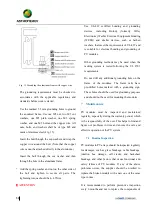
A certain distance between the PV module and the 

installation  surface  should  be  kept  to  prevent  the 

installation surface from touching the junction box. 


When  installing  on  the  roof,  comply  with  the  fire 

protection  requirements  of  the  building.  It  is 

recommended to install PV modules on a fireproof 

and  insulated  roof  covering,  and  ensure  adequate 

ventilation  between  the  PV  modules  and  the 

installation  surface.  In  order  to  ensure  the  fire 

rating  on  the  roof,  the  minimum  distance  between 

the frame of the PV module and the roof surface is 

10cm. 


The connector must be fully mated when wiring. If 

the  cable  is  too  long,  it  is  recommended  to  fix  the 

cable to the rack system with a UV-resistant nylon 

cable  tie.  When  fixing  the  cable  to  the  rack,  the 

bending radius of the cable should not be less than 

48mm. 


Avoid  directly  exposing  cables  and  connectors  to 

sunlight. Please use anti-UV cables. 

Summary of Contents for CHSM54M(BL)-HC

Page 1: ...1 Crystalline Silicon PV Module Installation Manual...

Page 2: ...1 Transport 6 4 2 Unpack 7 4 3 Stack 7 5 Mechanical installation 7 5 1 Environment 7 5 2 Tilt angle selection 8 5 3 Mounting Guide 8 5 3 1 Bolted mounting 9 5 3 2 Clamped mounting 10 6 Electrical Inst...

Page 3: ...ed with is beyond the control of Chint Solar Chint shall not be liable for any form of loss including but not limited to loss damage casualty or additional cost caused by improper installation operati...

Page 4: ...a or PV module storage area It is forbidden to install or use damaged PV modules It is forbidden to repair PV modules by unauthorized personnel including but not limited to replacing any part of PV mo...

Page 5: ...and be aware of bumps in the corners When installing or repairing the PV system do not wear any metal accessories to avoid the risk of electric shock if it is installed far above the ground please we...

Page 6: ...connector or make electrical connections in any other way 4 Handling and unpacking If the PV module is not in use please do not open the product packaging The goods should be stored in a dark dry and...

Page 7: ...from colliding and scratching with the cement surface hard object on the ground color steel tile metal corrugated etc When the PV modules are stacked they must be neatly and stably stacked on a horiz...

Page 8: ...tion The tilt angle of a PV module refers to the angle between the surface of the PV module and the ground surface as shown in Fig 1 The power output of a PV module is maximized when it faces the sun...

Page 9: ...raction effect therefore the space between two adjacent PV module frames should be no less than 10mm when mounted For detailed installation methods please refer to the following specifications 5 3 1 B...

Page 10: ...e installed across the support frame Fig 8 or parallel to the frame of the photovoltaic module Fig 9 When using clamps to install each module must be secured with a minimum of 4 clamps Fig 8 Rails ove...

Page 11: ...shown in Fig 10 and the fringe clamp shown in Fig 11 and Fig 12 The mid clamp has dimensions of a 40 mm b 26 mm c 5 mm d 28 mm 9 mm For module of 182mm wafer the size of mid and fringe clamp must mee...

Page 12: ...00Pa 2400Pa 5400 2400Pa Installation scope 198 408mm 2400 2400Pa Installation scope 50 200mm CHSM60M HC CHSM60P HC CHSM60M BL HC CHSM60M LV HC 1666 992 35 5400Pa 2400Pa 5400 2400Pa Installation scope...

Page 13: ...M HC CHSM54M BL HC CHSM54M LV HC 1708 1133 30 1708 1133 35 1722 1134 30 1722 1134 35 5400Pa 2400Pa 5400 2400Pa Installation scope 359 50mm 1400 1400Pa Installation scope 200 50mm CHSM6612M CHSM6612M H...

Page 14: ...m voltage for the regular module series is 1000V the 1500V standard products are also available according to the requirements The IEC UL standard maximum system voltage for half cell module series is...

Page 15: ...ge ratings conductor capacities fuse ratings and control sizes for PV output Depending on the maximum rated fuse current of the PV module and the local electrical installation standards the connection...

Page 16: ...ng connectors to direct sunlight and soaking in water Avoid the connectors falling on the ground or the roof Do not plug or unplug the connectors when the PV module is in live state When it is necessa...

Page 17: ...that meet the requirements of UL 467 and is suitable for electrical bonding and grounding of PV modules Other grounding methods may be used when the racking system is tested following the UL 2703 req...

Page 18: ...it is generally not necessary to clean the PV module as the rainfall will provide a self cleaning effect If there is a large accumulation of dirt on the PV module surface that has seriously affected t...

Page 19: ...released in June 2018 Rev 1 1 released in July 2020 Rev 1 2 released in October 2021 CHINT SOLAR ZHEJIANG Co Ltd Add 1335 Bin an Rd Binjiang District Hangzhou China 310053 Tel 86 571 5603 1888 Fax 86...

Reviews: